Project
AIM: - To study and prepare a technical report on a system-level simulation of an all-terrain vehicle, explaining the model properties and recording the outputs produced by the different case studies.
DESCRIPTION: -
ALL TERIAN VEHICLES:
An all-terrain vehicle (ATV) is defined as a motorized off-highway vehicle designed to travel on four low-pressure or non-pneumatic tires, having a seat designed to be straddled by the operator and handlebars for steering control.
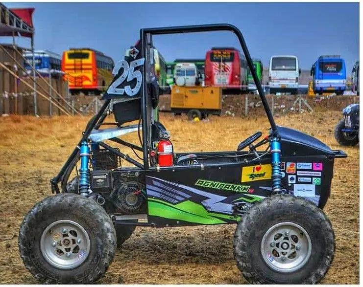
ATVs are subdivided into two types as designated by the manufacturer. Type I ATVs are intended by the manufacturer for use by a single operator and no passenger. Type II ATVs are intended by the manufacturer for use by an operator and a passenger and are equipped with a designated seating position behind the operator. Similarly, riders must also consider the various ATV sizes.
ATVs are not “one size fits all.” The ATV industry recommends all riders operate an ATV intended for their age. Youth model ATVs are designed for smaller hands and feet and travel at slower speeds appropriate for their age.
CASE:1
OPEN-LOOP
STUDY:1
Simscape Model of Continuously Variable Transmission (CVT) BAJA All-Terrain Vehicle (ATV)
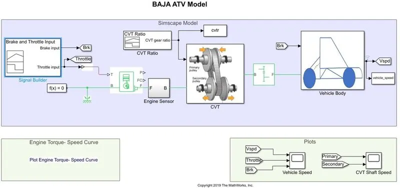
Key Components of the Model:
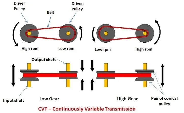
CVT: - A continuously variable transmission (CVT) is an automatic transmission that can change seamlessly through a continuous range of gear ratios. This contrasts with other transmissions that provide a limited number of gear ratios in fixed steps. The flexibility of a CVT with suitable control may allow the engine to operate at a constant RPM while the vehicle moves at varying speeds.
CVT systems work through a pulley system. In short, this system consists of cones at each pulley connected via a chain belt. The cones can move to increase or decrease the belt diameter to change gear ratios, allow for quick shifting into the needed ratio for increased power, and boost fuel economy.
One pulley in the CVT is connected to the engine and the other directs power to the wheels. The width of these pulleys changes based on the needed power; as one gets larger, the other gets smaller. This allows a CVT to deliver strong and seamless acceleration.
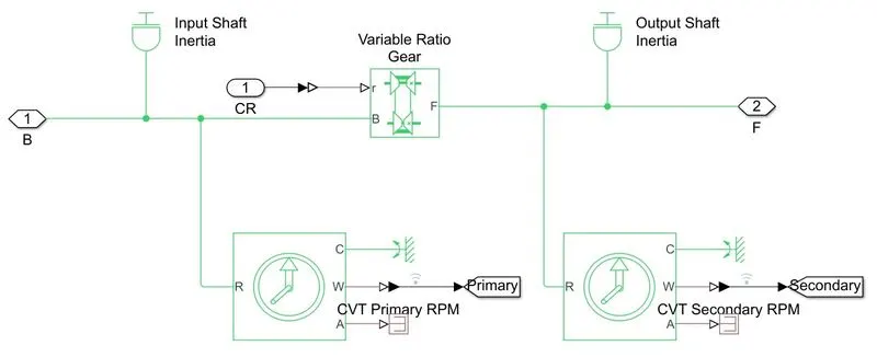
As shown in the below image of the CVT model here Inertia blocks were connected to the variable ratio transmission which will provide the function of the pulley.
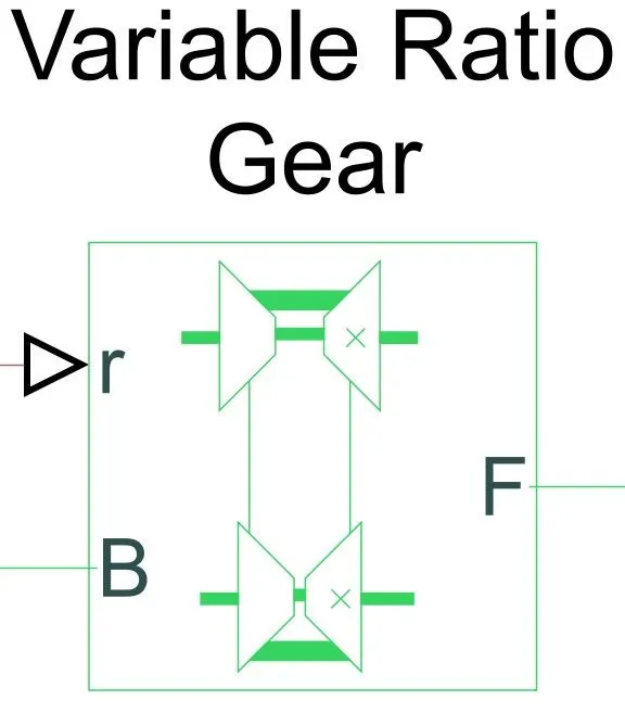
Variable Ratio Transmission: -
The Variable Ratio Transmission block represents a gearbox that dynamically transfers motion and torque between the two connected driveshaft axes, base, and follower.
Ignoring the dynamics of transmission compliance, the driveshafts are constrained to corotate with a variable gear ratio that you control. You can choose whether the follower axis rotates in the same or opposite direction as the base axis. If they rotate in the same direction.
Engine: -
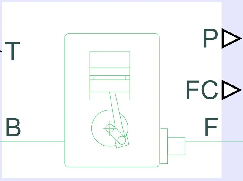
The Generic Engine block represents a general internal combustion engine. Engine types include spark-ignition and diesel. Speed-power and speed-torque parameterizations are provided. A throttle physical signal input specifies the normalized engine torque. Optional dynamic parameters include crankshaft inertia and response time lag. A physical signal port outputs engine fuel consumption rate based on the choice of fuel consumption model. Optional speed and redline controllers prevent the engine to stall and enable cruise control.
Vehicle Body: -
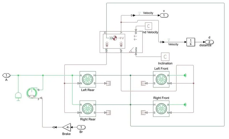
The Vehicle Body block represents a two-axle vehicle body in longitudinal motion. The vehicle can have the same or a different number of wheels on each axle. For example, two wheels on the front axle and one wheel on the rear axle. The vehicle wheels are assumed identical in size. The vehicle can also have a center of gravity (CG) that is at or below the plane of travel.
The block accounts for body mass, aerodynamic drag, road incline, and weight distribution between axles due to acceleration and road profile. Optionally include pitch and suspension dynamics. The vehicle does not move vertically relative to the ground.
The block has an option to include an externally-defined mass and externally-defined inertia. The mass, inertia, and center of gravity of the vehicle body can vary over the course of simulation in response to system changes.
Input Signal: -
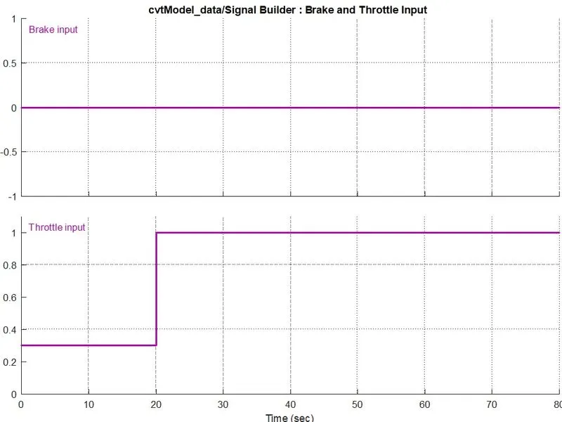
The input signal to the Engine is given as Brake input is ‘0’ and the throttle input is ‘0.3 to 1’.
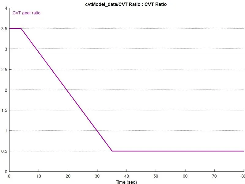
CVT Gear ratio: -
A continuously variable transmission (CVT) is a particular automatic transmission capable of providing a smoothly varying gear ratio. Unlike a conventional automatic gearbox, the CVT has no fixed gears. It varies the drive ratio continuously by changing the operating diameters of two pulleys that are linked by a steel V-belt. Actually, no gears are involved! Instead, we call it speed ratio, which is the same as the gear ratio for the geared transmission systems. (Though we can also use speed ratio in case of geared transmission systems as well)
Simple Gear: -
The Simple Gear block represents a gearbox that constrains the connected driveline axes of the base gear, B, and the follower gear, F, to corotate with a fixed ratio that you specify. You choose whether the follower axis rotates in the same or opposite direction as the base axis. If they rotate in the same direction, the angular velocity of the follower, ωF, and the angular velocity of the base, ωB, have the same sign. If they rotate in opposite directions, ωF and ωB have opposite signs.
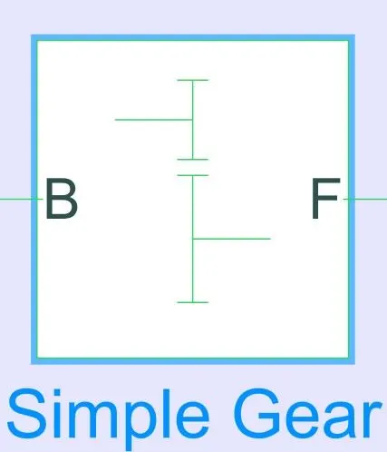
To connect the engine and the CVT, to need some speed reduction we have used a simple gear ratio. It is a mechanical system like some gear it seems to need to set a certain ratio. Here the ratio is given as 12.
Engine Torque-Speed Curve: -
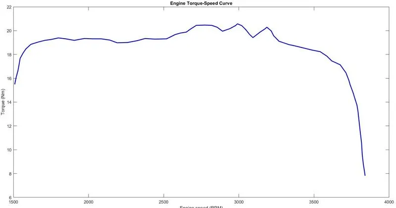
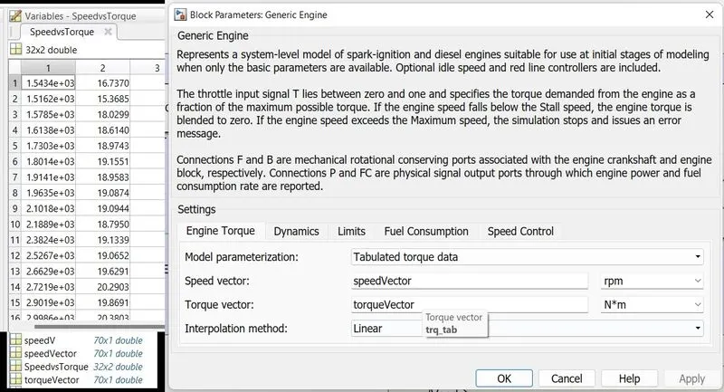
The plot is the torque-speed curve of the BAJA(ATV) engine. Here used the same data to feed the engine. By using the MATLAB extension Grabit we take the data points from the plot and then feed them into the engine block.
The output of Simscape Model of Continuously Variable Transmission (CVT) BAJA All-Terrain Vehicle (ATV)
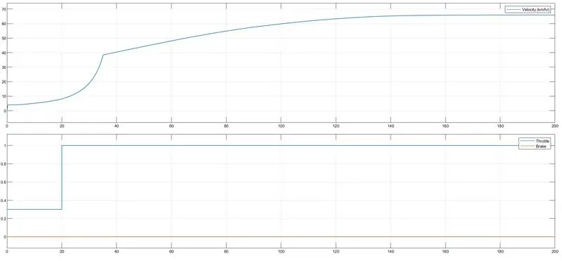
From the obtained output we can see that ATV achieved its maximum speed of 55km/hr at full throttle after t= 30sec and remains constant. There is no effect on velocity reduction due to the given brake signal being ‘0’.
The output of the CVT shaft
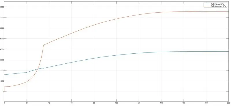
These plots show the variation in angular velocity of primary and secondary shafts of the variable gear transmission system. These values differ with respect to the gear ratio.
STUDY:2
Simscape Model of Continuously Variable Transmission (CVT) BAJA All-Terrain Vehicle (ATV) using Dashboard
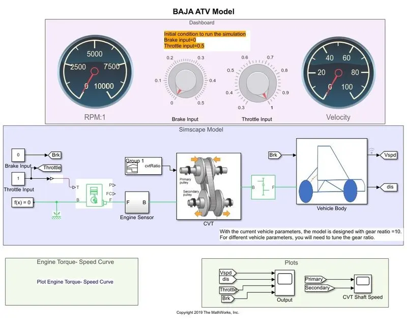
In this model, providing the input signal Throttle and brake input from a dashboard instead of a signal builder. The remaining blocks were the same as in the study above. (Case-1 Study-1)
The motive of using a dashboard is to study the output value with the variation in the input values of throttle and brake, it will give the value of RPM and Velocity of the engine in the digital reading.
The output of Simscape Model of Continuously Variable Transmission (CVT) BAJA All-Terrain Vehicle (ATV) using Dashboard
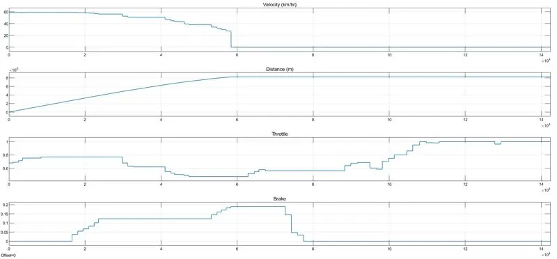
From the above plot, we can see that the velocity increases suddenly from 0 to 60kmph when the throttle input is 0.6 and brake input is 0. When the brake input applied value increased from 0 to 0.2 the velocity of the vehicle decreased to 0. So that we see the direct effect of throttle and brake input.
The output of the CVT shaft
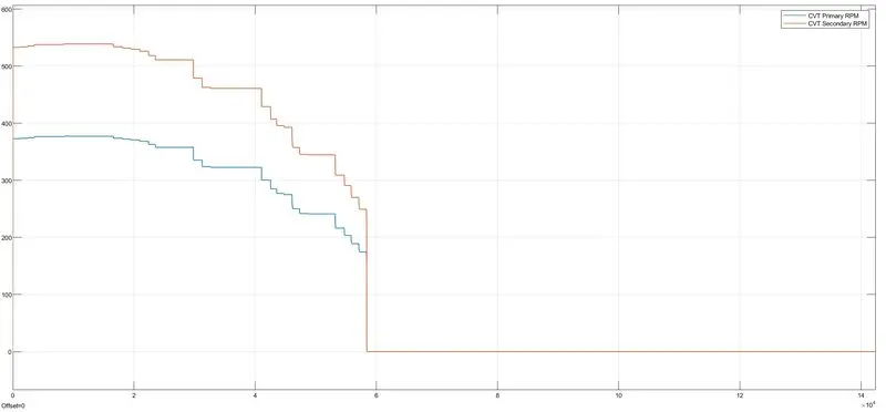
With the sudden rise in vehicle velocity, the angular velocity of the primary and secondary shaft also increased, when the brake input was applied both shaft velocities decreased to 0 and remain constant.
CASE:2
CLOSED-LOOP
STUDY:1
Simscape Model of Continuously Variable Transmission (CVT) BAJA All-Terrain Vehicle (ATV) Using Look-Up Table
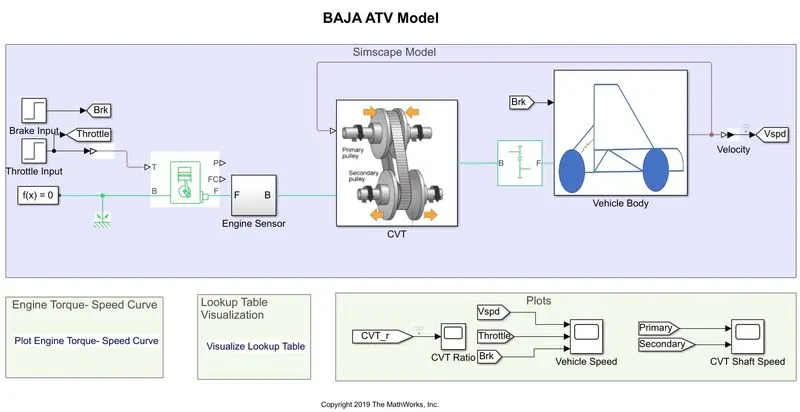
CVT Block
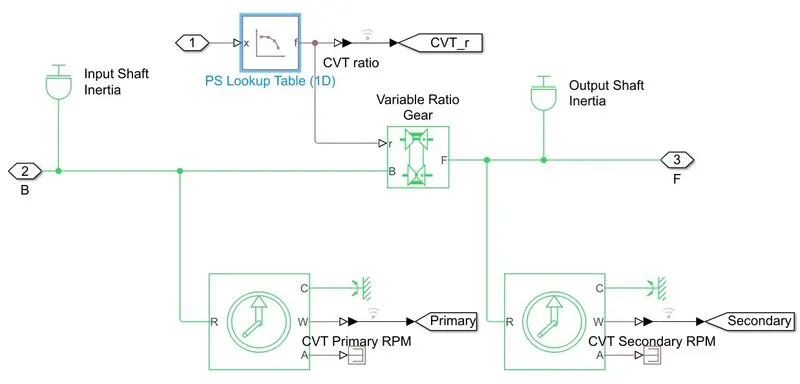
The main difference between this model and the Case-1 study-1 model is that the gear ratio input to the CVT ids is provided by the Look-Up table. The remaining blocks and parameters were kept the same as before.
Look up Table Visualization
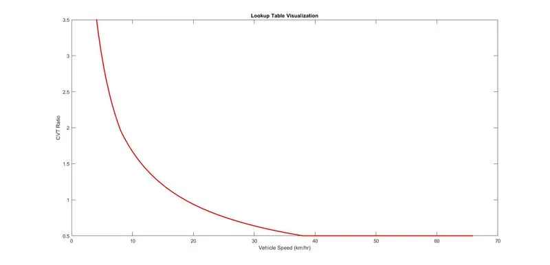
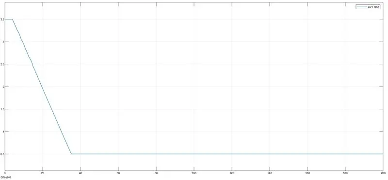
The output of Simscape Model of Continuously Variable Transmission (CVT) BAJA All-Terrain Vehicle (ATV) Using Look-Up Table.
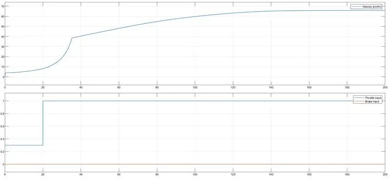
The output of the CVT shaft
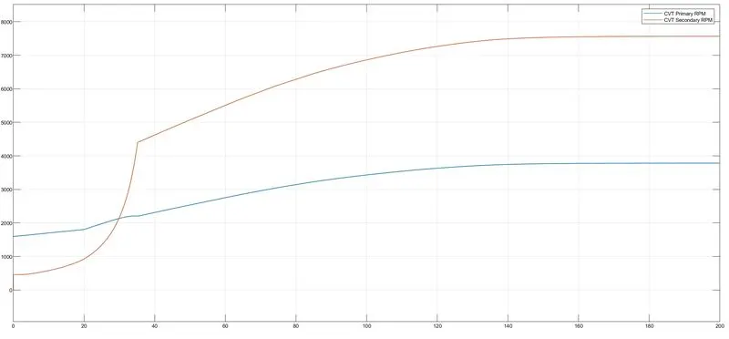
From the above outputs, we can see that they were similar to the Case-1 study-1 model since the inputs were the same.
STUDY:2
Simscape Model of Continuously Variable Transmission (CVT) BAJA All-Terrain Vehicle (ATV) Using Dashboard and Look-Up Table
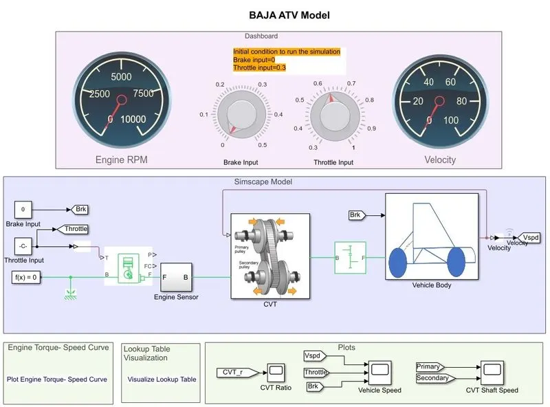
In this model, a dashboard is used to control the inputs: Throttle & Brake with the knobs.
The output of Simscape Model of Continuously Variable Transmission (CVT) BAJA All-Terrain Vehicle (ATV) Using Dashboard and Look-Up Table.
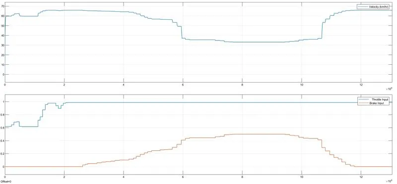
We can see a similar output in Case-2 Study-2, the velocity increases suddenly from 0 to 60kmph when the throttle input is 0.6 and brake input is 0. When the brake input applied value increased from 0 to 0.5 the velocity of the vehicle decreased accordingly since throttle input was kept as 1.
The output of the CVT shaft
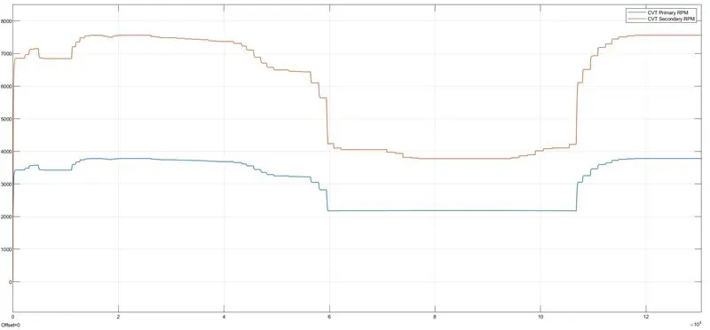
We can see the variation in RPM of primary and secondary shafts with respect to input parameters.
CONCLUSION:
System-level simulation of Continuously Variable Transmission (CVT) BAJA All-Terrain Vehicle (ATV) with and without dashboard and Look-up Table has been carried out with respect to variations in input throttle and brake and a detailed study report of the model has been prepared.