Project 1
Project:
Simulate the starting behaviour of a 5 horsepower(3.75kW), 3-phase 3-wire, 230V, 60Hz, 4-pole squirrel cage induction machine with parameters: -
- rs=0.531Ω,
- Lls=Llr=2.52mH
- rf=0.408Ω
- Lm=84.7mH
- J=0.1kgm2
The machine is suddenly connected to a balanced three-phase 230Vrms sinusoidal supply voltage at a frequency 60Hz. After reaching the rated speed the motor is loaded to 0.83 times the rated torque at 0.7secs. The load is removed after 0.1 sec.
Aim: -
Develop a dynamic model of squirrel cage induction motor and test with variable load torque condition in MATLAB-Simulink Environment and provide the start-up behavior characteristics of Induction motor concerning to d-q reference frame, Synchronous reference frame, rotor reference frame, and rotor flux reference frame.
Squirrel Cage Induction Motor
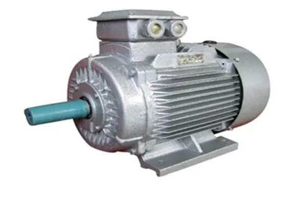
A Squirrel cage motor is one type of induction motor. To generate motion, it hardens electromagnetism. As the output shaft is connected to the rotor inner component which is looking like a cage. Hence it is called a squirrel cage. The two-end caps i.e., circular in shape are joined by rotor bars. These are acted based on the EMF i.e., generated by the stator. This EMF is also generated outer housing that is made of laminated metal sheets and wire coiling. The squirrel cage is a simple method of pulling an electromagnetic induction effect. A 4-pole squirrel cage induction motor is shown above.
Squirrel induction motor working is based on the principle of electromagnetism. When the stator winding is supplied with a three-phase AC, it produces a rotating magnetic field (RMF) which has a speed called synchronous speed. This RMF causes voltage induced in the rotor bars. So, that short-circuit current flows through that. Due to these rotor currents, a self-magnetic field is generated which interacts with the stator field. Now, as per the Lenz law, the rotor field starts opposing its cause. when the RMF catches the rotor moment, the rotor current drops to zero. Then there would be no relative moment between the rotor and RMF.
Hence, the zero tangential force is experienced by the rotor and reduces for a moment. After this reduction in the moment of the rotor, the rotor current is induced again by the reconstruction of relative motion between the RMF and the rotor. Hence the tangential force of the rotor for the rotation is restored and starts by following the RMF. In this case, the rotor maintains a constant speed, which is less than the speed of RMF and synchronous speed. Here, the difference between the speed of RMF and the rotor is measured in the form of a slip. The final frequency of the rotor can be obtained by the multiplication of slip and supply frequency.
Dynamic Analysis of Induction Motor
To derive the mathematical model of a 3-phase Induction motor, the theory of reference frames has been effectively used as an efficient approach. Dynamic models (mathematical models) are employed to better understand the behavior of induction motors in both transient and steady states. The dynamic modeling sets all the mechanical equations for inertia, torque, and speed versus time. It also models all the differential voltage, currents, and flux linkages between the stationary stator as well as the moving rotor.
dq-axis Equivalent Circuit Model of IM:
A step-by-step MATLAB/Simulink implementation of an induction machine using dq0 axis transformations of the stator and rotor variables in the arbitrary reference frame. Thus, every single equation among the model equations can be easily implemented in one block so that all the machine variables can be made available for control and verification purposes.
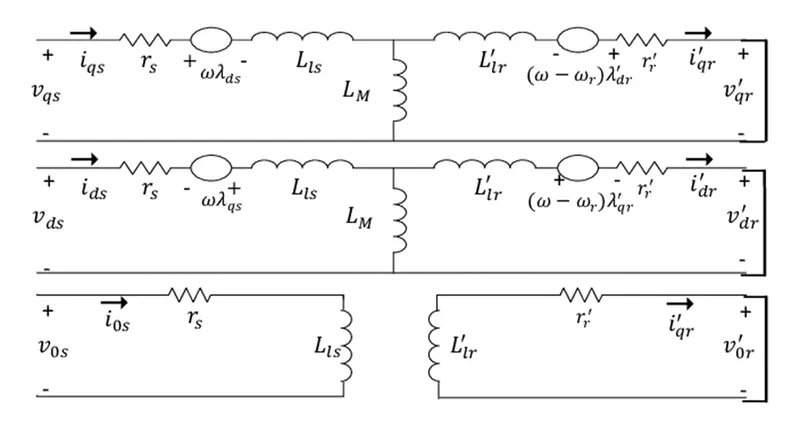
Fig: - The dq0 equivalent circuit of an induction motor
Conversion of 3-ph voltages to dq-Axis voltage:
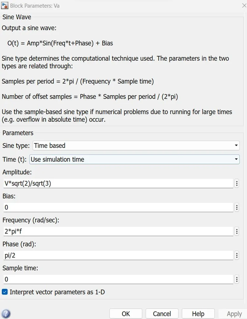
The three-phase stator voltages of an induction machine under balanced conditions are expressed as
Va=√2Vrms sin(ωt)
Vb=√2 Vrms sin(ωt−2π3)
Vc=√2 Vrms sin(ωt+2π3)
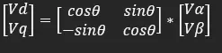
These three-phase voltages are transferred to a synchronously rotating reference frame in only two phases (d-q axis transformation). This can be done using the following two equations.
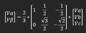
Then, the direct and quadrature axes’ voltages are
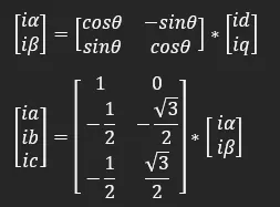
The instantaneous values of the stator and rotor currents in three-phase system are ultimately calculated using the following transformation:
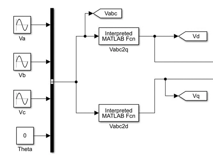
Conversion of Vabc to Vd & Vq in MATLAB:
Vd = 2/3*((u(1)*cos(u(4)))+(u(2)*cos(u(4)-(2*pi/3)))+(u(3)*cos(u(4)+(2*pi/3))))
Vq= 2/3*((u(1)*sin(u(4)))+(u(2)*sin(u(4)-(2*pi/3)))+(u(3)*sin(u(4)+(2*pi/3))))
Equations of Flux Linkages
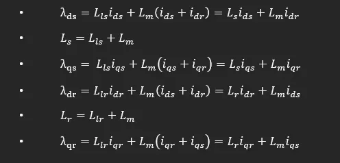
The dynamic model of induction motor in arbitrary reference frame can be represented by using flux linkages as variables. This involves the reduction of a number of variables in dynamic equations. Even when the voltages and currents are discontinuous, the flux linkages are continuous. This gives the advantage of differentiating these variables with numerical stability. In addition, the flux linkages representation is used in motor drives to highlight the process of the decoupling of the flux and torque channels in the induction and synchronous machine. The various flux linkage equations are expressed as:
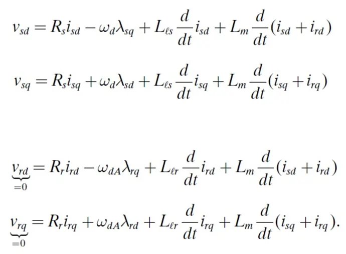
Where,
- Rs: stator resistance
- Rr: rotor resistance
- Wd: Initial speed of the rotor
- WdA: Wd- Wr
- Wr: Rotor reference speed developed by the load torque.
- Lls: stator self-inductance
- Llr: rotor self-inductance
- Lm: Mutual Inductance
- λsd, λsq: Stator flux linkages
- λrd, λrq: Rotor flux linkages
- isd, isq: Stator currents
- ird, irq: Rotor currents
- Vsd, Vsq: Stator Voltages
- Vrd, Vrq: Rotor Voltages
The flux linkage expressions of the stator and rotor in the dq axes, it is found that the main purpose of the transformation has been achieved. In other words, by employing the reference frame transformation, the time-varying mutual inductances due to the relative motion between the stator and rotor windings become constant in the dq reference frame. This result can be valid regardless of the rotating speed of the reference frame. Furthermore, the flux linkages become magnetically decoupled between the d- and q-axes. Flux linkages of an induction motor in the dq axes are:
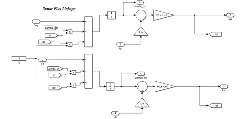
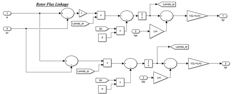
Modeling of Stator and Rotor flux linkage with the help of above governed equations
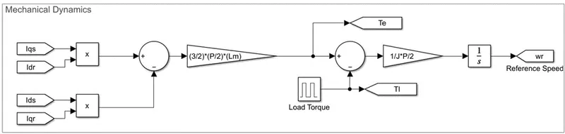
The Electromagnetic torque and rotor speed can be determined as follows,
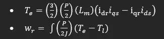
With P = no of poles of Machine.
Te= Electromagnetic torque developed
Modeling of Mechanical dynamics by using above governed equations
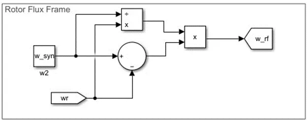
Modeling of reference frame
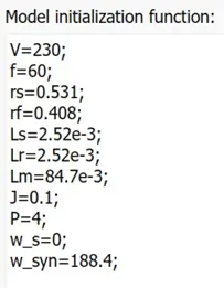
- w_syn =120f/P =120*60/4 = 1800RPM
- Conv RPM to rad/sec : RPM*((2*pi)/60)
- w_syn (rps) = 1800*((2*pi)/60) = 188.4 rps
The motor speed developed by the Mechanical Dynamics is consider as the speed for Rotor Reference frame.
For Rotor flux reference frame:
Rotor flux speed = slip*motor speed = [(w_syn – wr)/w_syn]*wr
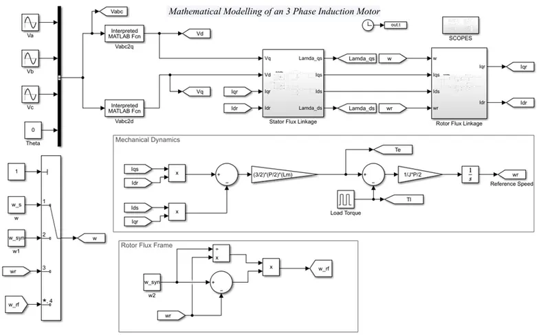
Simulink Model of Induction motor with required reference frame input, along with given parameters:
a) Simulate the start-up behaviour of the induction motor represented in the stationary d-q reference frame.
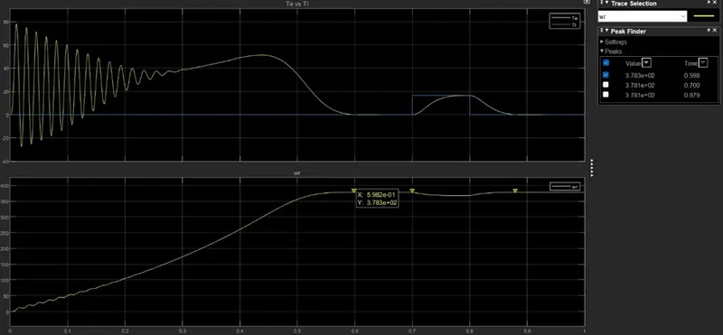
In stationary d-q ref frame with initial rotor speed w=0 rad/sec, the motor speed reaches its max speed of 378.3 rad/sec when the electromagnetic torque matched with load torque, when the load torque(Tl) =0 Nm, the developed electromagnetic torque(Te) becomes 0, the motor achieved it max speed.
After applying the Tl, the Te gets affected as well as the motor speed and Te tries to match with Tl, when it gets coincide again it motor reaches it max speed and sustain once load torque got released.
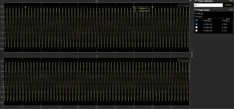
In stationary d-q ref frame, Vds and Vqs = 188V are having constant frequency of 120 Hz.
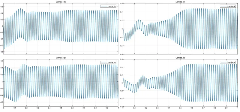
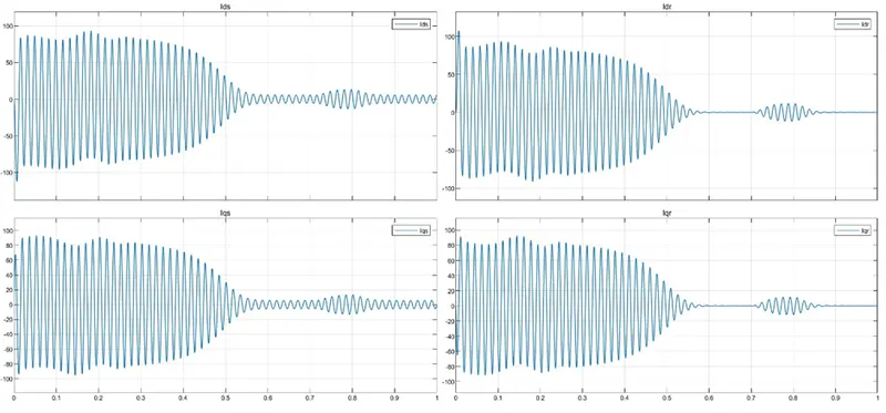
In stationary d-q ref frame, Idr and Iqr are dependent on load. If there is no load the value is 0. Ids and Iqs have the frequency of 120 Hz.
b) Simulate the start-up behaviour of the induction motor represented in the synchronous reference frame.
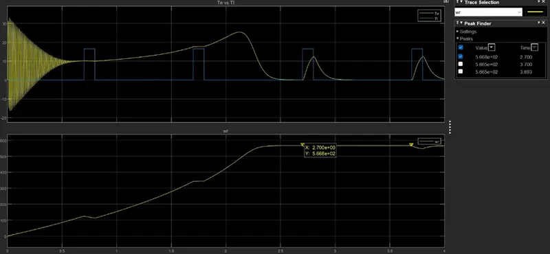
In synchronous reference frame with initial rotor speed w= 188.4 rad/sec, When the load torque applied the electromagnetic is not get effected at initial instant though motor speed gets effected, but it tries to match the load torque, when the Te gets matched with Tl the motor speed reaches its max speed of 566.8 rad/sec. Once the motor reaches its max speed, the effect of load torque makes little disturbance and will reach max speed once the load torque is disconnected.
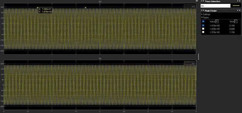
In stationary d-q ref frame, Vds and Vqs = 188V are having constant frequency of 180 Hz.
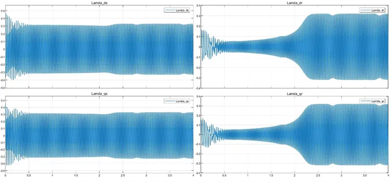
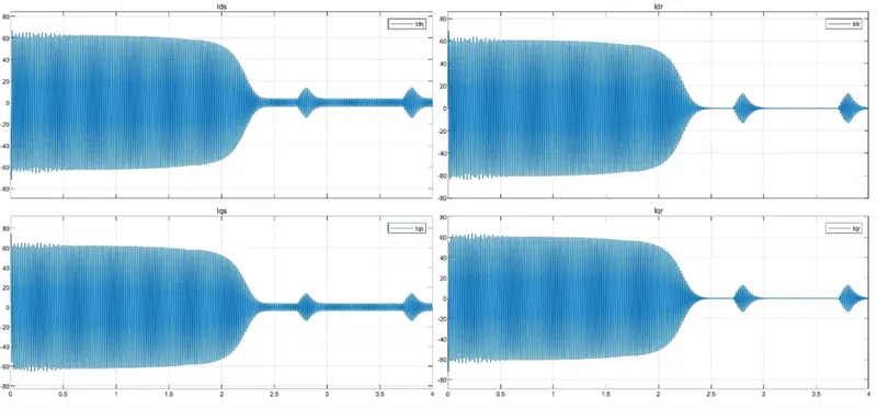
In synchronous reference frame, Idr and Iqr are dependent on load. If there is no load the value is 0. Ids and Iqs have the frequency of 180 Hz.
c) Simulate the start-up behaviour of the induction motor represented in the rotor reference frame.
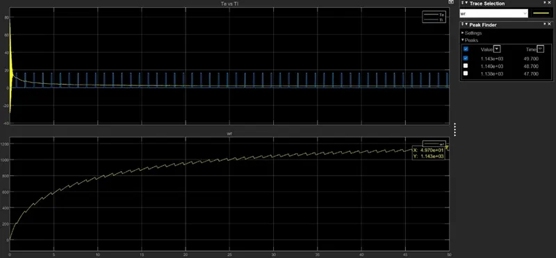
The rotor reference frame is that motor speed is the reference speed, so that the motor electromagnetic torque won’t able to match the load torque, and never gets ‘0’. The motor will experience the high speed of 1143 rad/sec with high supply frequency.
The effect of load torque will experience by the motor speed, but the electromagnetic torque will get settled at constant value.
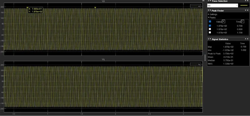
In rotor ref frame, Vds and Vqs = 188V are having constant frequency of 360 Hz.
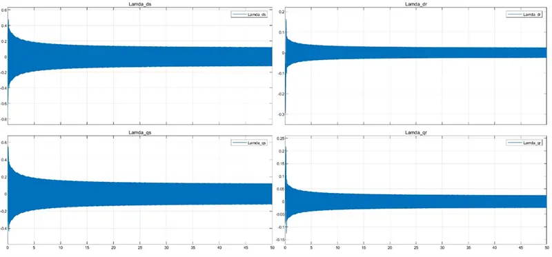
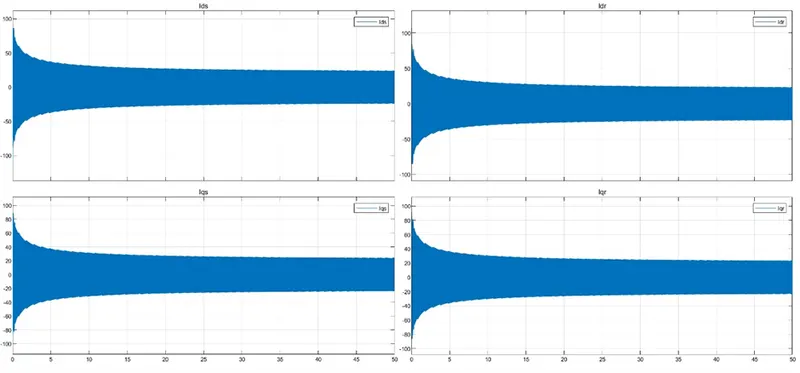
As we seen that the electromagnetic didn’t get the effected by the load torque and it get settled by a non-zero value similarly the stator and rotor currents also won’t experience the effect of load torque.
d) Simulate the start-up behaviour of the induction motor represented in the rotor flux reference frame.
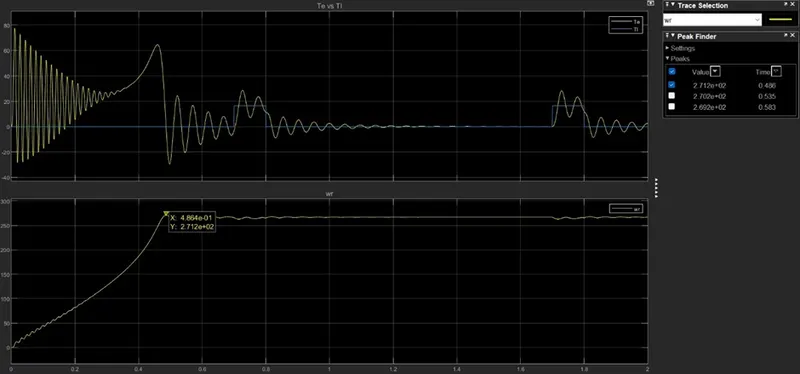
The rotor flux reference frame means the speed reference of the motor is slip speed of the induction motor. At the instant the generate electromagnetic torque matched the no load torque the motor achieved its max speed of 271.2 rad/sec. When the load torque applied experienced the disturbance in electromagnetic torque and it gets settled gradually once the load torque removed. Since Te tries to match the Tl more than one time when the load torque is applied, motor speed also experienced the disturbance but not as much as Te.
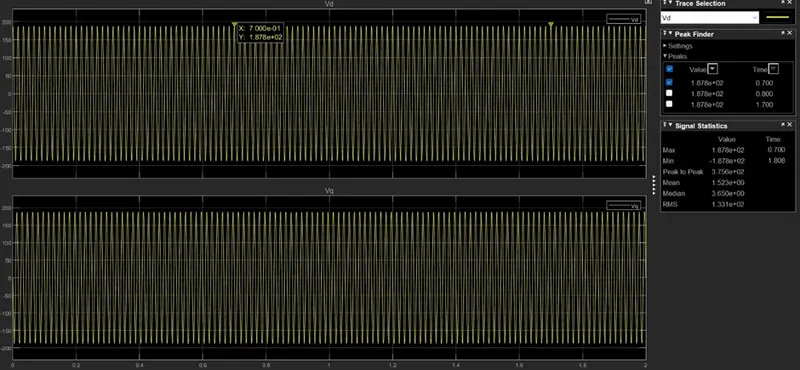
In rotor flux ref frame, Vds and Vqs = 188V are having constant frequency of 90 Hz.
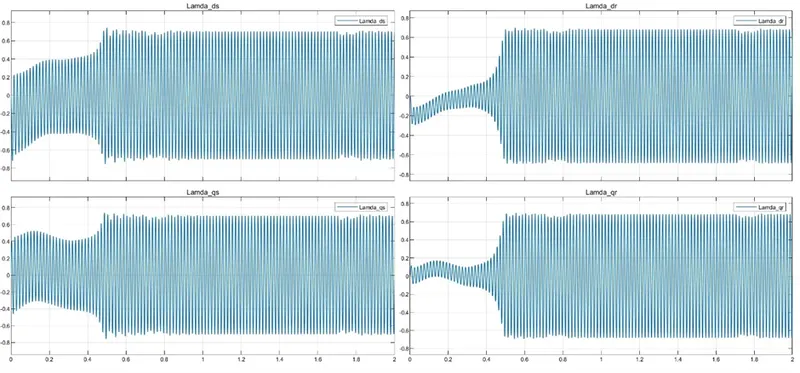
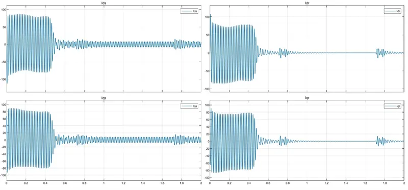
Since the electromagnetic torque is experience the disturbance similarly rotor current also experience the effect of load torque and gets settled once it removed.
CONCLUSION:
The given specifications are applied to the mathematical model of the induction motor by using the Simulink and different reference frames are applied so that the flux linkages, currents, and torque as well as the rotor speed characteristics are observed.
Observed that, each reference frame the behaviour of motor is producing different max speed, and accordingly frequency variation of the Vd, Vq, Id, Iq, λ_d, λ_q.