Project 2 - Modeling of 3 phase Induction Motor Drive
EV Refresher
Project-2
Q3.
Model 3 phase induction motor with a 3 phase inverter using Direct Torque control using an Average Model, Implement both torque and flux control to achieve the desired power.
Design Parameters:
- Initial Speed = 0 RPM
- Flux Target = 2.5 webers
- DC Voltage = 500 V;
- Fundamental Frequency = 60 Hz
- Speed Step Time = 0.01 secs
- Determine fundamental speed based on fundamental frequency
- Determine the switching sequence for direct torque control
- Moment of Inertia = 0.1 Kgm^2
- Load Torque Initial = 0 Nm
- Final Load Torque = 50 Nm
- Torque Step Time = 0.03 secs
Motor Parameters: (Create an Average Model)
- Stator Resistance = 0.5 Ohms
- Rotor Resistance = 0.2 Ohms
- Stator Leakage Inductance = 20 mH
- Rotor Leakage Inductance = 10 mH
- Magnetizing Inductance = 200 mH
- Number of Poles = 4
- Torque to Speed
SOL: -
AIM: -
The control of the Induction motor by tracking the reference of magnetic flux and electromagnetic torque, by means of the application of suitable values of stator voltage of the machine.
Definition:
The Direct Torque control electric drive with IM supplied by a voltage source inverter (VSI), it is possible to directly control the stator (or rotor or even magnetizing) flux linkage and the electromagnetic torque by the selection of optimal switching configurations of the Inverter.
The Selection of such switching configurations is made to maintain instantaneously the loci of stator flux linkage and electromagnetic torque inside hysteresis bands centered on the relative reference values.
This kind of control results in high dynamic performance in torque response, the low switching frequency of the inverter, and low losses due to the harmonics.
Block Diagram of Direct Torque Control of an Induction Motor Drive
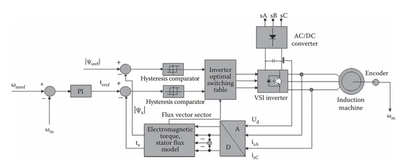
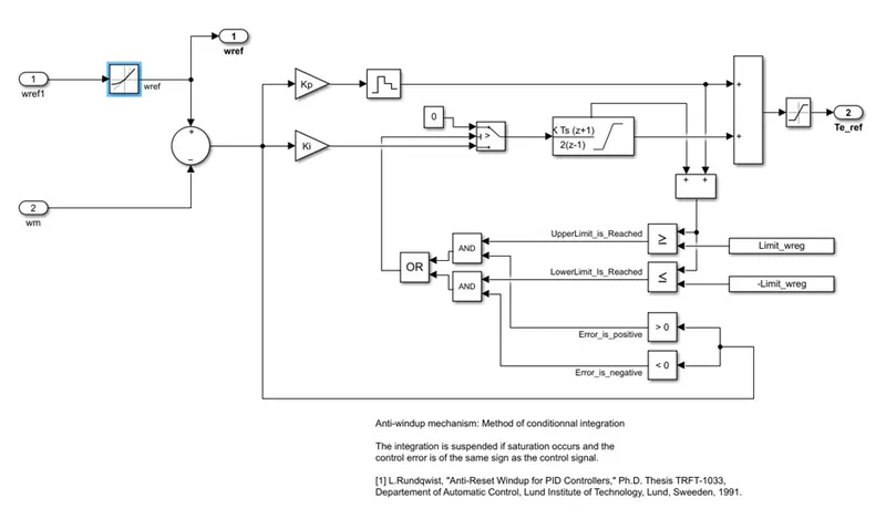
The closed-loop control of the IM speed wm and the stator flux Psi_s is performed. The machine’s measured speed wm is compared with its reference wm_ref, and the tracking error is processed by the PI controller. The output of the speed controller is the torque reference t_ref.
The t_ref which is compared with estimated torque te, computed by the flux and the torque model, is the tracking error processed by a hysteresis comparator, whose output is one of the inputs of the block “Inverter optimal switching table”.
The flux and the torque model performing Clarke’s transformation, here the phase voltage has been reconstructed by the knowledge of the DC link voltage Ud and the switching patterns of the the Inverter Sa, Sb, and Sc.
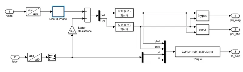
The stator flux reference Psi_sref is compared with the estimated one Psi_s, computed as shown in the above figure, and the tracking of the error is processed by a hysteresis comparator, whose output is the other input of the block “Inverter optimal switching table”.
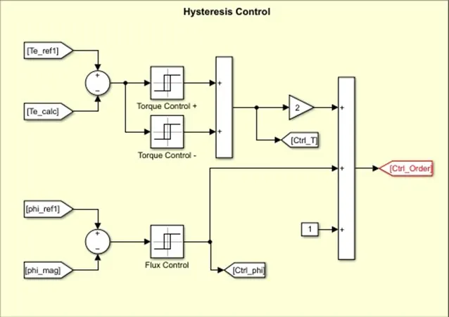
The block “Inverter optimal switching table” chooses, at each sampling time of the control system, the optimal configuration of the inverter on the basis of the angular position of the stator flux linkage space- vector.
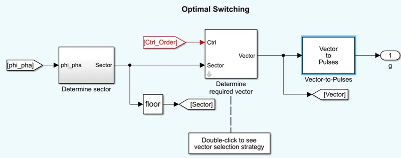
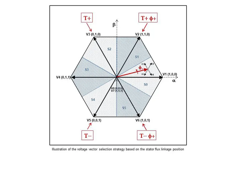
Simulink model of DTC of IM
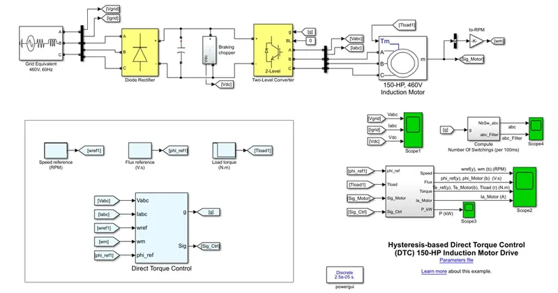
Model Parameters: Parameters were changed as given
%% Parameters file for SPS model: power_motordrive_IM_DTC_HYST.slx
Ts_Power=25e-6; % SPS sample time (s)
%% Induction motor parameters
Pn = 111.9e3; % Nominal power (W)
Vn = 460; % Nominal rms phase-to-phase voltage (V)
fn = 60; % Nominal frequency (Hz)
%
Rs = 0.5; % Stator resistance (Ohm)
Lls = 20e-3; % Stator leakage inductance (H)
Rr = 0.2; % Rotor resistance, referred to the stator side (Ohm)
Llr = 10e-3; % Rotor leakage inductance, referred to the stator side (H)
Lm = 200e-3; % Mutual inductance (H)
%
J = 0.1; % Inertia (kg.m^2)
Friction = 0.02154; % Friction factor (N.m.s)
p = 2; % Number of pole pairs
Tn= Pn/(2*pi*fn/p); % Nominal torque (N.m);
phi_n=(Vn/sqrt(3)*sqrt(2)/(2*pi*fn)); % Nominal flux (V.s)
%% Control parameters
Ts_Control=25e-6; % Control sample time (s)
%
% Speed regulator
wref_RateOfChange=1200; % Maximum rate of change for speed reference (RPM/s)
Kp_wreg=100; % Proportional gain
Ki_wreg=1000; % Integral gain
Limit_wreg=1.5*Tn; % Regulator output(torque) limit
T_hyst_band=10; % Torque hysteresis band (% of nominal torque)
phi_hyst_band=2.5; % Flux hysteresis band (% of nominal flux)
%% DC link
Clink = 25e-3; % DC link capacitor (F)
% Braking chopper
Rbrake=8; % Resistance (ohm)
Switch_on_point=710; % Switch on point (V)
Switch_off_point=665; % Switch off point (V)
%% End of file
Results:
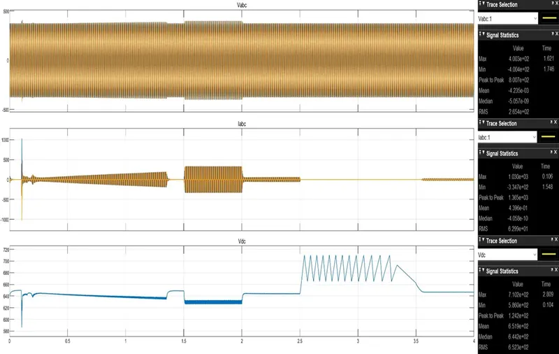
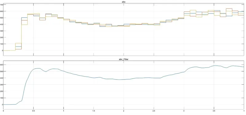
Vabc, Iabc, Vdc:
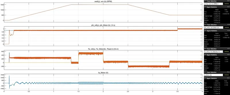
Speed, Flux, Torque, Motor Current Estimated
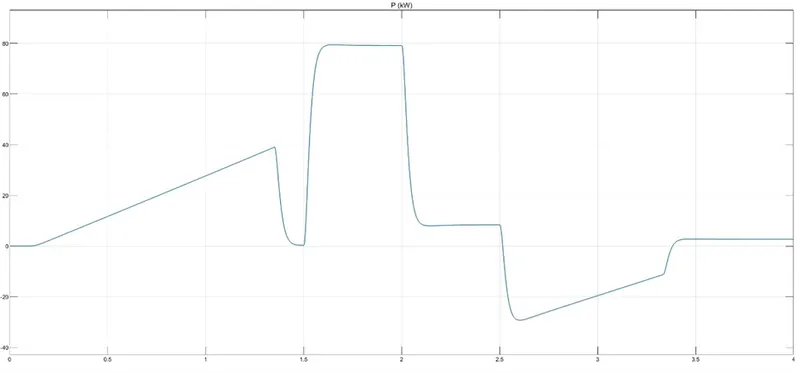
Power Consumption of IM
Number of Switching’s:
Q2. Use the 3-phase inductor motor theory to derive the transfer function of 3 phase Induction Motor
SOL: -
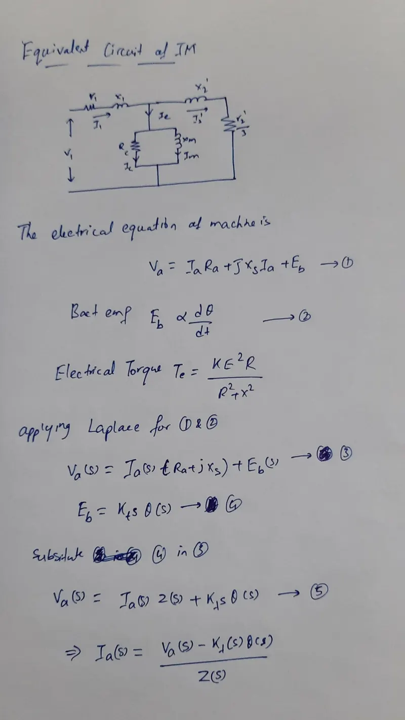
Equivalent circuit of IM:
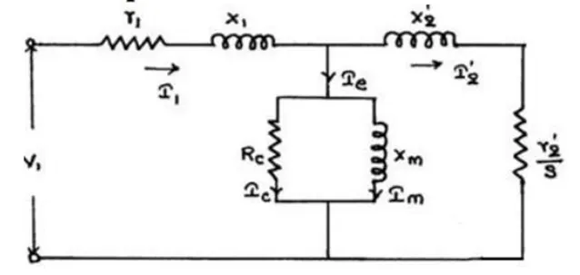
- r1 = resistance of Stator
- X1 = Stator leakage reactance
- I1 = Stator current
- Rc = Shunt branch resistance
- Xm = Magnetizing reactance
- Ie = Per-phase no-load current
- I2 = Rotor current
- I2 ’ = Rotor Current per phase referred to stator
- X2 ’ =Standstill rotor reactance referred to stator
- r2 ’ = rotor resistance referred to stator
- V1 = Stator voltage
- E1 = Stator induced emf
- s = slip
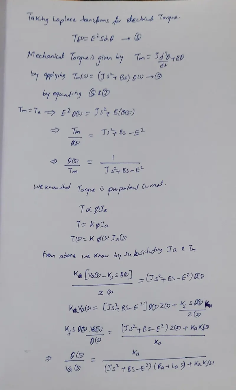
Transfer function of Induction Motor: