Week 9 Challenge
AIM: -
Modeling the energy management strategy that distribution of propulsion power or positive power load sharing happened between Battery, Fuel Cell, and Ultracapacitor. Accordingly plotting the outputs power request from UC, fuel cell, and battery.
Description: -
Energy management strategy (EMS) is an important link during the HEV/PHEV design procedure, which can govern the energy flow between the fuel tank and the electric energy storage by solving the energy distribution problem as well as maintaining the state of charge of the energy sources. With the continuous development of intelligent connected vehicle technology, designing an efficient EMS with vehicle-to-infrastructure/vehicle-to-vehicle.
Considering that to model a system the total power demand is in the range of (0 to 90) kW. The energy system strategy of the system is following as shown below.
|
Power Demand |
Conditions |
Energy Source |
|
0-9999 |
If UC_SOC >35% |
UC |
|
If UC_SOC <35% |
Fuel Cell |
|
|
10000-22999 |
If SOC_Batt >35% |
Battery |
|
If SOC_Batt<35% |
Fuel Cell |
|
|
23000-54999 |
No Condition |
Fuel Cell |
|
55000 -90000 |
If UC_SOC >35% |
UC |
|
If UC_SOC<35% |
FC |
Flow Chart for the positive power distribution
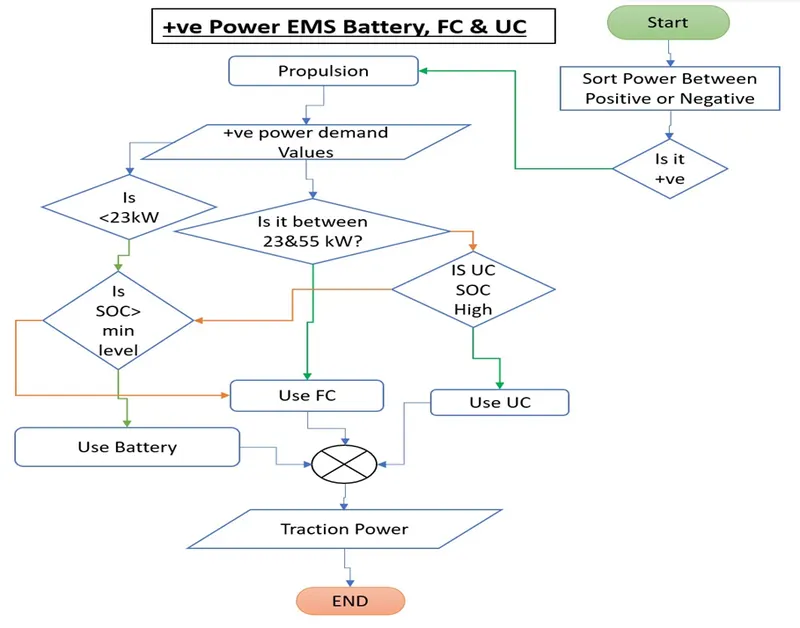
The power demand to the system is to be defined as either positive power (Propulsion) or negative power (Regeneration).
The power input given to the system is shown below.
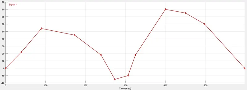
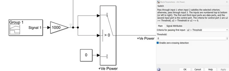
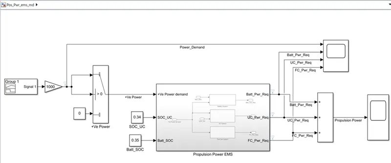
From the above to separate the propulsion power a switch block is used by applying the condition that the input should be > 0.
Modeling of the energy source load-sharing model as per the considered conditions.
Battery System: -
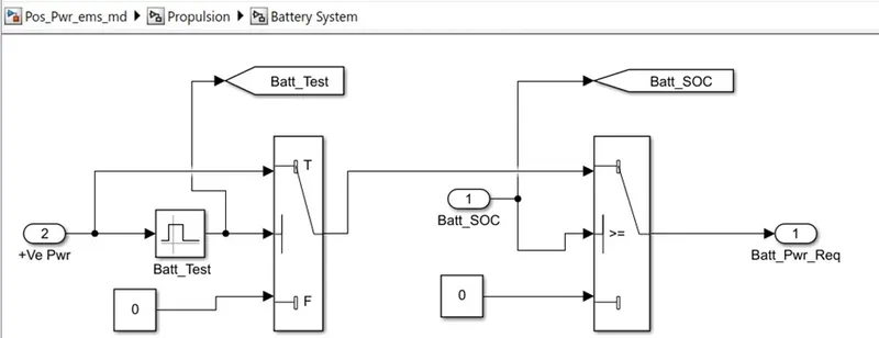
In the Battery system, if the power demand is between 10000 to 22999 watts and the battery SOC is > 35% then the power supply will be provided from the Battery system.
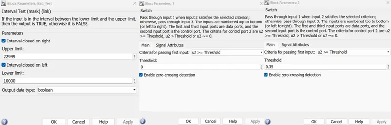
If the power demand in the limit of the system and the SOC is <35% then the power supply will be provided Fuel cell system as the backup to the Battery system.
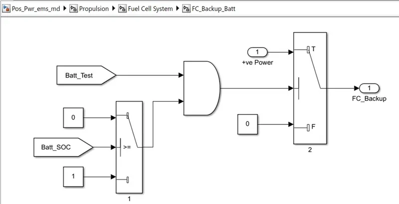
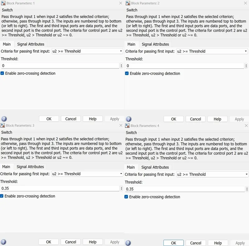
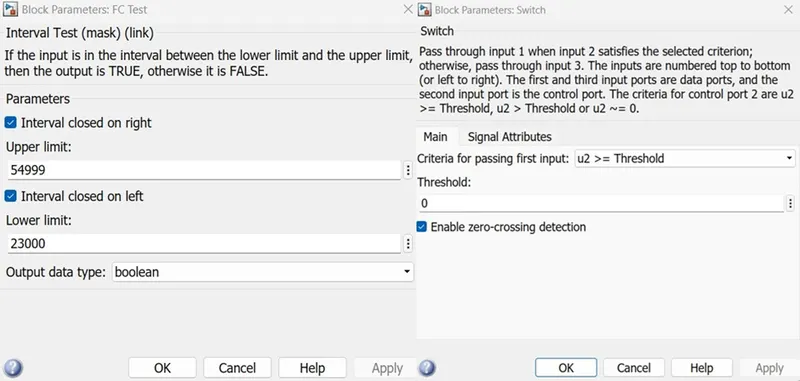
The above picture explains that Battery SOC is >= 35% if the condition satisfies then it will pass 0 else it will pass 1 and when the Batt_Test passes 1 and the SOC condition passes 1 then only the power supply will provide by the Fuel system.
Ultra-Capacitor System: -
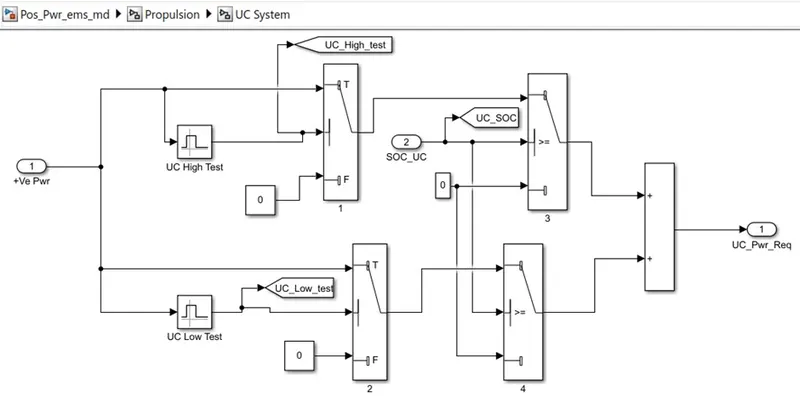
The Ultracapacitor system will deliver the power when the 0-9999 watts is considered as low power demand or it will deliver the power when the 55000 -90000 watts is considered as high-power demand. Any power demand in both will be delivered only when the SOC of the UC system is >0.35%.
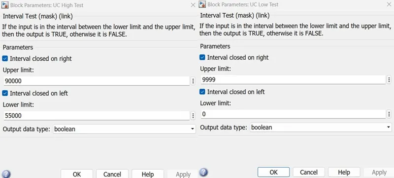
If the UC system’s SOC is <35% then the same power demand will be delivered by the Fuel cell system back to the UC system.
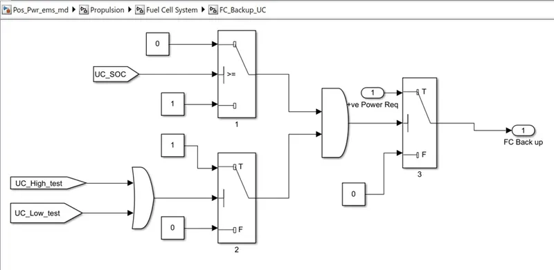
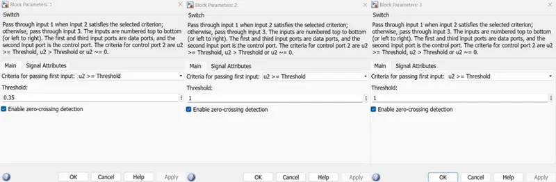
Either the Low power range or the High-power range demand getting as the input then the switch will pass 1 and when the UC SOC is <35% switch will pass 1 when both states were in on condition then the required power demand will be delivered by the FC system.
Fuel Cell System: -
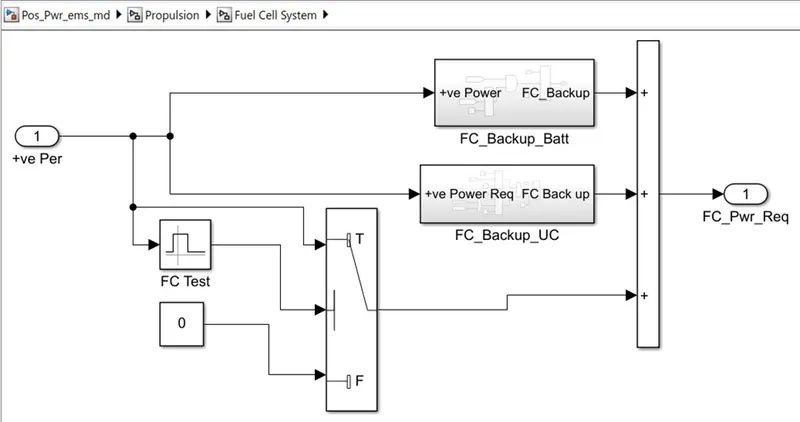
The Fuel cell system will deliver when the power demand is in the range of 23000-54999 watts as well as when the SOC of the UC system and SOC of the Battery system is <35%.
When this condition happened then the backup system of Battery and UC will come into the picture and the total power demand of the system will be provided by the Fuel cell system.
The Overall Model of the Propulsion Power EMS
OUTPUTS
Case-1:
- SOC_UC =0.35
- SOC_Batt=0.35
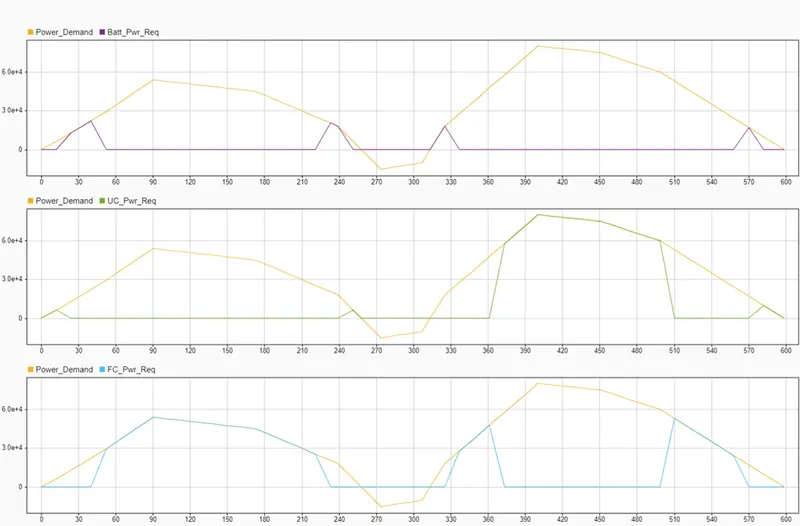
In this case, since the SOC of Both UC and Battery is 35% the power demand is shared by three energy sources as per the power range limitations of the system.
Case2:
- SOC_UC =0.35
- SOC_Batt=0.34
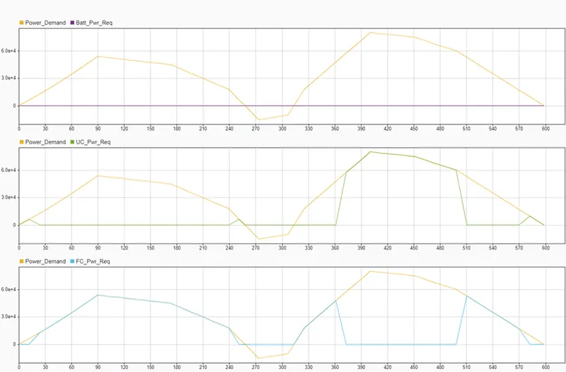
In this case, the SOC of UC is 35% and the Battery is <35% the power demand is shared by UC and FC systems. UC system delivered the power within its limitations and the FC delivered power within its limitations and delivered backup power that the power demand needs to deliver by the battery system.
Case3:
- SOC_UC =0.34
- SOC_Batt=0.35
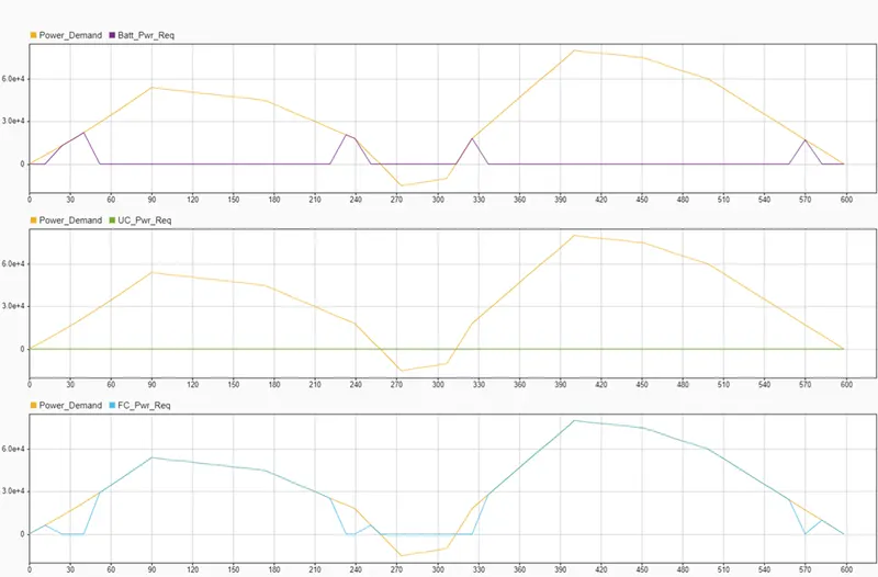
In this case, the SOC of UC is <35% and the Battery is 35% the power demand is shared by Battery and FC systems. The battery system delivered the power within its limitations and the FC delivered power within its limitations and delivered backup power that the power demand needs to deliver by the UC system.
Case4:
- SOC_UC =0.34
- SOC_Batt=0.34
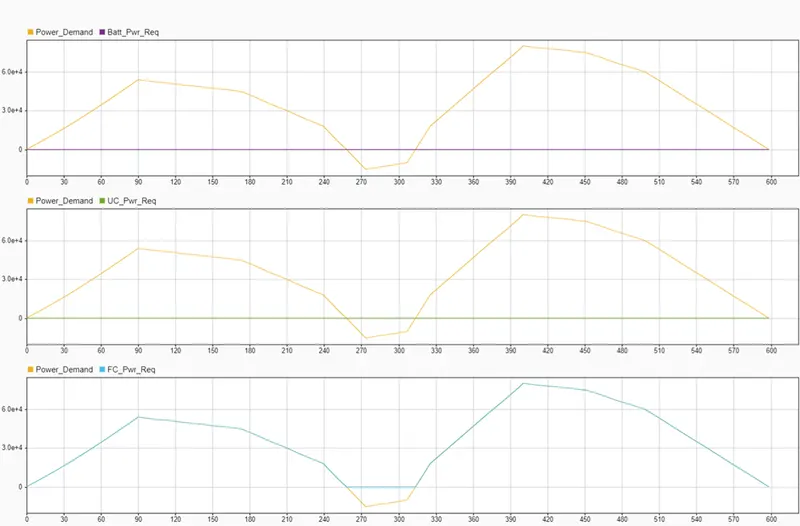
In this case, the SOC of UC and Battery is <35% so the FC system delivered the total power demand, it is a backup source when the other system were unable to deliver the power to the system in their limitation regions.
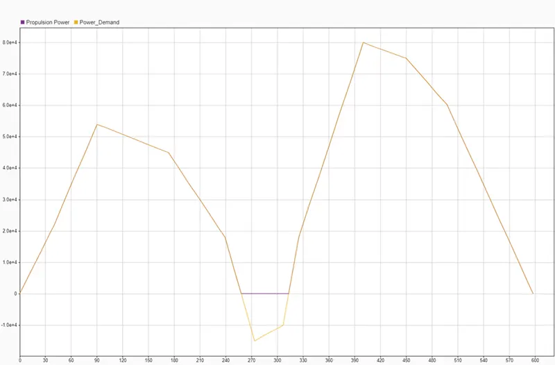
The above picture explains the Propulsion power and regeneration power of the total power demand.