Project - Speed Control of a Direct Current (DC) motor
Project - Speed Control of a Direct Current (DC) motor
MOTOR Schematics
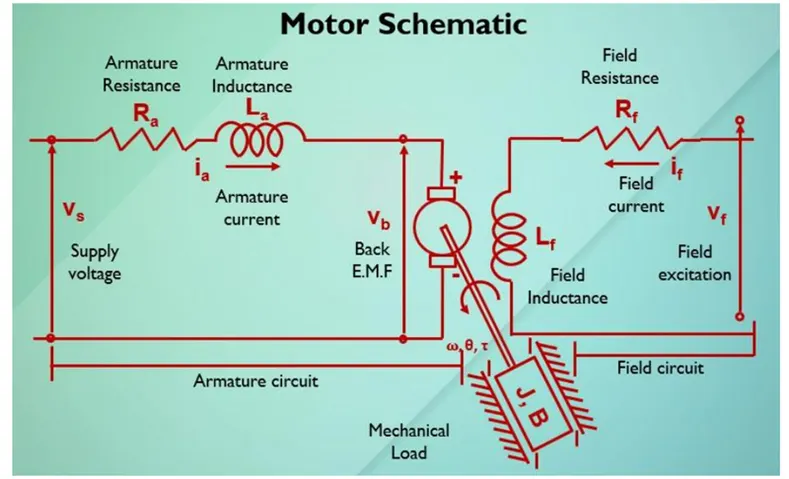
By applying Kirchhoff’s law of voltage
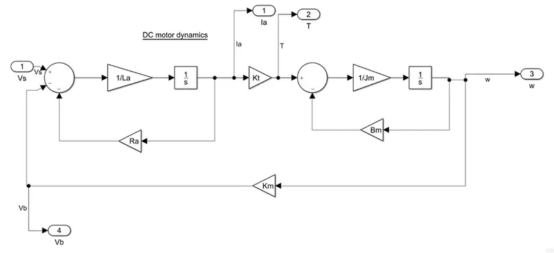
Vs= Ra*Ia + La*(d(Ia)/dt) +Vb
Vb= Km*(d(θ)/dt); T=Kt*Ia
Here Km & Kt are the back emf and torque constants respectively
Angular velocity ‘w’=. θ
The open loop transfer function for the motor speed ‘w’ & supply voltage ‘Vs’ can be derived as
W(s)/Vs(s) = Kt/[(J*La) *s^2 +(J*Ra+B*La) *s+(B*Ra+Kt*Km)]
The state space model for poles
d/dt [. Θ; t] = [-B/J Kt/J; -Km/La -Ra/La] [. Θ; t] + [0; 1/La] Vs
y = [1 0] [. Θ; t]
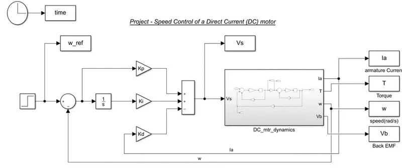
The Simulation Model of the DC Motor along with the PID controller to control the speed of the motor
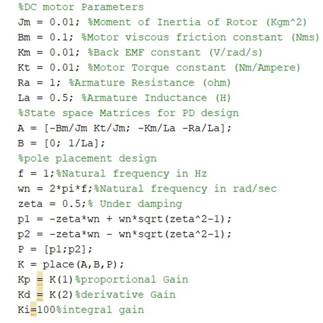
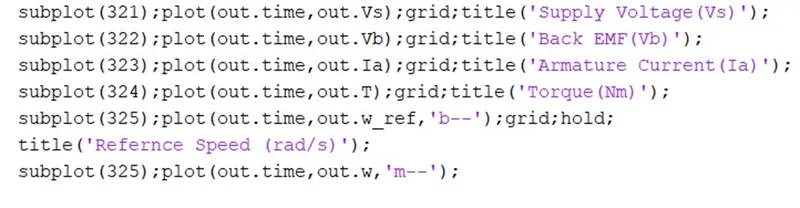
Case:1
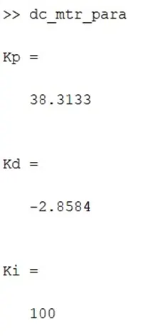
The response of the DC motor by the PID controller, Kp, and Kd was taken from the Poles placement method, and Ki was taken as a random value to observe the response
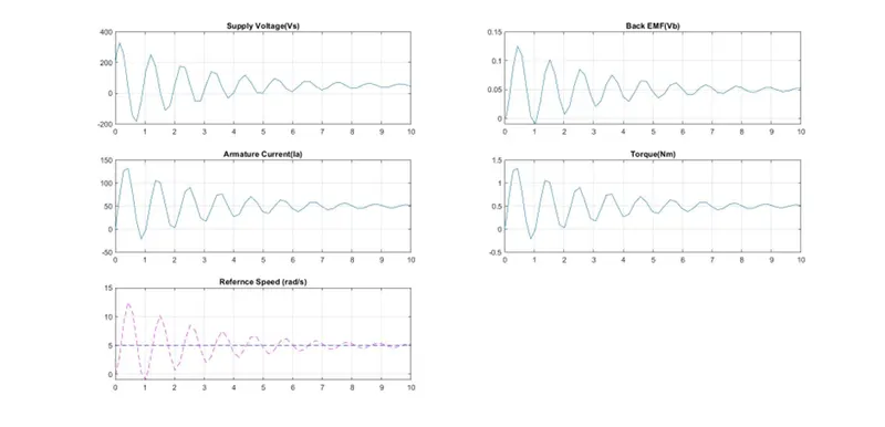
With the taken PID gain values the system is able to achieve the reference signal at the end of the time period. Which is unstable control of the system.
Case:2
In case 1 we can see that more overshoot due to the high Ki value so we decrease the Ki value to
Ki =10, kept Kp and Kd as same.
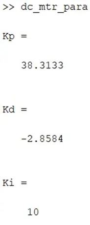
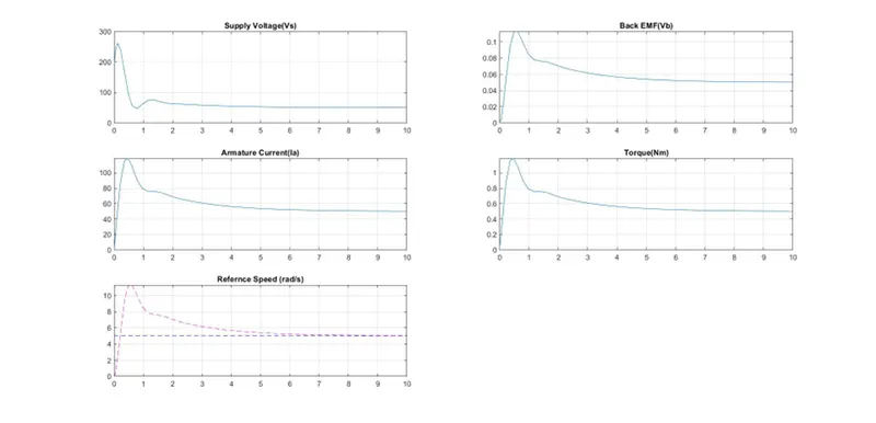
From the above response found that improved rise time and settling time but overshoot is high.
To reduce the overshoot as well as settling time we will tune Ki, Kp, Kd gain values.
Case:3
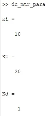
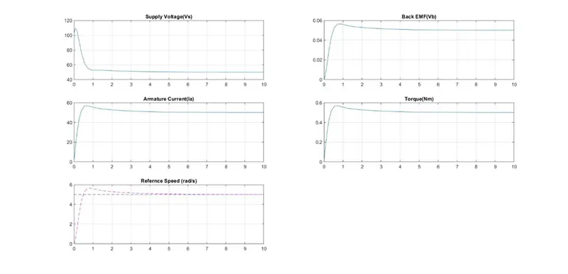
By tuning the Kp and Kd values accordingly the feedback response improved that overshoot almost reduced to range of 5% -10%.
By further tuning we can achieve the better results
Case:4
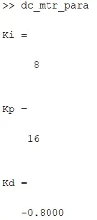
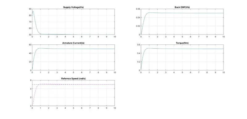
After further tuning, the response achieved
- Settling time < 2s
- Overshoot <5%
- Steady State error <1%
The tuning of Ki, Kp, and Kd values and the effect on the response will be as in the below data.
|
Closed-loop system |
Rise time |
Overshoot |
Settling time |
Steady-state error |
|
Kp |
Decrease |
Increase |
Small change |
Decrease |
|
Ki |
Decrease |
Increase |
Increase |
Decrease |
|
Kd |
Small change |
Decrease |
Decrease |
No-change |
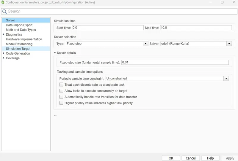
Model Configuration