Week - 4
Q1.
Implement control logic of a “washing machine” using State flow as per the given sequence:
- If the power supply is available, the system gets activated
- If the Water supply is not available, stop the process & indicate through LED
- Soaking time should be 200s followed by Washing time of 100s.
- Then rinsing happens for the next 20s & dryer runs for 50s
After all the processes have been completed turn on the finished LED
SOL: -
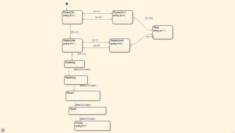
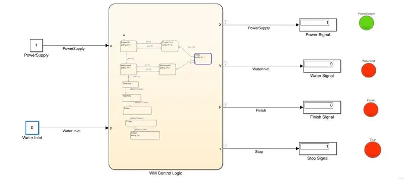
Control Logic of Washing Machine using state flow with given conditions as shown below
Explanation:
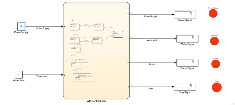
When the Power supply is ‘x=1’ State of the Machine is Power on, if ‘x=0’ control will flow to the Stop state. When the Machine is powered on then logic will check the water inlet, if ‘y=1’ then the control will follow the machine running logic till it reaches the Finish state ‘F=1’. If ‘y=0’ then control will flow to the stop state.
Simulink Model:
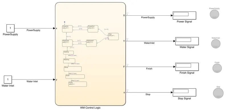
Run the simulation for the infinite time period with the input signal of x=1, y=1 which will result in green-lighting of the Power, Water, and Finish lamps.
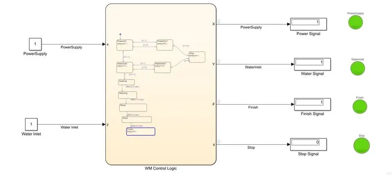
Now, we will check by cutting the water supply y=0, which will result in the red-lighting of the Water, Finish, and Stop lamp.
Now, we will check by cutting the power supply y=0, which will result in the red-lighting of the Power, Water, Finish, and Stop lamp.
Q2.
Make a Simulink chart for the “Gear shift” logic as per the below conditions:
Speed Range(km/h) Gear
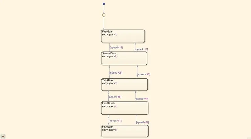
0 to 15 1
16 to 25 2
26 to 40 3
41 to 60 4
Above 61 5
Give speed input while the simulation is running & display the gear number.
SOL: -
The control logic of the Gear shift with the given speed range and gear number is shown below
The Simulink model of the Gearshift is shown below
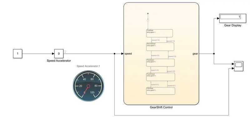
Components used in Gearshift Simulink used
- Constant Block
- Slider gain
- Display
- Scope
- Custom Gauge
Explanation: The designed rated speed of the given model is (0-100) kmph when we vary the speed in the slider gain accordingly the control flow will flow through the logic and display the state of gear in the display. Here we have connected the custom gauge to slider gain to visualize the varying speed. Both speed signal and gear signal were connected to the scope to visualize the real-time sampling will simulation.
Run the simulation for an infinite time period and the following were the simulation results accordingly
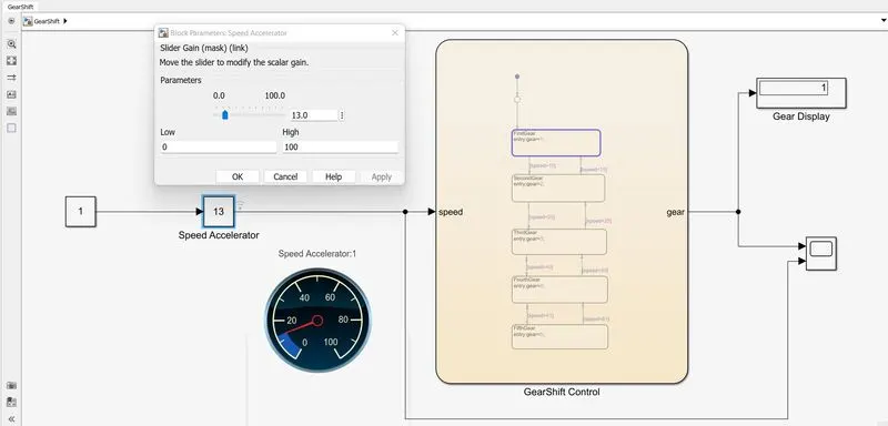
Set the speed at 13 kmph and observed that gear state=1
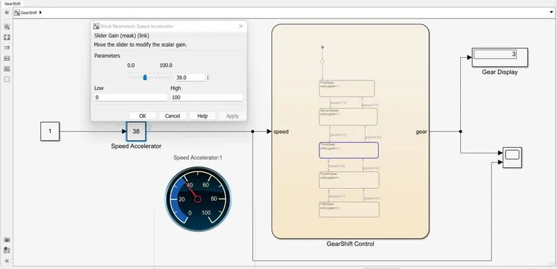
Set the speed at 38 kmph and observed that gear state=3
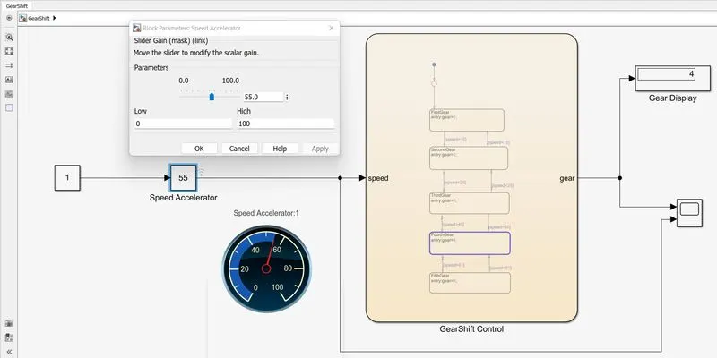
Set the speed at 55 kmph and observed that gear state=4
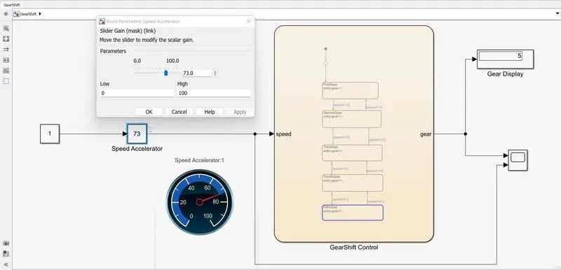
Set the speed at 73 kmph and observed that gear state=5
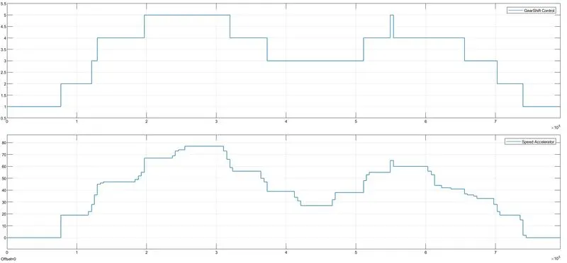
The scope results will simulation as shown below
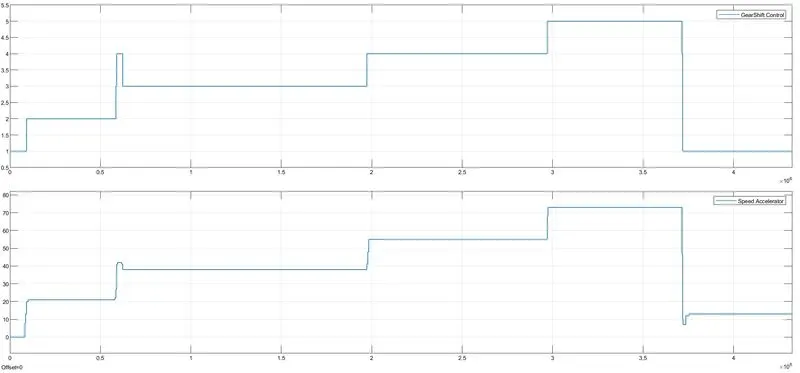
The below scope was when the speed varied very dynamically