Week 8 Challenge
Aim: - Build the Ultracapacitor model and load the parameters of the UC so that we will get outputs as current, SOC, and Voltage.
Ultracapacitor: An ultracapacitor, also known as a supercapacitor, or electrochemical capacitor, is a device for storing electrical energy. ultracapacitors store energy electrostatically, like a regular capacitor, not chemically like a battery - there is a dielectric separator dividing the electrolyte, also like a capacitor.
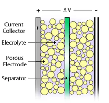
The small separation between electrodes permitted by this structure leads to a much higher energy storage density than a normal capacitor. Whilst an ultracapacitor stores less energy than an equivalently sized battery, it can release it much quicker, as the discharge is not dependent on a chemical reaction taking place.
Because no physical or chemical changes occur when the charge is stored, ultracapacitors can also be used many times over without degradation.
Equations Governed for UC Model:
- The SOC equation:
SOC= ∫ (UC_Current * UC_eff)/UC_Charge(Q) dt
The current flowing through the circuit when integrated gives the charge flown through the circuit. Taking a ratio of it over the total charge capacity gives SOC.
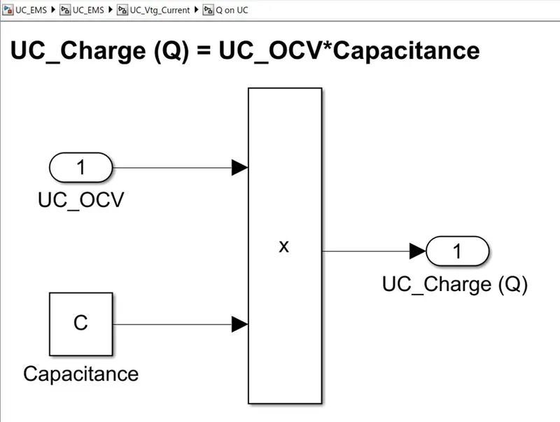
- Total Charge capacity(Q) depends on the capacitance which is the charge storage capacity measured in Farads.
UC_Charge (Q) = UC_OCV*Capacitance
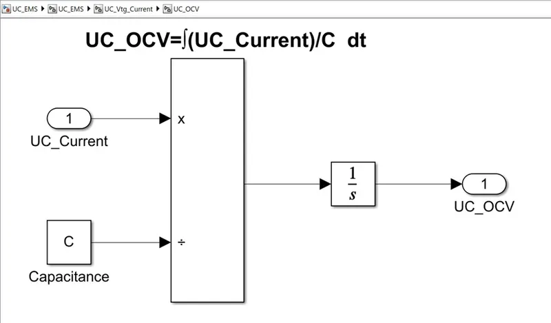
- Open Circuit Voltage(OCV) is a measure of the electric field between the plates.
UC_OCV=∫(UC_Current)/C dt
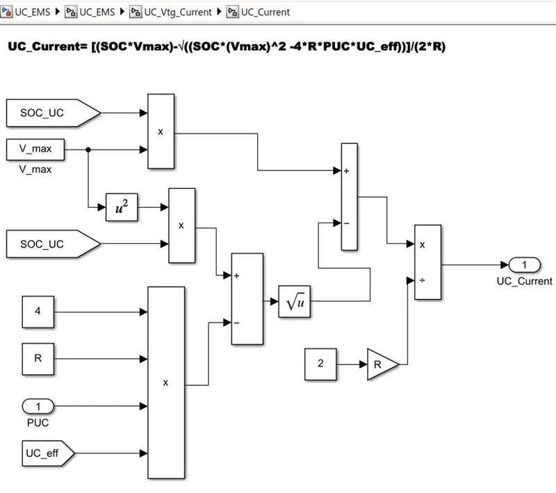
- The current consumed is calculated which is fed into a SOC calculation Block. The SOC is then calculated based on the amount of current drawn and pushed back into UC.
UC_Current= [(SOC*Vmax)-√((SOC*(Vmax)^2 -4*R*PUC*UC_eff))]/(2*R)
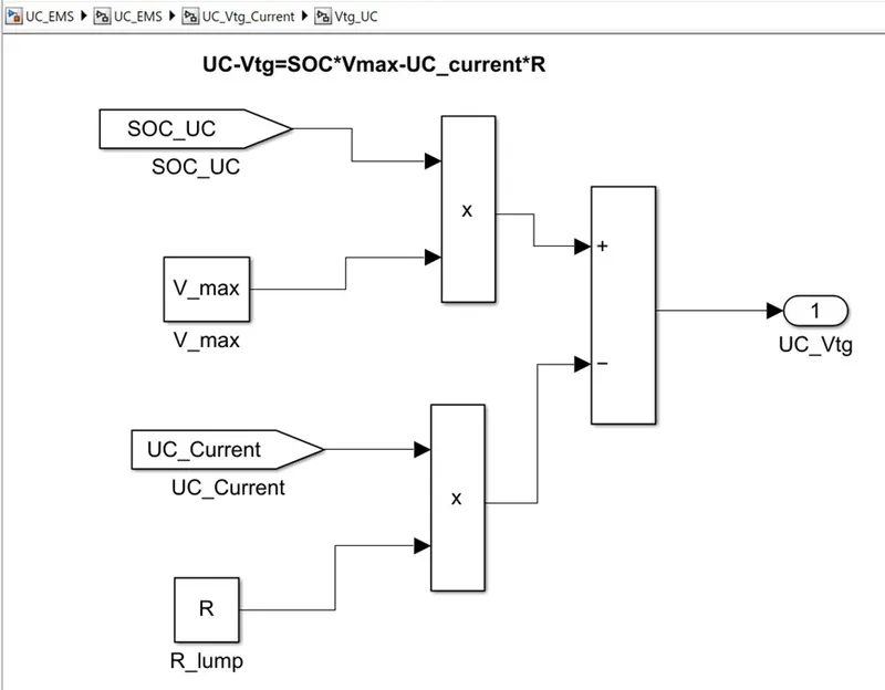
- Output Voltage of a UC depends on the SOC, Max voltage of the UC provided by the OEM and current of the UC along with lumped resistance of the UC
UC-Vtg=SOC*Vmax-UC_current*R
Steps Involved in Modelling of UC Model
Step:1
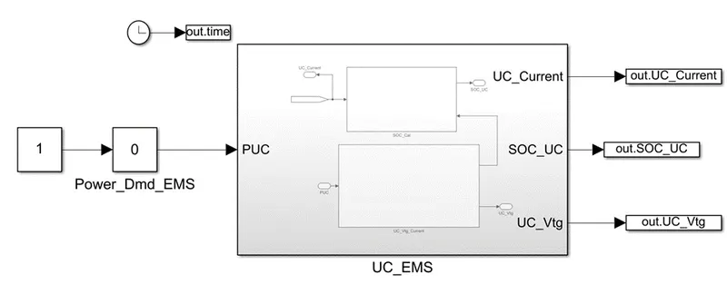
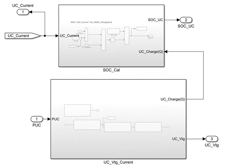
The UC_EMS which receives the power demand from EMS and accordingly UC will perform charge and discharge and will provide the outputs as current, SOC, and Voltage.
The UC_EMS block consists of two subsystems which are SOC calculation and another one is voltage and current calculation.
Step:2
SOC Calculation
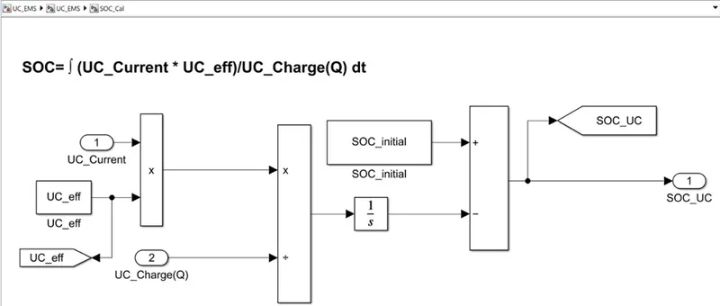
For SOC calculation here we defined the Initial SOC of the UC system if the discharge happens the current SOC will deduct from the initial SOC else while charging the current SOC will add up to the initial SOC.
Step:3
UC Voltage and current calculation Block
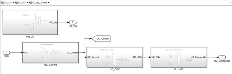
UC-Current
UC-OCV
UC-Q
UC-Voltage
Parameters load to The Model

Model Parameters
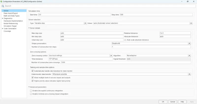
To avoid errors typical causes can be divided by zero (1/0 = inf) or general unstable dynamics that quickly blow up over time. Changed the Modelling parameters
Type: Fixed step to Variable-step
Solver: consider as auto, while simulation it will pick ode15s (stiff/NDF).
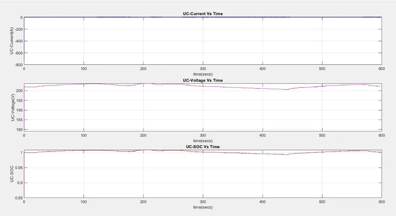
Output Plots Script
f1=figure;
subplot(3,1,1);plot(out.time,out.UC_Current,'b');grid;
xlabel('time(secs)');ylabel('UC-Current(A)');
title('UC-Current Vs Time');
subplot(3,1,2);plot(out.time,out.UC_Vtg,'m');grid;
xlabel('time(secs)');ylabel('UC-Voltage(V)');
title('UC-Voltage Vs Time');
subplot(3,1,3);plot(out.time,out.SOC_UC,'r');grid;
xlabel('time(secs)');ylabel('UC-SOC');
title('UC-SOC Vs Time');
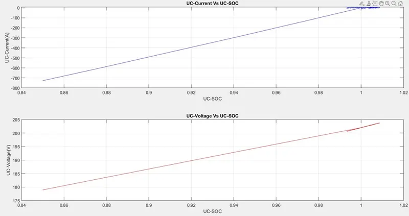
f2=figure;
subplot(2,1,1);plot(out.SOC_UC,out.UC_Current,'b');grid;
xlabel('UC-SOC');ylabel('UC-Current(A)');
title('UC-Current Vs UC-SOC');
subplot(2,1,2);plot(out.SOC_UC,out.UC_Vtg,'r');grid;
xlabel('UC-SOC');ylabel('UC-Voltage(V)');
title('UC-Voltage Vs UC-SOC');
Procedure for Simulation
First, run the Parameter file and run the model file then run the plots file to visualize the outputs.
When the simulation of the model is progressing, vary the slider of the slider gain which is arranged in the range of -10000 to 10000 watts so that charging and discharging can be observed.
Results