Project 1
AIM: -
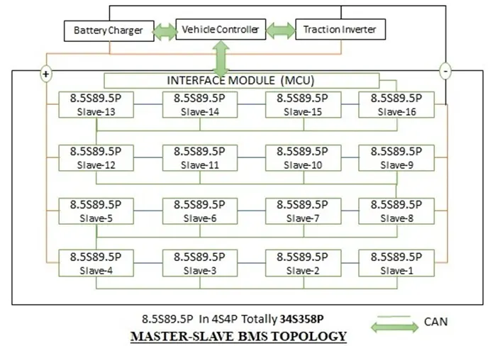
Designing the battery pack configuration with a capacity of 150 kW with 120 V for a car. The Battery pack with a cell capacity of 3500 mAh and a 3.6V nominal NMC chemistry cell. Drawing the BMS topology as per the requirement.
THEORY: -
Cell to Pack is all about reducing cost and increasing the volumetric density of battery packs. This is primarily aimed at road vehicle battery design.
Conventional battery pack design has taken the form:
Cell -> Module -> Pack
This means we add material to make the module strong enough to be handled, it needs fixings and space around the modules for build tolerances. Hence, modules have been growing in size:
Cell -> Large Module -> Pack
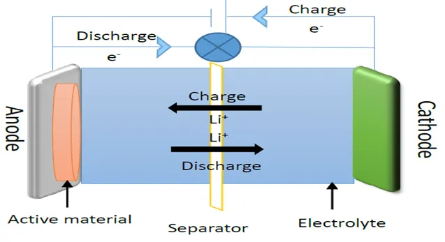
A battery is made up of an anode, cathode, separator, electrolyte, and two current collectors (positive and negative). The anode and cathode store the lithium. The electrolyte carries positively charged lithium ions from the anode to the cathode and vice versa through the separator. The movement of the lithium ions creates free electrons in the anode which creates a charge at the positive current collector. The electrical current then flows from the current collector through a device being powered (cell phone, computer, etc.) to the negative current collector. The separator blocks the flow of electrons inside the battery.
CHARGE/DISCHARGE
While the battery is discharging and providing an electric current, the anode releases lithium ions to the cathode, generating a flow of electrons from one side to the other. When plugging in the device, the opposite happens: Lithium ions are released by the cathode and received by the anode.
Steps involved in Battery Pack Construction
- Cell level Assembly
- Module Level Assembly
- Battery pack level Assembly
In cell-level assembly connecting the cells in series or parallel or both and this combination of cells is known as a Module. Each module is connected in series with wires and busbars.
Number of cells in series = Rated Motor Voltage/ Nominal cell voltage
Number of cells in Parallel = Motor Continuous Current/ Cell nominal capacity
The rounding off the number of cells in series and parallel is an important aspect
Rounding Off the Number of Cells in Series
Condition-1: Battery Maximum Voltage > Motor Nominal Voltage = round off to the lower digit.
Condition-2: Battery Maximum voltage <Motor Maximum Voltage = round off to the Higher digit.
Condition-3: Battery Minimum voltage > Motor Minimum Voltage = round off to the lower digit.
Condition-4: Battery Minimum voltage < Motor Minimum Voltage = round off to the Higher digit.
Rounding Off the Number of Cells in Parallel
Condition-1: Round off > 1C rate = Select the Round Off
Condition-2: Round off < Motor Nominal Voltage = round off to the Higher digit.
Condition-3: Individual Cell Peak Current > Cell Max discharge current = round off to the Higher digit.
Condition-4: Individual Cell Peak Current < Cell Max discharge current =Select the cell.
Individual Cell Peak Current = Load Peak Current / Number of cells in parallel.
CALCULATIONS
Given Battery Pack Capacity = 150kW
Battery Pack Maximum Voltage =120V
Maximum current = 150kW/120V = 1250A
Cell Capacity =3500 mAh =3.5Ah
Cell Nominal Voltage =3.6V
Cell Capacity in Wh = (Cell capacity in mAh * Cell Nominal Voltage) /1000
= 12.6Wh
Cell Discharge current = 12.6/3.6 = 3.5A
The given cell is at a 1C rate.
The number of cells in series = 120V /3.6 V = 33.33
Case-1
Round off to 34
Nominal Battery Voltage =Cell nominal voltage *34 = 34*3.6= 122.4V
Maximum Battery Voltage = Cell Maximum voltage *34=4.2*34=142.8V
Minimum Battery Voltage = Cell minimum voltage* 34= 2.7*34 = 91.8V
Case-2
Round off to 33
Nominal Battery Voltage =Cell nominal voltage *33 = 33*3.6= 118.8V
Maximum Battery Voltage = Cell Maximum voltage *33=4.2*33=138.6V
Minimum Battery Voltage = Cell minimum voltage* 33= 2.7*33 = 89.1V
|
Battery Vtg |
Case-1 |
Case-2 |
Data Sheet |
|
Vnom |
122.4 |
118.8 |
120 |
|
Vmax |
142.8 |
138.6 |
|
|
Vmin |
91.8 |
89.1 |
It is always better to have more voltage, so we can pick case-1 which is 34 cells in series
Number of cells in parallel = Battery Max current / Cell nominal capacity = 1250/3.5= 357.14
Case-1
Round off to 357
Individual cell peak current = Load peak current / No of cells in parallel =1250/357= 3.501
Case-2
Round off to 358
Individual cell peak current = Load peak current / No of cells in parallel =1250/358 = 3.491
Individual cell peak current case-1 is >cell discharge current. So that the number of parallel cells is 358.
Therefore, the configuration of the Battery would be 34S358P.
Battery Configuration details
|
Battery pack Capacity |
150000 |
W |
|
Vnom |
120 |
V |
|
Inom |
1250 |
A |
|
single cell capacity |
3500 |
mAh |
|
3.5 |
AH |
|
|
NO OF parallel cells required |
357.1428571 |
nos |
|
358 |
nos |
|
|
358 cells at 3.6V |
||
|
single cell nominal battery |
3.6 |
V |
|
battery nominal voltage |
120 |
V |
|
no series cell required |
33.33333333 |
nos |
|
34 |
nos |
|
|
4 |
sets |
|
|
8.5 |
series/set |
|
|
no of parallel cells as per the set |
89.5 |
parallel/set |
|
Configuration of each Set |
||
|
Parallel |
89.5 |
|
|
Series |
8.5 |
|
|
Current(A) |
313.25 |
|
|
Voltage(V) |
30.6 |
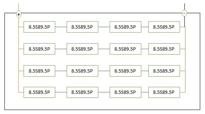
We will connect the 4 sets of 8.5S89.5P in 4S4P so that we will get the Max voltage of 122.4V and the Max current of 1253A as shown below
The BMS topology for this battery pack