Project 1 - Loss calculation for a DC/DC converter-MATLAB
EV REFRESHER
Project-1: Loss calculation for a DC_DC converter-MATLAB
Aim: - Calculating the loss that occurred in the components of the DC-DC converter [Buck converter] including the power switching device, diode, etc, and calculating the efficiency of the converter.
Non-ideal Buck Converter:
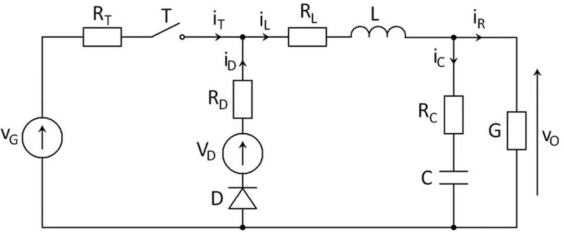
The circuit is composed of the internal resistance of the supply battery, Switching device & Diode, and low pass filter with resistive load.
Parameters for designing of Model:
Vin=50;%input vtg
Vout=25;%output vtg
L=400e-6;%Filter Inductance
C=500e-6;%Filter Capacitance
R=10;%Resistive Load
kp=0;%proportional gain
ki=0.338661;%integral gain
rL=10e-3;% LPF Inductive Resistance
rC=2e-3;%LPF Capacitive Resistance
rb=8e-3;% Battery Internal Resistance
fsw=20e3;%Switching Frequency
All the parameters were initialized in Model Properties.
Procedure:
The DC voltage source is connected to the MOSFET in series and parallel to the diode then connected to the low pass filter (RL in series and RC in parallel to the load resistance). The voltage Measurement is taken at the resistance load given to the Summation block which will generate the error with the reference of Vout. The error is fed to the PI controller and improves the duty cycle that can be fed to the Pulse generator, which will generate the pulse for the turn-on and turn-off of the MOSFET.
The duty cycle of the converter is given by: d = Vout/Vin.
The output power, that is, the product of the output voltage and current, is also the input power, by the law of conservation of energy but the loss will generate by the components in the circuit such as:
Conduction loss:
The power loss in the MOSFET is due to parasitic components (resistance, inductance, capacitance) which were in the flow of DC current in the circuit. It can be estimated from the output current, On- resistance, and on-duty cycle.
P_cond = Iout*R*d
Switching Loss:
When the MOSFET is turned ON and OFF alternately, a loss is generated during the transition of the switching. It can be estimated by
P_sw =1/2*Vin*Iout*(tr*f_sw)
Diode Loss:
When the MOSFET is a turn-off, the diode is determined by the forward direction voltage of the diode and its value becomes large. Since the diode conducts the current when the high-side MOSFET is OFF, the loss can be estimated with the following equation.
Pd = Iout × 𝑉f × (1 − d).
Loss in the capacitor:
The capacitor―including series resistance, leakage, and dielectric loss―these losses are simplified into a general loss model as equivalent series resistance (ESR). The power loss in the capacitor is calculated by multiplying the ESR by the square of the RMS value of the AC current flowing through the capacitor.
P_cap(ESR)= (I_C)2*ESR
The RMS current in the input capacitor is complex, but it can be estimated with the following equation
IC(RMS) = Iout*sqrt[(Vin-Vout)*Vout/Vin]
Conduction loss in the inductor
The conduction loss is generated by the DC resistance (DCR) of the winding that forms the inductor. The DCR increases as the wire length increases; on the other hand, it decreases as the wire cross-section increases. If this trend is applied to the inductor parts, the DCR increases as the inductance value increases and decreases as the case size increases.
The conduction loss of the inductor can be estimated as
PL(DCR)=IOUT2 *DCR
𝐼𝑂𝑈𝑇: Output current [𝐴]
𝐷𝐶𝑅: Inductor direct current resistance [Ω]
The Simulation Model of Non-ideal Buck Converter:
Blocks used for modeling
- DC Voltage source
- MOSFET
- Diode
- series RLC branch (Rb, RL, RC, R_load)
- Voltage and current measurement block
- PWM generator
- Display & Scope
- Bus selector
- Power-gui
- Constant
- Sum
- PI controller
- Pulse Generator DC-DC
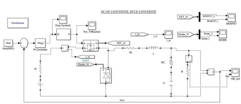
V&I_OUT: -
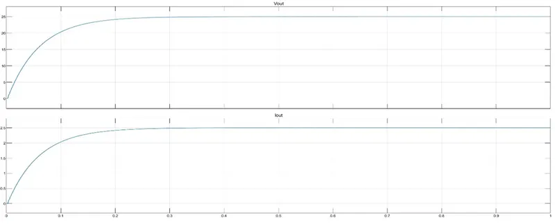
Vout=25V, Iout=2.5A
Diode Forward Voltage (Vf): -
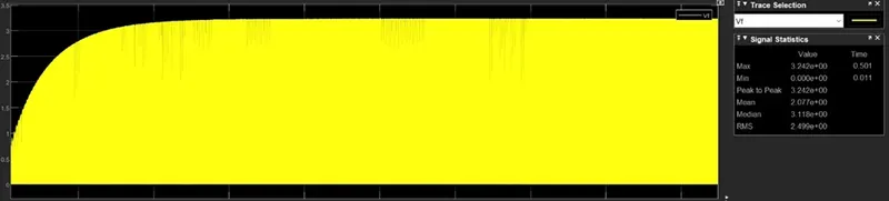
Vf=3.242 V
Duty Cycle(d):
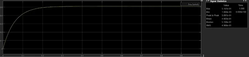
d=0.5107
Rise Time(tr): -
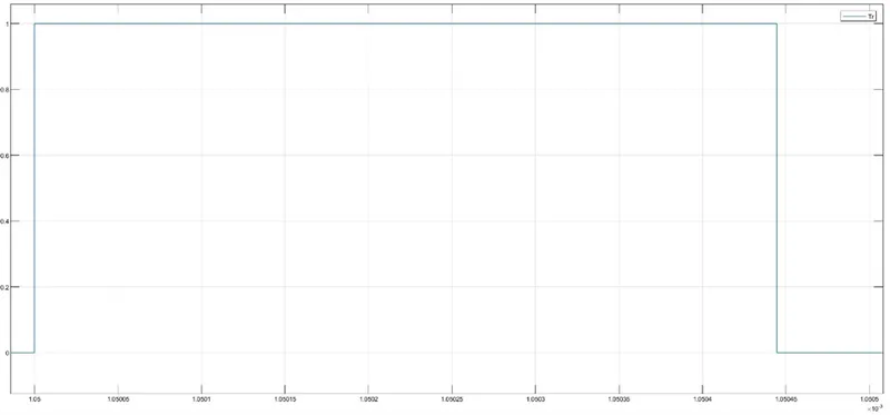
Tr=tr2-tr1 = = (1.0005048-1.0005) *10^-3= 4.8e-09
Losses and Performance Calculations: -
|
Losses and Performance Calculator |
Loss In watts |
Measurements |
Values |
||
|
Conduction loss in MOSFET |
12.7675 |
Vin |
50 |
||
|
Switching Loss: |
6.00 |
Vout |
25 |
||
|
Diode Loss: |
4.183515 |
Iout |
2.5 |
||
|
Loss in the capacitor: |
0.16 |
F_sw |
2.00E+07 |
||
|
IC(RMS) = Iout*sqrt[(Vin-Vout)*Vout/Vin] in (A) |
8.838835 |
Tr |
4.80E-09 |
||
|
Conduction loss in the inductor: |
0.06 |
d |
0.5107 |
||
|
Power_Loss= |
23.17 |
Vf |
3.42 |
||
|
Power_ Out |
62.5 |
ESR |
2.00E-03 |
||
|
Power_In= |
85.67 |
DCR |
1.00E-02 |
||
|
Efficency |
72.95% |
R |
10 |
Conclusion:
The designed Non-Ideal buck converter produced 23.17 W of power loss with 72.95% performance efficency.
Note:-
Excel calculator and model file attached.