Week-7 Challenge: DC Motor Control
Q1.
- Explain a MATLAB demo model named ‘Speed control of a DC motor using BJT H-bridge’.
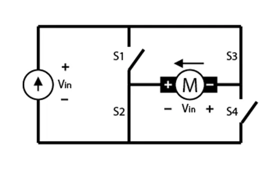
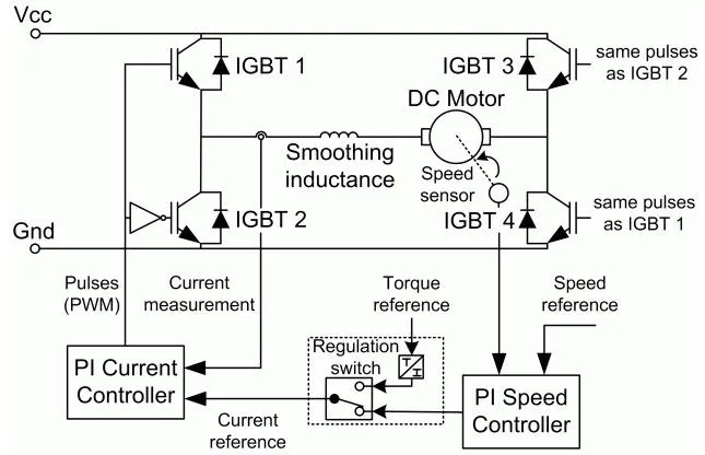
An H-bridge is an electronic circuit that switches the polarity of a voltage applied to a load. It is used to allow DC motors to run forwards or backward. The name is derived from its common schematic diagram representation, with four switching elements configured as the branches of a letter "H" and the load connected as the cross-bar as shown in below block diagram.
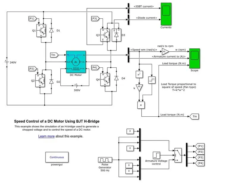
The H-bridge consists of four BJT/Diode pairs (BJT simulated by IGBT models). Two transistors are switched simultaneously.
Any power switch will have 3 terminals which are connected to +ve of source and one is connected to ground(-ve) and the third terminal through which we give pulse or control signals to switch on the device.
Load is connected between the 2 branches of 4 switches
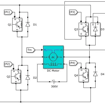
Need to make sure that current should flow from the +ve potential to through the switches to load and from load to -ve potential to close the circuit. Also, make sure about the switches are turned on & turned off properly and there is no kind of short circuit happening.
so we should not trigger the Q1&Q2 together because both were connected to the same branch, if Q1&Q2 gets triggered at the same time, it will create a very low resistance path which will result in a short circuit, the same will be applicable for Q3&Q4 and Q1&Q3.
Condition:1
If Switch 1 (Q1)and 4(Q4) are closed, then the current will flow from the left to right
If you close switch 1(Q1) and switch 4(Q4), the current will flow from the source, through switch 1(Q1), and then through the load, then through switch 4(Q4), and then back to the load.
In this condition, the motor will rotate in the forward direction.
Condition:2
If Switch 3(Q3) and 2(Q2) are closed, then the current will flow from the right to left
If Switch 2(Q2) and switch 3(Q3) closed. This will cause the current to flow from the source, through switch 3(Q3), and then through the load, then through switch 2(Q2), then back to the load.
In this condition, the motor will rotate in the reverse direction.
Simulink Demo Model:
The Bipolar Junction Transistor (BJT) when used for power switching applications, operates as an IGBT. When it is conducting (BJT operating in the saturated region), a forward voltage Vf is developed between collector and emitter (in the range of 1 V). Therefore, the IGBT block can be used to model the BJT device. The IGBT block does not simulate the gate current controlling the BJT or IGBT. The switch is controlled by a Simulink signal (1/0).
DC Motor used in Model:
The DC motor uses the preset model (5 HP 24V 1750 rpm). It simulates a fan-type load (where Load torque is proportional to the square of speed). The armature average voltage can be varied from 0 to 240 V when the duty cycle (specified in the Pulse Generator block) is varied from 0 to 100%.
The H-bridge consists of four BJT/Diode pairs (BJT simulated by IGBT models). Two transistors are switched simultaneously: Q1 and Q4 or Q2 and Q3. When Q1 and Q4 are fired, a positive voltage is applied to the motor, and diodes D2-D3 operate as free-wheeling diodes when Q1 and Q4 are switched off. When Q2 and Q3 are fired, a negative voltage is applied to the motor, and diodes D1-D4 operate as free-wheeling diodes when Q2 and Q3 are switched off.
Pulse Width Modulation (PWM):
Pulse width modulation reduces the average power delivered by an electrical signal by converting the signal into discrete parts. In the PWM technique, the signal’s energy is distributed through a series of pulses rather than a continuously varying (analog) signal.
PWM signal stays “ON” for a given time and stays “OFF” for a certain time. The percentage of time for which the signal remains “ON” is known as the duty cycle. If the signal is always “ON,” then the signal must have a 100 % duty cycle. The formula to calculate the duty cycle is given as follows:

The average value of the voltage depends on the duty cycle. As a result, the average value can be varied by controlling the width of the “ON” of a pulse.
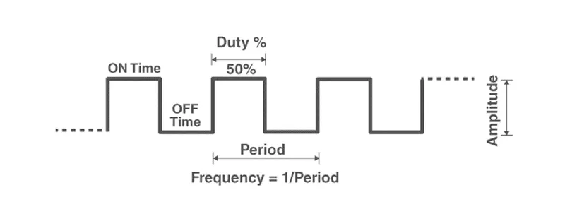
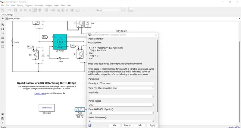
The given pulse generator in the model by a pulse width of 75% with an amplitude of 1 and a period of 2e-3 seconds.
The remaining parameters were considered as default values of the model.
Simulation: The motor starts in the positive direction with a duty cycle of 75% (mean DC voltage of 180V). At t= 0.5 sec., the armature voltage is suddenly reversed and the motor runs in the negative direction.' Scope' shows motor speed, armature current, and load torque and 'Currents' shows currents flowing in BJT Q3 and diode D3.
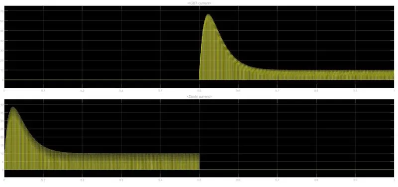
The above waveform outputs of the currents of IGBT and diode show that from 0 to 0.5 time period IGBT current remains 0 and in same time period current is flowing in through the diode. Now from 0.5 to 1 time period, the diode current remains 0 and current is flowing through the IGBT.
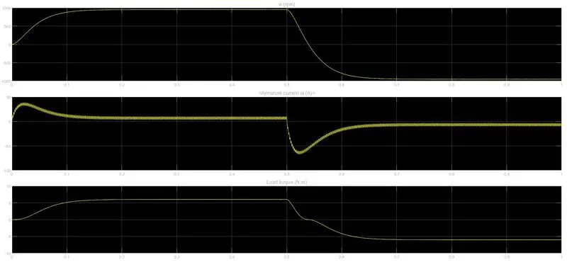
From the above graph, we can see that the speed reaches a maximum speed of 1000 rpm and after a 0.5 time period, it decreases, reaches to -1000rpm.
The armature current starts from 0 and reaches up to 40-45A and it starts decreasing immediately and then reaches 0. Here when the speed is decreasing the armature current starts to flow in the reverse direction and when the speed reaches -1000rpm the current also flows in the negative direction near to 0. Here we can see the spikes in the armature current in both directions.
The Load torque follows the speed in the positive direction and it follows both speed and armature current in the negative direction.
B. Comment on the armature current shoot-up from the scope results.
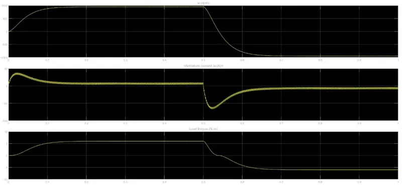 Figure 1 Duty cycle with 75%
In the above graph, we have observed the sudden rise in armature current there we have provided the duty cycle of 75% from the pulse generator. To understand whether the armature current is getting sudden rise or not let us try by changing the duty cycle from 75% to 60%.
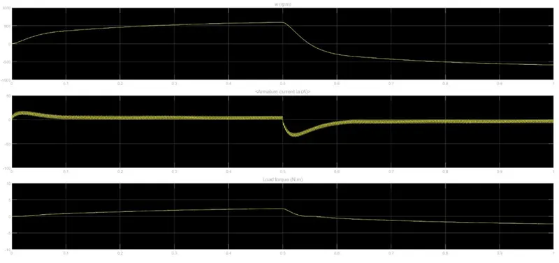 Figure 2 duty cycle of 60%
From the above graph, we can see that rise of armature current is a little less compared to Figure 1. For further understanding, we will reduce the duty cycle to 50%
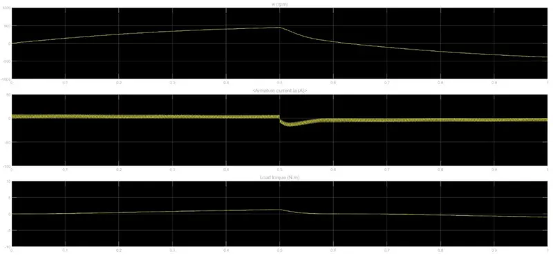 Figure 3 duty cycle of 50%
From figure 3 we can see that there is no sudden rise in the starting of the armature current and if we further reduced the duty cycle from the pulse generator, the rise in the negative axis will also get reduced. We check with a duty cycle of 40%
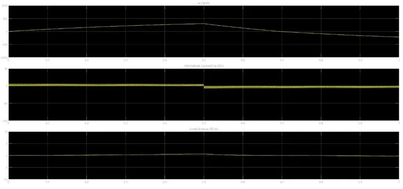 Figure 4 duty cycle of 40%
From figure 4 we can understand that the reduction of the duty cycle will provide a smooth variation in outputs (Speed, armature current, and torque).
Here we have changed the only duty cycle percentage from the pulse generator and the remaining parameters are kept as default.
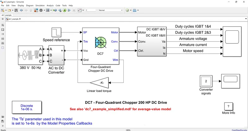
C.Refer to the help section of ‘The Four-Quadrant Chopper DC Drive (DC7) block’. Compare it with the H-bridge model.
Chopper: The chopper is a static power electronics device that converts fixed DC voltage/power to variable DC voltage or power. It is nothing but a high-speed switch that connects and disconnects the load from the source at a high rate to get variable or chopped voltage at the output.
- First-quadrant, or Type-A Chopper
- Second-quadrant, or Type-B Chopper
- Two-quadrant type-a, or Type-C Chopper
- Two-quadrant type-b, or Type-D Chopper
- four-quadrant Chopper, or Type-E Chopper
First-quadrant, or Type-A Chopper:
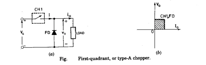
When chopper in ON condition, then Vo=Vs and the direction of flow of current (io) is given by an arrow. Again, when Chopper is in OFF condition, Vo=0, however, the direction of current (io) remains unchanged i.e., it will flow through the freewheeling diode, (FD).
As shown in the Vo-io plot, we can see that the average voltages (Vo) and load current (io) are always positive. Note that power flow in type-A is always from source to load.
This type of chopper is also called a step-down chopper because the output average voltage (Vo) is lesser than that of the input voltage (Vs).
Second-quadrant, or Type-B Chopper
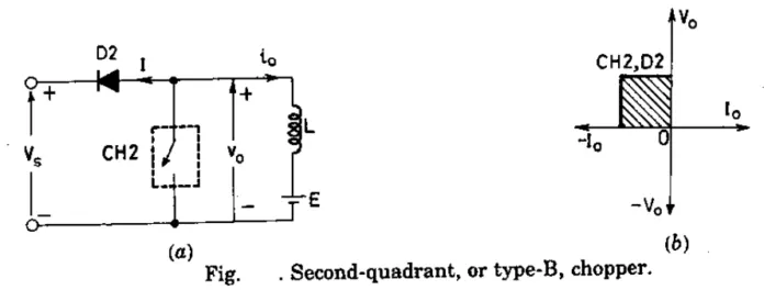
Here, the load must contain the dc source ‘E’, like a battery (or a dc motor) in this chopper. When the chopper (CH2) is in ON condition, Vo=0. But the load voltage ‘E’ will drive a current through ‘L’ and chopper (CH2). The inductance(L) will store energy when the chopper is in Ton Period.
When the chopper is in OFF condition, Vo=E + L di/dt. Here, since the value of Vo exceeds the supply voltage (Vs). As a result, the diode D2 will be forward biased and will be conducted which will allow the power to flow to the source.
Now, the chopper may be in ON or OFF condition, and the current flow (io) will be out of the load, as a result, the current flow will be treated as negative. Here, since Vo is always positive and Io is negative, the power flow will be from load to source.
Lastly, as the average output voltage (Vo) is more than the source or supply voltage, this Type-B Chopper is called a step-up chopper.
Two-quadrant type-a, or Type-C Chopper
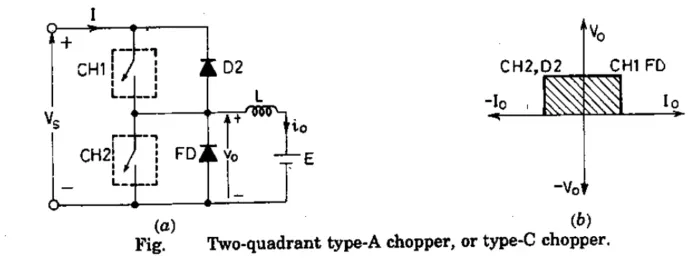
Type-A and Type-B are connected in parallel as shown in the figure. Due to the presence of freewheeling diode FD across the load, the output voltage (Vo) is always positive. When the chopper CH2 is turned ON, the freewheeling diode FD conducts and thus obtaining the output voltage, Vo=0. Similarly, When the chopper CH1 is turned ON, the diode D1 conducts and the output voltage is given by Vo=Vs.
The current io flows in the arrow direction as shown in the figure. Note that the load current can however be in reversed condition. So, we can say that the load current is positive when the chopper CH1 is at ON condition and freewheeling diodes conducts. And, the load current is negative if the chopper CH2 is at OFF condition or when D2 conducts. In other words, chopper CH1 and freewheeling diode FD operate as Type-A choppers in the first quadrant, and similarly, chopper CH2 and D2 operate together as Type-B in the second quadrant.
The average load voltage is always positive but the average load current may be either positive or negative as discussed above. Therefore, power flow may be from the source to load (first-quadrant operation) and from load to a source (second-quadrant operation).
Note that the chopper CH1 and CH2 should not be operated or turned ON at the same time as this would lead to a direct short circuit on the supply lines. This type of chopper is used for monitoring and regenerative braking of a DC motor.
Two-quadrant type-b, or Type-D Chopper
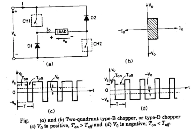
Two-quadrant type-b or Type-D Chopper is shown in the figure. When both the chopper CH1 and CH2 are at ON condition then the output average voltage Vo=Vs. When both the chopper is turned OFF but diodes D1 and D2 conduct, then the output voltage Vo=-Vs. The average output voltage is positive when the chopper turn-on time (Ton) is more than their turned-off (Toff) time i.e., Ton>Toff. Similarly, the average output voltage will be negative when the chopper turn-on time (Ton) is less than their turned-off (Toff) time i.e., Ton<Toff.
The direction of the flow of load current will always remain positive because chopper and diodes can conduct only in the direction as shown in the figure. As the output voltage Vo is reversible, therefore the power flow is also reversible. The operation of this type of chopper characteristic is represented by a hatched area in the first quadrant and fourth quadrant shown in the plots.
Four-quadrant Chopper, or Type-E Chopper
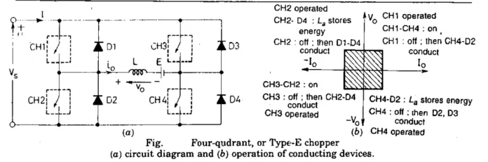
This type of Chopper Circuits consists of four semiconductor switches CH1 to CH4 and four diodes D1 to D4 anti-parallel. The working of this chopper is explained under four quadrants.
First-quadrant: - The operation of the first quadrant is shown in the figure When the CH4 is turned ON, CH3 remains OFF and CH1 gets operated. As CH1 and CH4 are at ON condition, the load voltage is equal to the source voltage (Vo=Vs) and the load current begins to flow in the circuit. When CH1 is turned off, a positive current flow through CH4 and D2. In this way, we can control the load voltage (Vo) and load current (Io).
Second-quadrant: - Here CH1, CH3, and CH4 are kept off and CH2 is being operated. As CH2 is turned ON, reverse (or negative) current flows through L, CH2, D4, and E. Inductance (L) is used to store energy when the CH2 is turned ON. When CH2 is turned off, the current is feedback to the source through diodes D1 and D4. Here output voltage is more than the supply voltage (Vo=Vs). In the second quadrant, the load voltage is positive and the load current is negative. Note that the power feedback is from load to source.
Third-quadrant: - The operation of the third quadrant is shown in the figure. Here, CH1 is kept off, CH2 is kept ON and CH3 is being operated. The polarity of the load emf E is reverse for working in this quadrant. With CH3 being operated, the load gets connected to the source (Vs) so that both load voltage (Vo) and load current (Io) are negative leading to third quadrant operation. When CH3 turned OFF, negative current freewheels through the CH2 and D4. So, in this way, Vo and Io are controlled in the third quadrant.
Fourth-quadrant: - In this quadrant, CH4 is operated and other devices or parts are kept off. Load Emf E must have its reverse polarity for operation in the fourth quadrant as shown in the figure. With CH4 kept ON mode, positive current flows through CH4, D2, L, and E. Here inductance ‘L’ stores energy when CH4 is turned ON. When CH4 is turned off current is feedback to the source through diodes D2 and D3. Here, the load voltage is negative, but the load current is positive leading to the chopper operation in the fourth quadrant. Note that power feedback is from load to source. The operation of conducting devices in the fourth quadrant is shown in the figure.
Comparison between four-quadrant DC chopper and the H-Bridge:
|
four-quadrant DC chopper |
H-Bridge |
|
It can operate in 4 regions (Forward motoring, reverse braking, reverse motoring, and forward braking) |
It can operate only in 2 regions (Forward & Reverse) |
|
It is having two PI regulators (Speed regulator & current regulator) |
No regulator is used in H-Bridge. |
|
Regenerative braking is possible |
Regenerative braking is not possible. |
|
Used for many applications such as circuits used in power flow control & signal applications and electronic switching devices |
Used in robotics applications to allow the dc motor to run forward and backward. |
|
It is an electronic switch that is used to interrupt one signal under the control of another. |
It is an electronic circuit that switches the polarity of the voltage applied to the load. |
|
It will provide better efficiency. |
It will provide low efficiency comparatively. |
MATLAB model of The Four-Quadrant Chopper DC Drive (DC7) block
- Develop a 2-quadrant chopper using Simulink & explain the working of the same with the relevant results.
Abstract: The speed control of the motor by using the chopper circuit in two quadrants region by using the Type-C and Type-D chopper. By using MATLAB & Simulink modeling the drive model of the circuits and explaining of simulation results.
Introduction: The motors were used in many industrial applications requiring variable speed and load characteristics due to ease of control. A chopper drive-based speed control is widely preferred as far as speed control is concerned. Choppers are mostly applied in electric cars, conversion of wind and solar energy, and DC motor regulators. A chopper uses high speed to connect and disconnect from a source load. A fixed DC voltage is applied intermittently to the source load by continuously triggering the power source switch ON/OFF. The period for which the power switch stays ON or OFF is referred to as the chopper’s On and OFF state times, respectively.
The Two-quadrant chopper is a chopper that can operate in quadrants 1&2 and quadrants 1&4. The power can flow from source to load and load to source.
Two Quadrant Chopper:
Chopper: The chopper is a static power electronics device that converts fixed DC voltage/power to variable DC voltage or power. It is nothing but a high-speed switch that connects and disconnects the load from the source at a high rate to get variable or chopped voltage at the output.
Type-C Chopper:
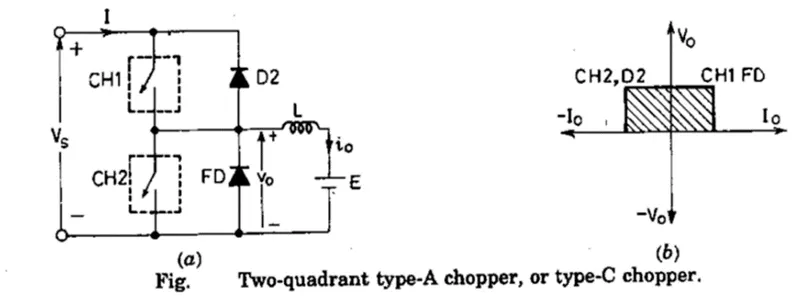
Type-A and Type-B are connected in parallel as shown in the figure. Due to the presence of freewheeling diode FD across the load, the output voltage (Vo) is always positive. When the chopper CH2 is turned ON, the freewheeling diode FD conducts and thus obtaining the output voltage, Vo=0. Similarly, When the chopper CH1 is turned ON, the diode D1 conducts and the output voltage is given by Vo=Vs.
The current io flows in the arrow direction as shown in the figure. Note that the load current can however be in reversed condition. So, we can say that the load current is positive when the chopper CH1 is at ON condition and freewheeling diodes conducts. And, the load current is negative if the chopper CH2 is at OFF condition or when D2 conducts. In other words, chopper CH1 and freewheeling diode FD operate as Type-A choppers in the first quadrant, and similarly, chopper CH2 and D2 operate together as Type-B in the second quadrant.
The average load voltage is always positive but the average load current may be either positive or negative as discussed above. Therefore, power flow may be from the source to load (first-quadrant operation) and from load to a source (second-quadrant operation).
Note that the chopper CH1 and CH2 should not be operated or turned ON at the same time as this would lead to a direct short circuit on the supply lines. This type of chopper is used for monitoring and regenerative braking of a DC motor.
MATLAB Model:
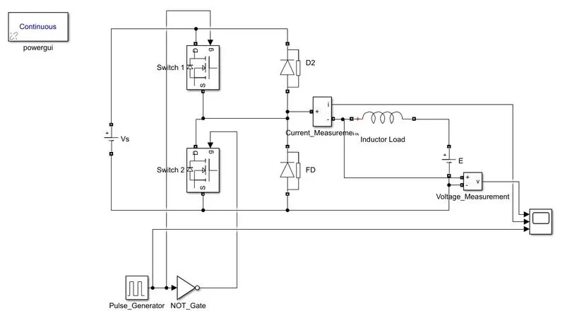
Model Explanation:
- Select the blocks of the MOSFET, diode, Inductor(load), pulse generator, NOT gate, dc supply, voltage & current measurement, and scope.
- By using the NOT gate when switch 1 conducting the switch 2 will in not conduct.
- Made the connections as per the above circuit diagram.
- Considered the Vs=24V, E=12V, Pulse amplitude as 10 with 50% duty cycle.
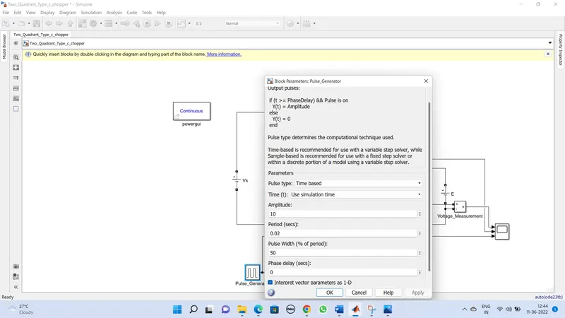
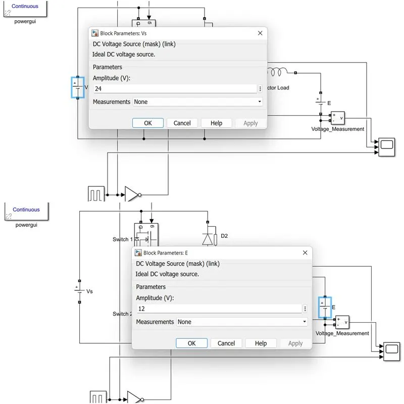 5.Run the simulation for the time period of 0.1 sec. Simulation results show below.
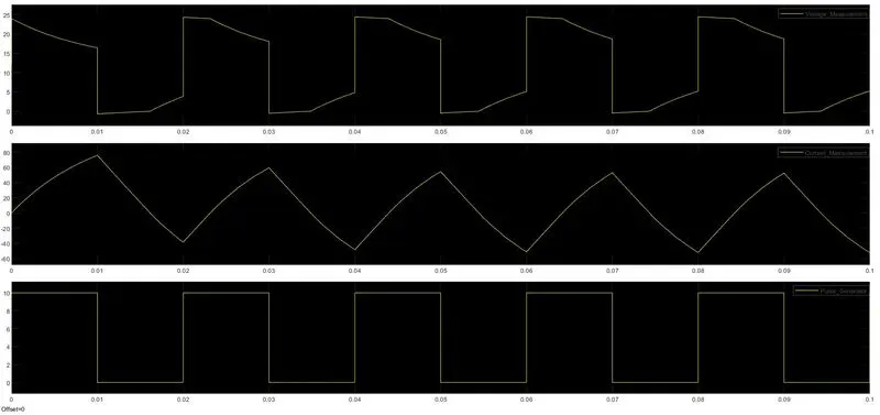
Here we can see that the Load voltage E was plotted in the positive direction and the load current was plotted in both directions. In the operation of this 2-quadrant chopper, Voltage is positive, and current is both positive and negative.
Type-D Chopper:
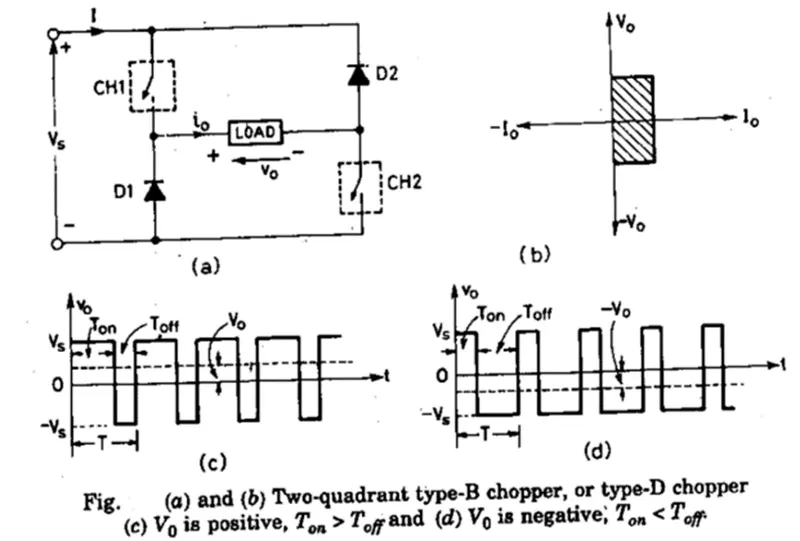
Two-quadrant type-b or Type-D Chopper is shown in the figure. When both the chopper CH1 and CH2 are at ON condition then the output average voltage Vo=Vs. When both the chopper is turned OFF but diodes D1 and D2 conduct, then the output voltage Vo=-Vs. The average output voltage is positive when the chopper turn-on time (Ton) is more than their turned-off (Toff) time i.e., Ton>Toff. Similarly, the average output voltage will be negative when the chopper turn-on time (Ton) is less than their turned-off (Toff) time i.e., Ton<Toff.
The direction of the flow of load current will always remain positive because chopper and diodes can conduct only in the direction as shown in the figure. As the output voltage Vo is reversible, therefore the power flow is also reversible. The operation of this type of chopper characteristic is represented by a hatched area in the first quadrant and fourth quadrant shown in the plots.
MATLAB Model:
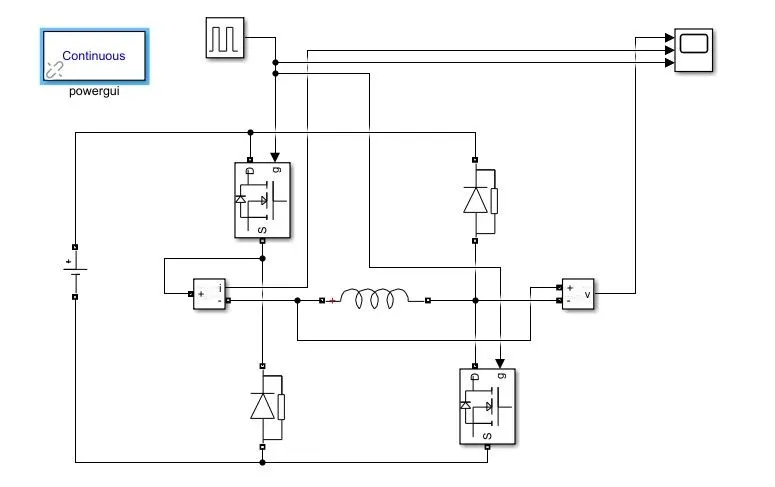
Model Explanation:
- Select the blocks of the MOSFET, diode, Inductor(load), pulse generator, dc supply, voltage & current measurement, and scope.
- Made the connections as per the above circuit diagram.
- Considered the Vs=24V, E=12V, Pulse amplitude as 10 with 50% duty cycle.
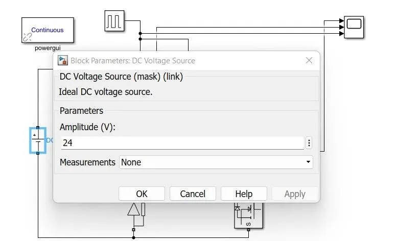
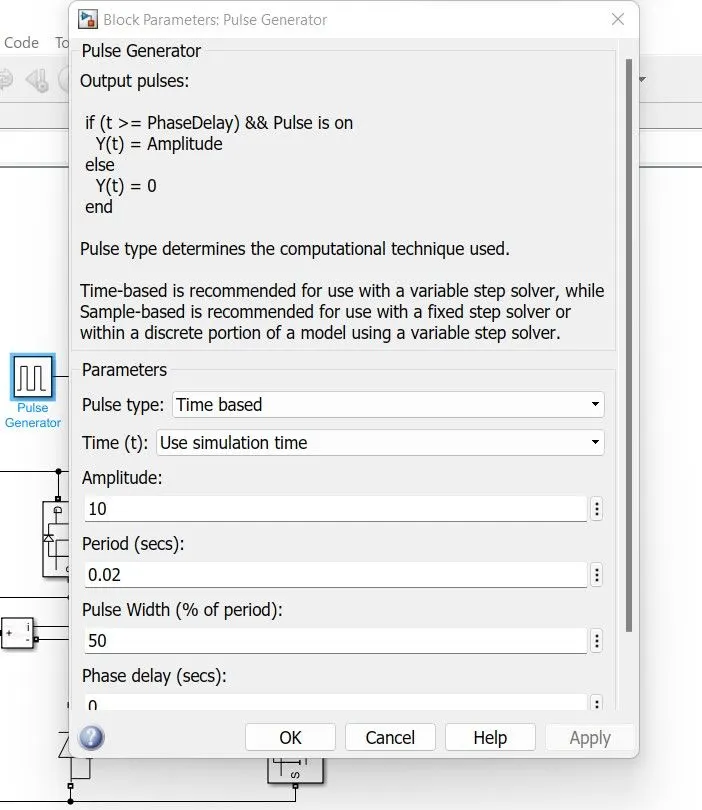
4. Run the simulation for the time period of 0.1 sec. Simulation results show below.
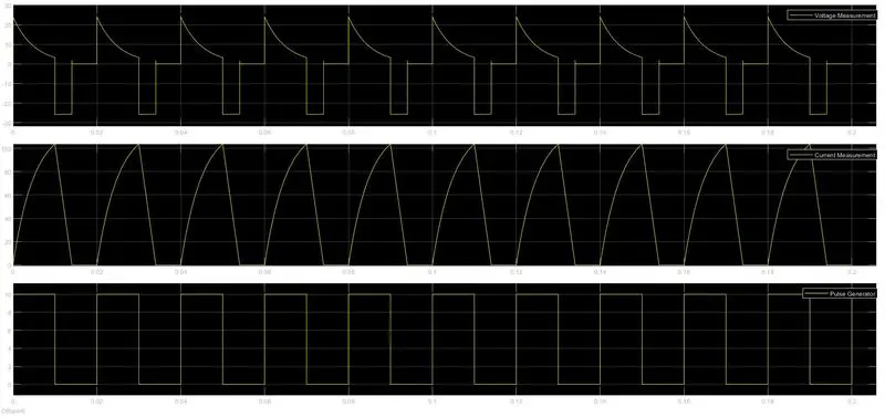
Here we can see that the voltage across the load inductor was plotted in both positive direction and negative direction. the load current was plotted in positive directions. In the operation of this 2-quadrant chopper, the Current is positive, and the Voltage is both positive and negative.
- Explain in a brief the operation of the BLDC motor.
The Brushless DC Motor:
Construction of BLDC Motor:
BLDC motors can be constructed in different physical configurations. Depending on the stator windings, these can be configured as single-phase, two-phase, or three-phase motors. However, three-phase BLDC motors with permanent magnet rotors are most commonly used.
Stator:
The stator of a BLDC motor is made up of stacked steel laminations to carry the windings. These windings are placed in slots that are axially cut along the inner periphery of the stator. These windings can be arranged in either star or delta. However, most BLDC motors have a three-phase star-connected stator. The stator must be chosen with the correct rating of the voltage depending on the power supply capability.
Each winding is constructed with numerous interconnected coils, where one or more coils are placed in each slot. In order to form an even number of poles, each of these windings is distributed over the stator periphery.
Rotor:
BLDC motor incorporates a permanent magnet in the rotor. The number of poles in the rotor can vary from 2 to 8 pole pairs with alternate south and north poles depending on the application requirement. In order to achieve maximum torque in the motor, the flux density of the material should be high. A proper magnetic material for the rotor is needed to produce the required magnetic field density.
Hall Sensors:
The Hall sensor provides the information to synchronize stator armature excitation with rotor position. Since the commutation of the BLDC motor is controlled electronically, the stator windings should be energized in sequence in order to rotate the motor. Before energizing a particular stator winding, acknowledgment of the rotor position is necessary. So, the Hall Effect sensor embedded in the stator senses the rotor position.
Most BLDC motors incorporate three Hall sensors which are embedded into the stator. Each sensor generates Low and High signals whenever the rotor poles pass near it. The exact commutation sequence to the stator winding can be determined based on the combination of these three sensors’ responses.
Working:
The brushless DC (BLDC) motor is really an AC motor! The current through it alternates, as we will see. It is called a ‘brushless DC motor’ because the alternating current must be variable frequency and so derived from a DC supply, and because its speed/torque characteristics are very similar to the ordinary ‘with brushes’ DC motor. As a result of ‘BLDC’ being not an entirely satisfactory name, it is also known as a ‘self-synchronous AC motor’, ‘variable frequency synchronous motor’, a ‘permanent magnet synchronous motor, and an ‘electronically commutated motor’ (ECM).
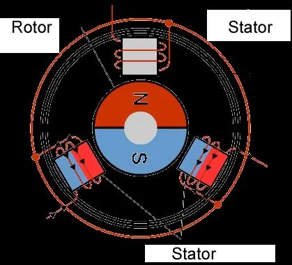
The basis of operation of the BLDC motor is shown in the above figure.
The rotor consists of a permanent magnet. In the above figure, the current flows in the direction that magnetizes the stator so that the rotor is turned clockwise, as shown and the rotor passes between the poles of the stator, and the stator current is switched off. Momentum carries the rotor on, and the stator coil is re-energized, but the current and hence the magnetic field are reversed. So, the rotor is pulled round in a clockwise direction. The process continues, with the current in the stator coil alternating. Obviously, the switching of the current must be synchronized with the position of the rotor. This is done using sensors. These are often Hall effect sensors that use the magnetism of the rotor to sense its position, but optical sensors are also used.
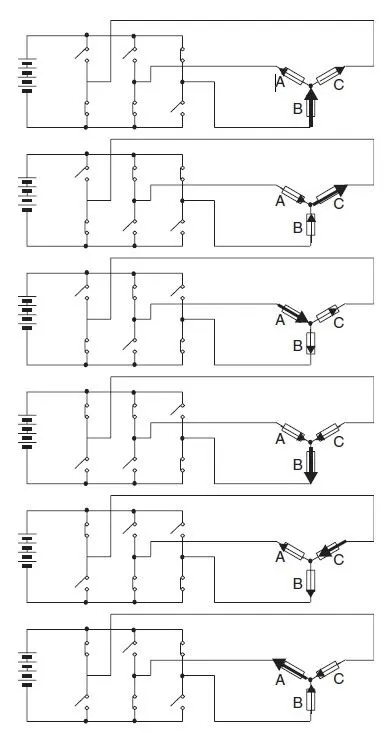
The switching of the current to generate a three-phase alternating current as shown below the figure in detailed
Advantages of BLDC Motors:
- Ability to work at higher speed and produce constant torque
- Durability
- The efficiency is almost 85-90%
- Ability to respond to the control mechanisms at high speeds
- No sparks and less noise, as the brushes are absent
- Ease of Motor Control (using BLDC motor controller solutions)
- Ability to self-start.
- Gets cooled by conduction and requires no additional cooling mechanism.
Applications of Brushless DC motor:
- Computer hard drives and DVD/CD players.
- Electric vehicles, hybrid vehicles, and electric bicycles.
- Industrial robots, CNC machine tools, and belt-driven driven systems.
- Washing machines, compressors, and dryers.
- Fans, pumps, and blowers.
Limitations of Brushless DC motor:
- BLDC motors cannot compete with conventional motors in the large power range (power output thousands of KW) or even in the medium power range (power output hundreds of KW).
- The cost and reliability of electronic controllers often become a limitation when BLDC motors have to replace established motors like capacitor-run motors.
- Construction of high-rating BLDC is not economical due to the cost of the permanent magnet is expensive.
- It has harmonic content in the back emf hence, some torque ripple will occur at motor torque.
- Demagnetization possibility also limits the input current in the BLDC
- A permanent magnet has less flux density compared to an electromagnet.