Week-6 Challenge: EV Drivetrain
Q1.
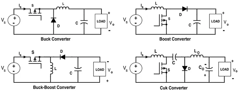
Power converters, such as rectifiers, buck converters, bidirectional DC-DC converters, and inverters are discussed with their uniqueness in HEV and PHEV.
E.g.: - EV and PHEV Battery chargers, including conductive chargers, inductive chargers, wireless chargers, and bidirectional chargers.
Rectifier: A rectifier is an electrical device that converts alternating current (AC), which periodically reverses direction, to direct current (DC), which flows in only one direction.
Rectifiers are mainly classified into two types:
- Uncontrolled Rectifier.
- Controlled Rectifier.
Uncontrolled Rectifier:
Uncontrolled rectifiers can be classified as follows:
- Bridge rectifier.
- Half wave rectifier
- Full wave rectifier
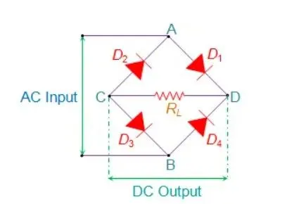
Bridge Rectifier: Bridge Rectifiers are circuits that convert alternating current (AC) into direct current (DC) using diodes arranged in the bridge circuit configuration. Bridge rectifiers typically comprise four or more diodes. The output wave generated is of the same polarity irrespective of the polarity at the input.
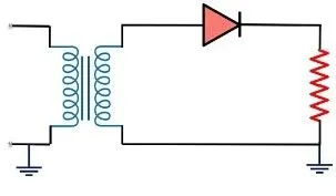
Half-wave rectifier: A half-wave rectifier converts an AC signal to DC by passing either the negative or positive half-cycle of the waveform and blocking the other. Half-wave rectifiers can be easily constructed using only one diode. The rectification efficiency of a half-wave rectifier is about 40.5%.
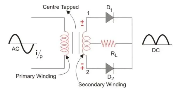
Full-wave rectifier: A full-wave rectifier is defined as a rectifier that converts the complete cycle of alternating current into pulsating DC. The rectification efficiency of full-wave rectifiers is 81.2%.
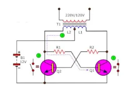
Inverter: A inverter is an electrical device that converts direct current (DC) to alternating current (AC). Power inverters have numerous applications in the power electronics field. It is used in various applications like induction heating, UPS, controlling electric motors, refrigerators, solar, and many more.
DC-DC converters: DC-DC converters are also referred to as linear or switching regulators, depending on the method used for conversion. DC-DC Converter line-up consists of a variety of products. This is a simple universal DC / DC converter (circuit, which converts DC voltage to another DC voltage). The input voltage can be about 9 - 18 V and the output voltage can be selected as needed in the range of about 3 - 50V. The output voltage can be both lower or higher than the input. It is suitable for a wide range of purposes, such as powering equipment (laptops, amplifiers, portable televisions, 5V USB appliances, 24V appliances ...) from the onboard network of 12V car battery or solar cell, battery charging from solar cells, and so on.
Given data
Vin=72V; Ia=400A; Ra=0.5ohm; K=0.7V-s; f(Ch)=400Hz
The vehicle speed-torque characteristics are given as Tv=24.7+(0.0051) w2 ------(1)
Steady state speed if duty cycle is 70% =0.7
Average Voltage (Va)=Vin*d =72*0.7 =50.4V
Torque equation T=((Va*K)/Ra) – ((K2*w)/Ra)
After substituting the values
T= ((50.4*0.7)/0.5) -((0.72*w)/0.5
T=70.56-0.98w-------(2)
By comparing of (1) & (2)
24.7+(0.0051) w2 = 70.56-0.98w
After simplification we get
0.0051 w2+0.098w-45.86=0(from quadratic equation ax2+bx+c=0 the x = [-b ± √ (b2 - 4ac)]/2a)
Therefore w= [-(0.98) ± √ ((0.98)2 – 4(0.0051) *(-45.86))]/2*(0.0051)
w = (-0.98±1.372)/0.0102
w= 38.92 rad/sec
w=-231.07 rad/sec
We get two values of ‘w’ angular speed, we will consider the positive value by assuming that motor is running CW direction.
Therefore, EV steady-state speed if the duty cycle is 70% =38.92 rad/sec.
Q3.
Mathematical model of a DC Motor for the below equation using Simulink.
ω= V/Kϕ –(Ra/Kϕ^2 )T
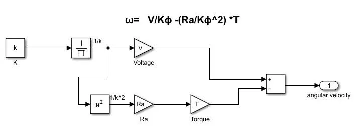
Simulink model file attached.
Q4.
From the given blog author made the comparison between DC brushless motor and AC Induction motor on basis of construction, working, performance, efficiency points, and Compatibility for the HEV, PHEV, and Pure EV applications.
The comparisons were as below
|
DC Brushless Motor |
AC Induction Motor |
|
The rotor consists of two or more permanent magnets that generate the DC magnetic field. |
The induction rotor has no magnets, just stacked steel laminations with buried peripheral conductors that form a “shorted structure.” |
|
The Magnetic field enters the stator core and interacts with the current flowing within the windings to produce the torque interaction between rotor and stator. |
Currents flowing in the stator windings produce a rotating magnetic field that enters the rotor. In turn, the frequency of this magnetic field as “seen” by the rotor is equal to the difference between the applied electrical frequency and the rotational “frequency” of the rotor itself. |
|
As the rotor rotates, it is necessary that the magnitude and polarity of the stator currents be continuously varied – and in just the right way - such that the torque remains constant and the conversion of electrical to mechanical energy is optimally efficient. The device that provides this current control is called an inverter. |
3-phase induction motor is connected to utility type 3-phase power, torque is produced at the outset; the motor has the ability to start under load. No inverter is needed. |
|
Brushless DC motor produces no starting torque when directly connected to fixed frequency utility power. They really need the aid of an inverter whose “phase” is maintained in step with the angular position of the rotor. |
Induction motors are directly compatible with conventional utility power |
|
Less rotor heat is generated with the DC brushless drive. Rotor cooling is easier |
Rotor cooling is not easier compared to DC drive. |
|
The DC brushless drive can also operate at a unity power factor and peak point efficiency is generally higher for this drive. |
The best power factor for the induction drive is about 85 percent. This means the peak point efficiency was a little low percentage than DC drive. |
|
In an ideal brushless drive, the strength of the magnetic field produced by the permanent magnets would be adjustable. |
Induction machines have no magnets and B fields are “adjustable,” since B is proportionate to V/f (voltage to frequency). |
|
When torque levels are low, the B field should be reduced such that eddy and hysteresis losses due to B are also reduced. Ideally, B should be adjusted such that the sum of the eddy, hysteresis, and I² losses is minimized. Unfortunately, there is no easy way of changing B with permanent magnets. |
The induction machine when operated with a smart inverter has an advantage over a DC brushless machine – magnetic and conduction losses can be traded such that efficiency is optimized. This advantage becomes increasingly important as performance is increased. |
|
DC brushless, as machine size grows, the magnetic losses increase proportionately and part load efficiency drops. |
In induction, as machine size grows, losses do not necessarily grow. Thus, induction drives may be the favoured approach where high-performance is desired |
|
Permanent magnet (PM) rotors are expensive and also difficult to handle due to very large forces that come into play when anything ferromagnetic gets close to them. |
Induction motors will likely retain a cost advantage over PM machines. Also, due to the field weakening capabilities of induction machines, inverter ratings and costs appear to be lower. |
|
The control of torque-speed range and over temperature is achievable in DC brushless drive. |
Induction machines are more difficult to control to achieve stability over the entire torque-speed range and over temperature |