Introduction to REVIT concepts
INTRODUCTION TO REVIT CONCEPTS
AIM:
To learn basic concepts and tools of REVIT Software
INTRODUCTION:
Autodesk Revit is a building information modeling software for architects, structural engineers, mechanical engineers, electrical engineers, and plumbing (MEP) engineers, designers, and contractors. This software is user friendly and used to make 3D design, analysis, optimization, and real visualization
Building Information Modeling (BIM) has become an essential part of any design project by facilitating smarter, faster, stronger designs that make economic sense while reducing environmental impact. BIM provides support every step of the way from design and visualization, to simulation and construction
Benefits of REVIT:
The software helps teams to collaborate, innovate, and connect with clients in more productive ways
1. Parametric Components
2. Collaborative Tools
3. Realtime 3D modeling software
4. Project Scheduling
5. Sustainability and Optimization
Revit in various disciplines:
In Revit, each view has a discipline assigned to it, this controls what elements are visible and which are hidden.
For example, in an architectural view, we can see walls, windows, and doors but we might not be able to see structural elements such as beams and trusses or mechanical elements such as ducts.
1. Architectural design - To Visualize the project with different design solutions
2. Structural engineering - To model 3D reinforcement designs and conduct structural analysis
3. MEP engineering - It provides mechanical, electrical, and plumbing (MEP) engineers with tools to design complex building systems and analyze the performance
4. Construction - It helps to minimize the constructability risks and documentation of the project
1. From the File menu, create a new project (Structural/Architectural/Construction template) and name the project appropriately
AIM:
To Create a new project and name the project appropriately
PROCEDURE:
Step 1:
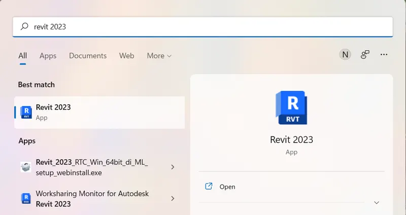
1. Click on the Windows button and Type Revit to Open Revit software
Step 2:
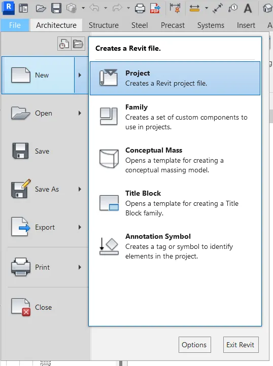
1. Once the Revit is opened, click on the File tab
2. In the file tab, Select New > Project and open the new project
Step 3:
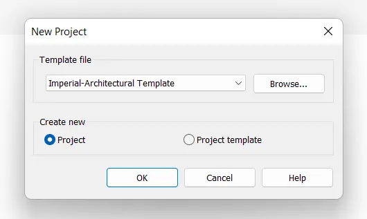
1. In the New Project dialog box, select the template file as Imperial- Architectural Template
2. Select Create new as Project option and open the project
RESULT:
The new project has been created with Imperial- Architectural Template File.
2. Save the new project file. Close and open using icons from the file toolbar
AIM:
To Save the new project file, close and open using icons from the file toolbar
PROCEDURE:
Step 1:
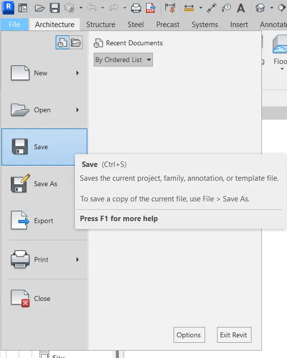
1. Save the new project file by clicking the save button in the File tab ( File > Save > Choose the folder that you want to save )
2. Give the New Project name as Introduction to Revit concepts
Step 2:
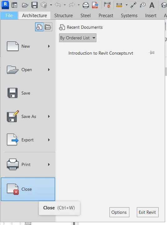
1. Close the file by clicking the close button in the File tab
Step 3:
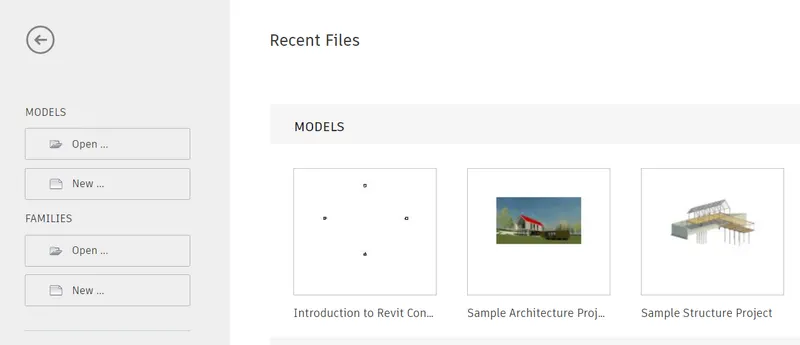
1. Open the Drawing file in the Recent files Section using the file toolbar
RESULT:
The project has been saved, closed, and opened using Icons from the File Toolbar.
3. From the architecture/ Structure toolbar familiarize yourself with options to draw a wall. Create a rectangular layout of walls of about 40'-0" x 35'-0"
AIM:
To create a rectangular layout of walls of about 40'-0" x 35'-0"
PROCEDURE:
Step 1:
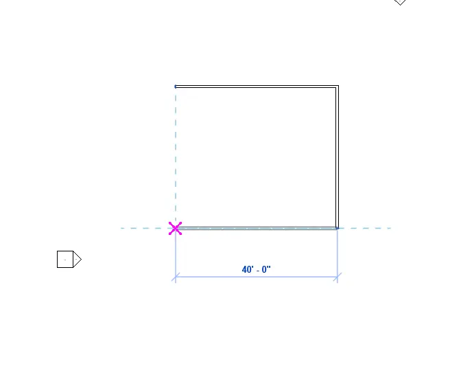
1. In the new project, Set the units by typing UN
2. Click on the Architectural tab and select the Wall tool
3. After Selecting the wall tool, now select the line option to draw the walls
4. Click on the screen and move the cursor towards the right and give the distance as 40'
5. Next move the cursor downwards and give a distance of 35'
Step 2:
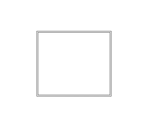
1. Next continue to move the cursor towards the left and give the distance as 40'
2. Close the wall by clicking on the starting point
RESULT:
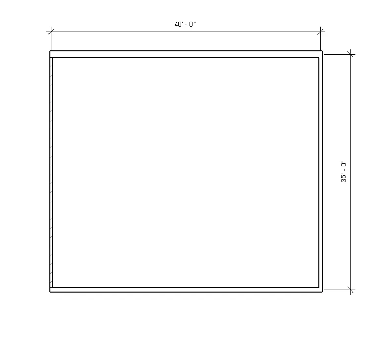
The Rectangular Wall layout has been drafted with the dimension of 40' x 35'.
4. From the Annotate toolbar, use the aligned option to add dimensions to the layout
AIM:
To add dimensions to the wall using the aligned dimension option
PROCEDURE:
Step 1:
1. Click on annotate tab and select the aligned dimension option
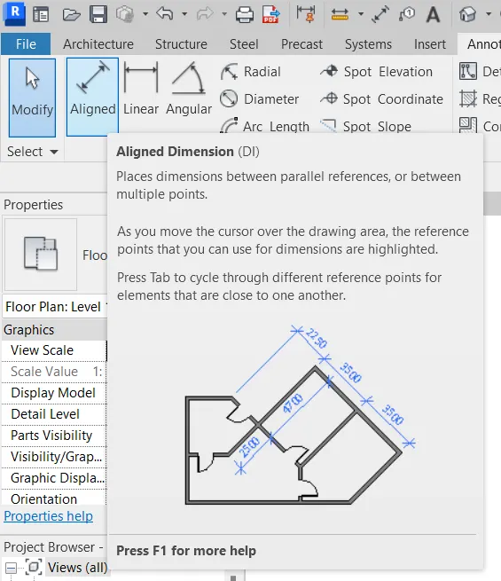
Step 2:
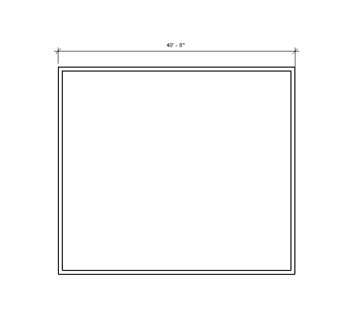
1. Select the first point of the dimension and the second point of the dimension
2. Place the dimension on the screen anywhere as shown in the figure below
Step 3:
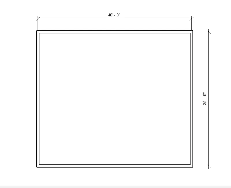
1. Repeat the aligned dimension and give dimensions horizontally and vertically as shown in the figure below
RESULT:
The Drafted Wall layout has been dimensioned using aligned dimension in Annotate tab.
5. Use the properties browser to switch different wall types
AIM:
To create different wall types using the Properties browser
PROCEDURE:
Step 1:
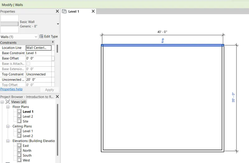
1. Open a new project and Select any side of the wall
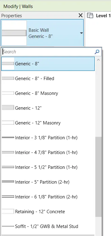
2. Fo to properties browser and select the wall type as Basic Wall generic 12"
Step 2:
1. Select different types of walls and assign them through the wall
RESULT:
The walls have been switched into different types of wall types using the property browser.
6. Create a 3D view from the view toolbar and save the view with the appropriate name
AIM:
To create a 3D view of the wall and save the view with the appropriate name
PROCEDURE:
Step 1:
1. Open the project that we created earlier
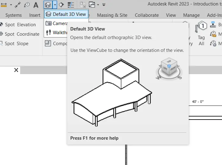
2. Click on the view tab and select Default 3D View
Step 2:
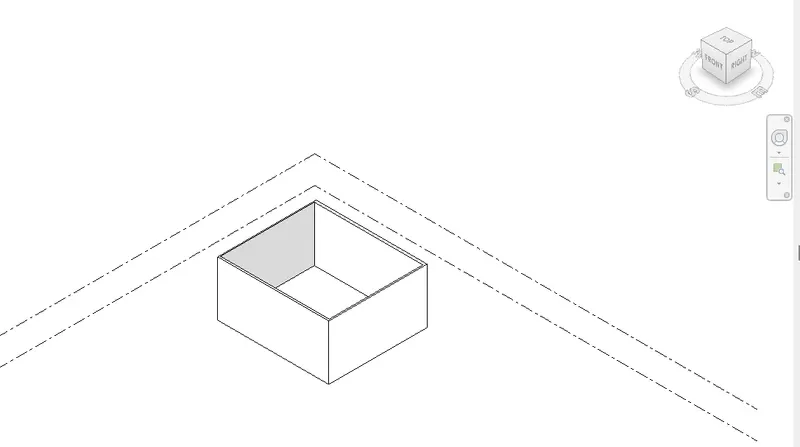
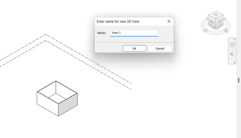
1. It will convert the project into a 3D view as shown in the figure below
2. Select the view that you want to save
Step 3:
1. Enter a name for the new 3D view as View 1 and save it
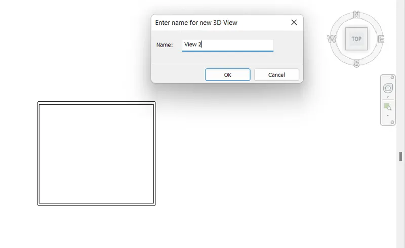
2. Similarly give the name for the new 3D view as View 2 and save it
RESULT:
The 3D view has been created and saved with the names View 1 and View 2.
7. Navigate through the 3D model using the view cube. Orbit/pan through the model layout created
AIM:
To navigate through the 3D model using the view cube
PROCEDURE:
Step 1:
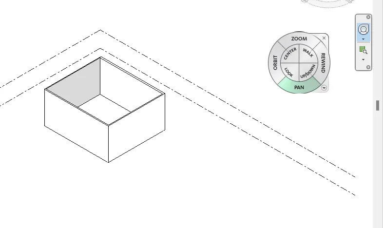
1. Click on the view tab and select the user interface option
2. Select the navigation bar
Step 2:
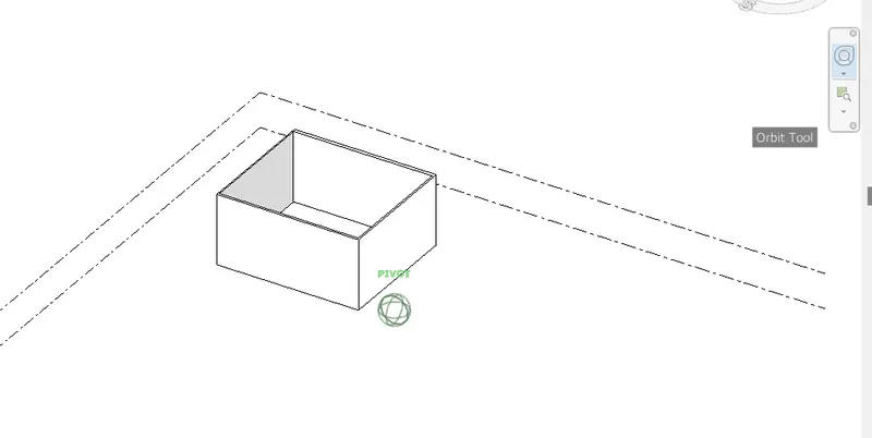
1. Select the Orbit tool and move the wall in different directions
Step 3:
1. Select the pan tool and move the cursor through the model space
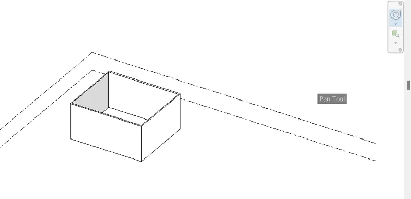
RESULT:
The model space has been navigated using orbit and pan mode.
8. Use the visibility settings option below to switch models to shaded, realistic, hidden lines options
AIM:
To Switch model space to different visible settings
PROCEDURE:
Step 1:
1. Open the project file that we created earlier
2. Click on Visual styles present at the bottom of the screen
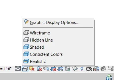
3. Switch between the styles ( i.e., wireframe, hidden line, shaded, consistent colors, realistic )
- Wireframe
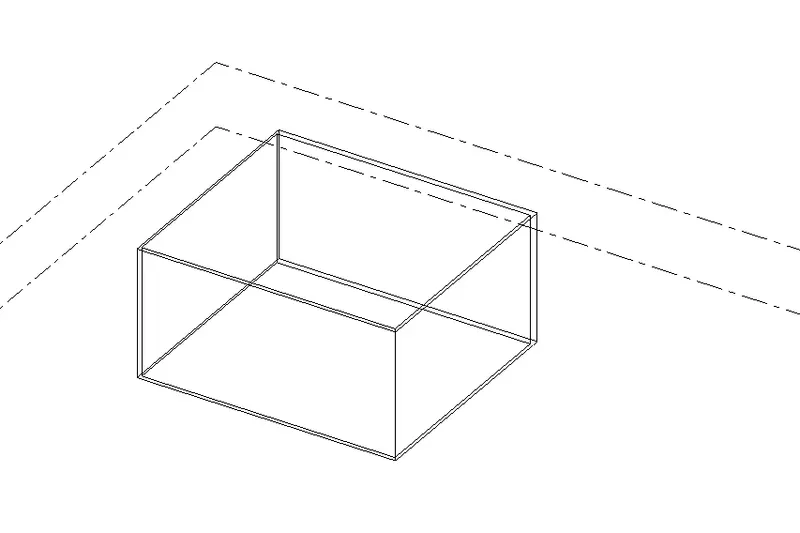
- Hidden line
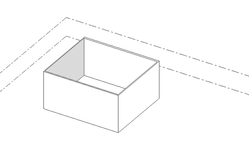
- Shaded
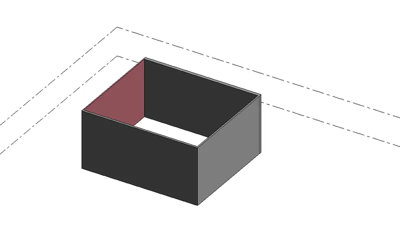
- Consistent Colours
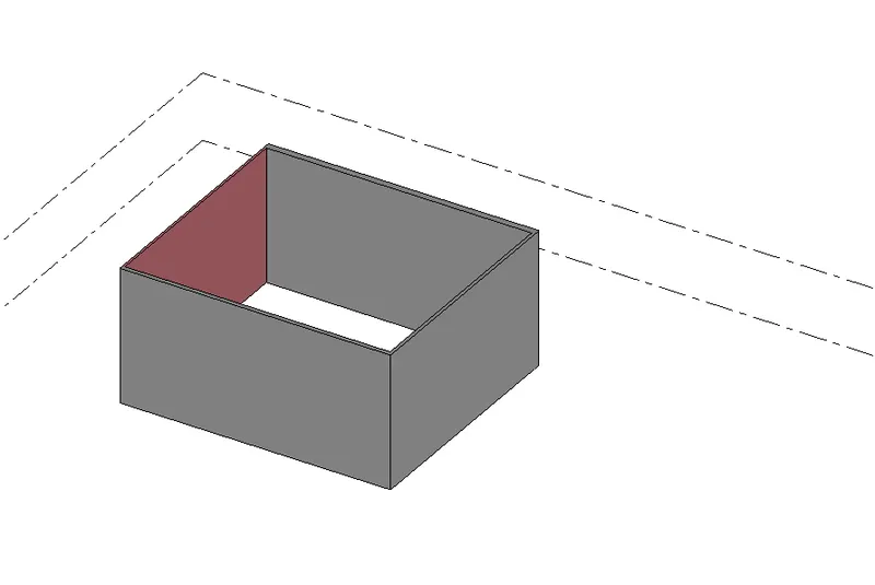
- Realistic
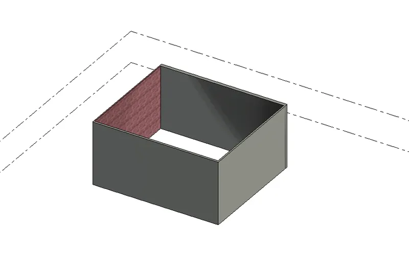
RESULT:
The model space has been switched to different visible settings.
9. Turn the sun path on and off to view shadings in the layout created
AIM:
To turn the sun path on and off to view shadings in the layout
PROCEDURE:
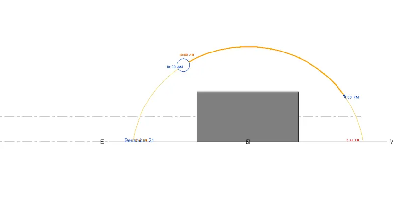
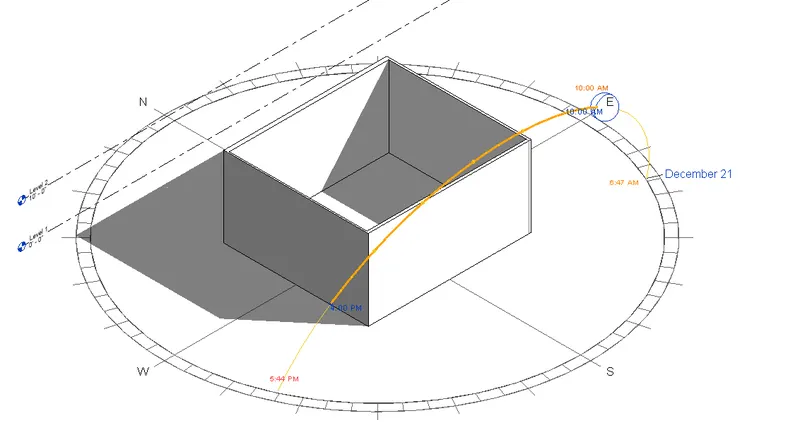
Step 1:
1. Open the new project that we created earlier
2. Click on the Sun path Symbol present below the bottom of the screen
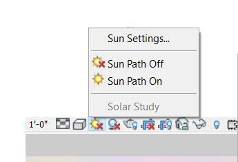
Step 2:
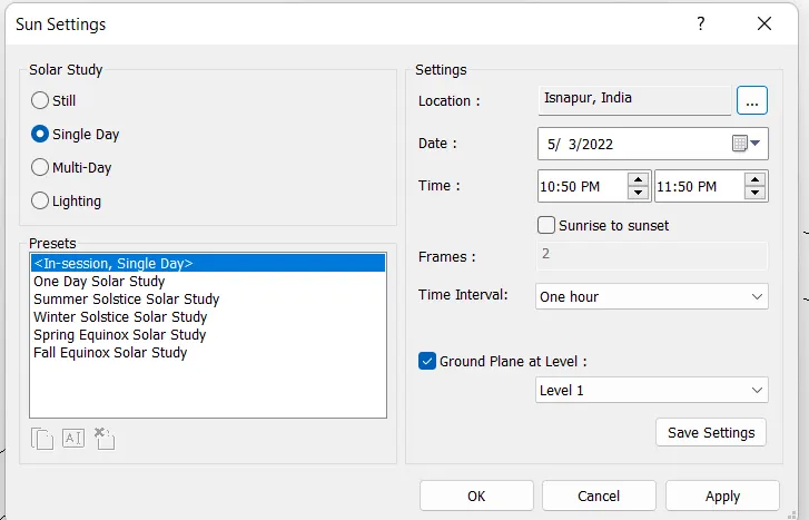
1. Go to sunset settings and select solar study as a single day
2. Select location, date, and time and press Ok to apply settings
Step 3:
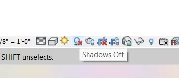
1. Turn on the sunset option in the bottom toolbar
2. Turn the shadows beside the sunset option
Step 4:
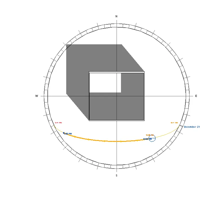
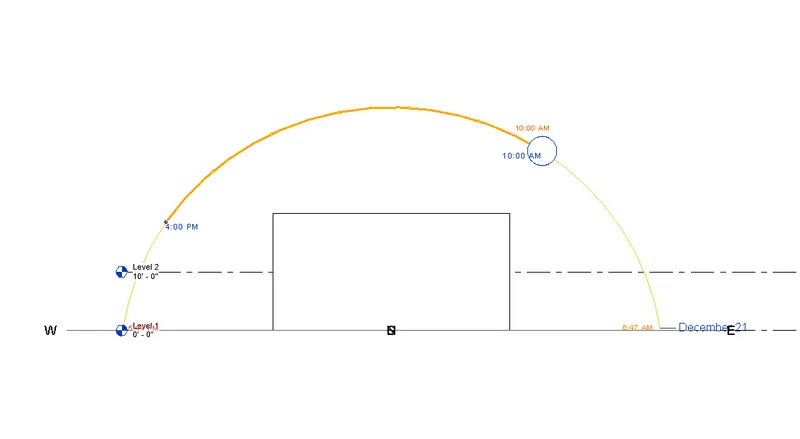
1. Switch between the views to see the shades
- Top View
- Front View
- Back View
- Adjustable View
RESULT:
By using the Sun path option, all the shades of different views have been created.
10. Use the manage toolbar to enter project settings, choose project name and project issue date according to the convenience
AIM:
To create the project name and project issue date using the manage toolbar
PROCEDURE:
Step 1:
1. Open the project that we created earlier
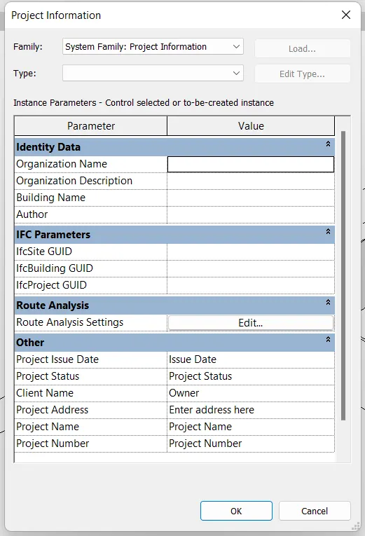
2. Click on the manage toolbar and select the project information option
Step 2:
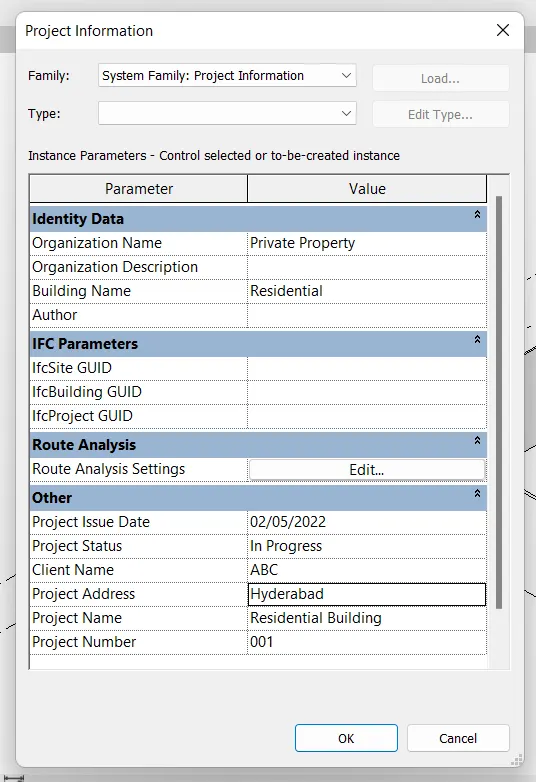
1. Give the necessary details such as organization name, building name
2. Type project issue date as of 02/05/2022 and project status as In progress
3. Type Client name as ABC, Project Address as Hyderabad, Project name as Residential building, and Project number as 001
RESULT:
All the project information is created
11) What is the Analyze toolbar used in Revit? How it is beneficial to design and modeling?

Analyze toolbar used in Revit and beneficial for design and modeling. Analyze toolbar helps us to perform analysis on our structural building by applying different load combinations. The boundary conditions enable us to define point line and area boundary conditions in an analytical model.
Energy and daylighting analysis with Insight software allow designers to analyze the performance of their designs, leading to more efficient buildings and sustainable practices. Energy simulation can help you analyze the movement of energy in, out, and through the rooms and volumes in a building model. This information can help designers make better informed, cost-effective decisions that improve the performance and reduce the environmental impact of buildings.
12) What are the links that Revit supports to be linked to the model?

Linking models are primarily intended for linking separate buildings, such as those that compose a campus. You can link architectural models, structural models, and MEP models. You can link Revit LT models to other Revit LT models. You can also link Revit models to Revit LT models. Revit opens the linked model and keeps it in memory when you link a model into a project RevitRevit opens the linked model and keeps it in memory. The more links a project contains, the longer it can take to open. Linked models are listed in the Revit Links branch of the Project Browser. You can convert linked Revit models to groups, and you can convert groups to linked Revit models.
Link Revit: Linking another Revit model to the current model

Collaboration tool offers users such as structural engineers and MEP engineers to work simultaneously. It enables cloud files and Collaborates with multiple instances of independent files. It creates a complete building model by bringing different models together
Revit provides several different ways to collaborate with team members who are also using the software. You can link multiple Revit models together, allowing team members to work in context. Through work sharing, users on the same local area network (LAN) can work together in the same Revit model.