Structural analysis of a buidling using Robot Structural Analysis
Structural analysis of a building using Robot Structural Analysis
1) What are HVAC systems? Why are they essential in the modeling of buildings
Answer:
HVAC stands for heating, ventilation, and air conditioning systems. This system is responsible for heating and cooling your home and includes products like furnaces, air conditioners, heat pumps, ductwork, thermostats, and other home comfort controls.
An HVAC system combines the processes of heating, cooling, and air ventilation using a thermostat and other devices. Thus, doing so enables the proper circulation of air inside the building. It also helps in modifying the building temperature according to the needs of the climate or season.
Essentials of HVAC:
1. HVAC systems control the overall climate in the building. They also make the proper adjustments whenever we experience changes in outdoor temperature.
2. HVAC systems are used for controlling the overall climate in a building. This means that when it’s warm outside, it balances the temperature to make the inside cooler or warmer during the cold season.
3. The air conditioner works during the warmer days while boilers or heaters are turned on during the colder days.
4. During the winter season, the HVAC systems (mainly the boilers or heaters) work to keep the indoor temperature at a comfortable level.
5. In hotter times of the season, the HVAC systems regulate air temperature by providing the necessary cooling to keep the entire building comfortable.
6. HVAC systems not only regulate the temperature inside the building but also improve the quality of air.
7. The quality of air pertains to humidity, and a typical HVAC system will reduce the amount of humidity in the air
8. HVAC systems help you achieve more savings when it comes to energy bills. Gone are the days when we used fans and old-school air conditioners to feel cooler inside a building or fireplaces to keep us warmer.
2) From the week 7 assignment, based on the building design use the same Revit file to design an HVAC system for each floor to cover the topics included in the class.
a. Typical HVAC unit includes a Distribution center
b. Collector
c. Ducts
d. Blower
Based on the layout choose appropriate ducts and elevation using the property browser and assign the components to appropriate groups to complete the modeling of the HVAC unit
AIM:
To design a HAVC System for each floor based on the building designed
INTRODUCTION:
HVAC stands for heating, ventilation, and air conditioning. It refers to the systems that regulate and move heated and cooled air throughout residential and commercial buildings, from homes to offices to indoor stadiums. Although there are many options when it comes to HVAC systems, they all work similarly, taking in the fresh air and using a mechanical ventilation system to heat or cool it to the desired temperature.
HVAC units also can control humidity levels and improve air quality through air cleaners that capture bacteria, spores, and virus-sized particles. The HVAC technician who comes to your home for a pre-installation evaluation will help you determine which system and options are best for you and your home.
PROCEDURE:
Step 1:
1. From the desktop, open the Revit software by clicking on the Revit icon
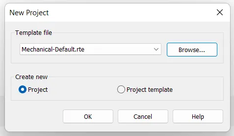
2. Then Click on New project to open the new project file
3. Select the Template file as Mechanical Default and press Ok
Step 2:
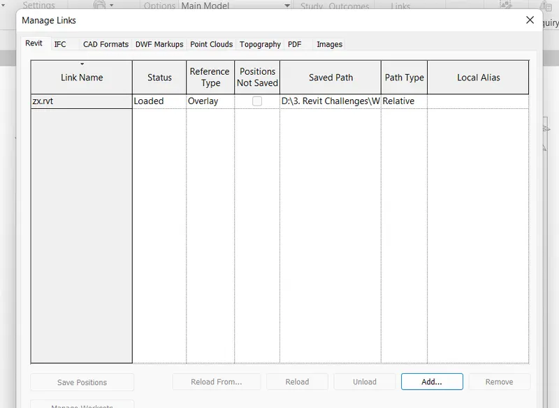
1. After opening the mechanical template, now we have to link the architectural file
2. Go to the Insert tab, and click on link Revit to link the architectural file into the mechanical template
3. Then manage the architectural file by clicking on manage links in the manage tab
Step 3:
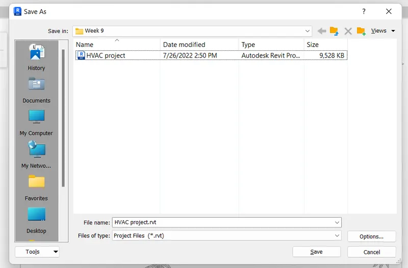
1. After Linking the architectural file, now we have to save the file with the HVAC System
2. Go to the File option, Click the save option and give the file name as HVAC project
Step 4:
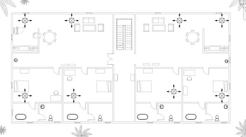
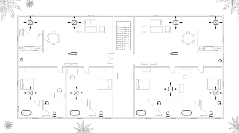
1. Now go to the System tab, and select the Air terminal tool
2. Select the Air terminal tool as a Supply diffuser from the Project browser
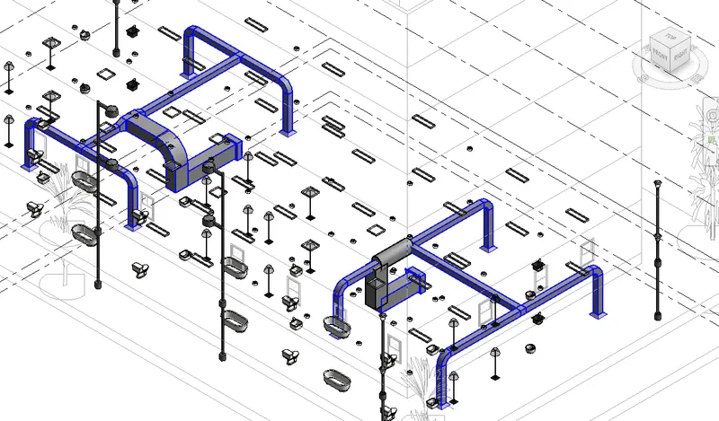
3. Place the Air Terminals in the required location as shown in the figure below
Step 5:
1. Now go to the system tab again, and select the mechanical properties option
2. In that tab, select the loaded family option to load the various mechanical systems
3. Select the Air handling unit from the libraries and load it into the Revit
4. Select the Air handling unit and place it in the desired location as shown in the figure below
Step 6:
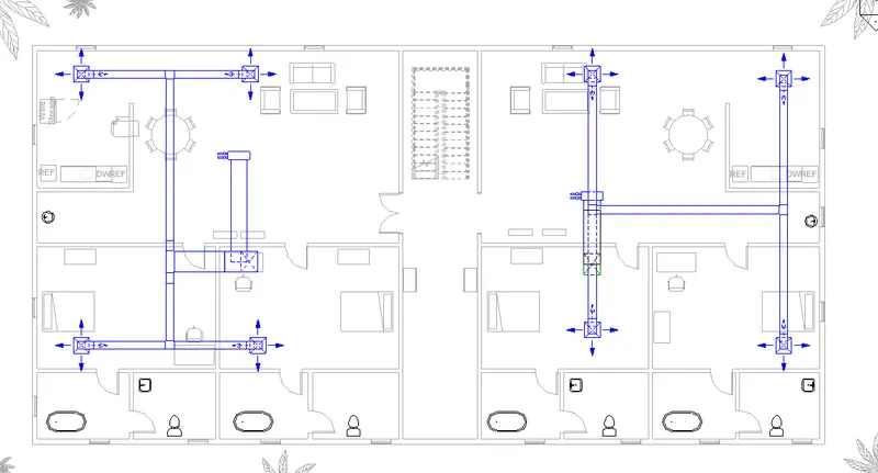
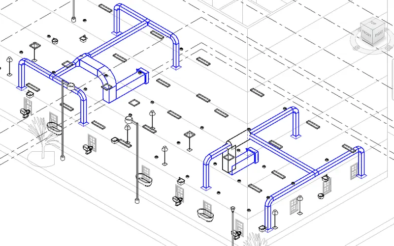
1. Now we need to make the duct layout for the components
2. Select all the mechanical components that we placed on the plan
3. After selecting the components, select the Duct tool in the ribbon tab
4. It will create the duct system and then press ok to create the connector
5. After creating the connector, click on Generate Layout in the ribbon tab
6. Select the layout from the various layouts options and click finish layout
Step 7:
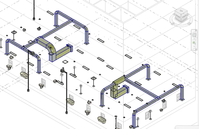
1. After creating the HVAC layout on the first floor, we have to copy it to the other floors
2. Select all the mechanical components and copy it
3. From the ribbon tab, select the paste option and paste it through the aligned levels as shown in the figure below
RESULT:
The HVAC system has been designed successfully for each floor of the architectural building.
3) Use the add-ins tab to load plug-ins for robot structural analysis to your Revit software
AIM:
To load plugins for robot structural analysis to Revit software using the add-ins tab
INTRODUCTION:
Robot Structural Analysis Professional is structural load analysis software that verifies code compliance and uses BIM-integrated workflows to exchange data with Revit. It can help you to create more resilient, constructible designs that are accurate, coordinated, and connected to BIM.
Autodesk Robot Structural Analysis hosts a range of powerful FEM solvers enabling structural engineers to conduct complex calculations such as modal, harmonic, spectral, dynamic, non-linear, footfall analysis, and many more.
This comprehensive structural engineering design software solution allows enhanced BIM operability both within the AEC collection and other software enabling engineers to iterate and optimize their designs with full communication between packages ultimately streamlining the design process and allowing traceability of design changes along the way.
PROCEDURE:
Step 1:
1. From the desktop, open the Revit software by clicking on the Revit icon
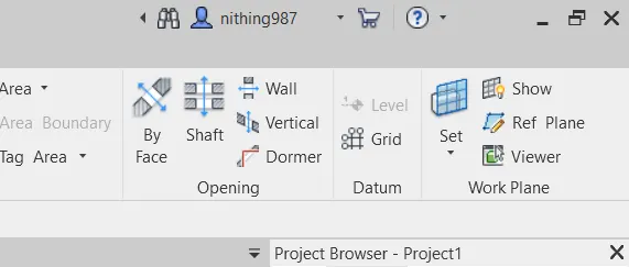
2. Now click on the Cart option as shown in the figure below
Step 2:
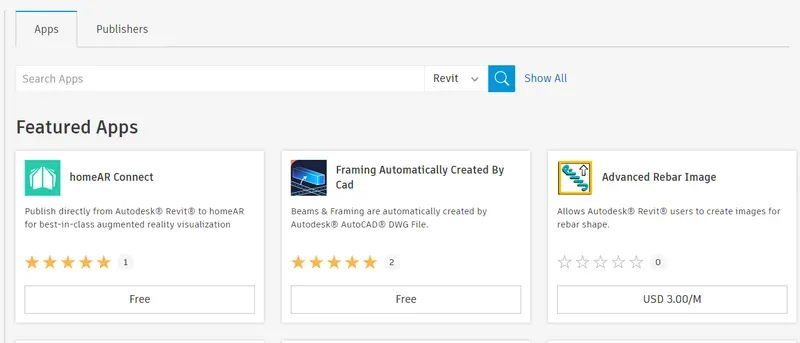
1. Click on the Autodesk app store in the Revit software
2. It will be redirected to the Autodesk app store website
Step 3:
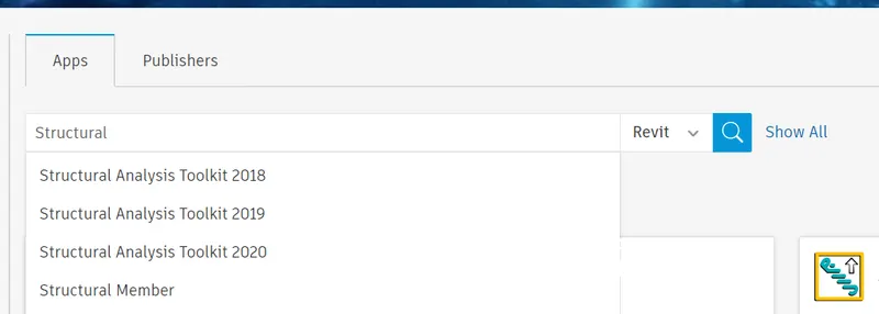
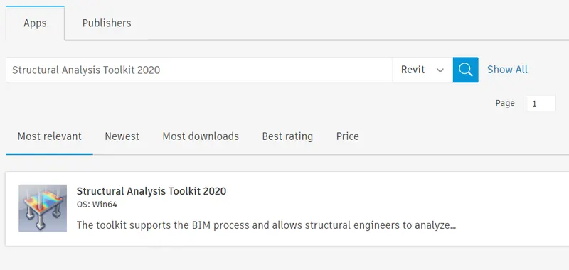
1. In the search toolbar, type structural analysis toolkit 2020
2. Then search it, it will show the results as shown in the figure below
Step 4:
1. Then download the Structural Analysis Toolkit from the Autodesk app store
2. After downloading the Structural Analysis toolkit, install it
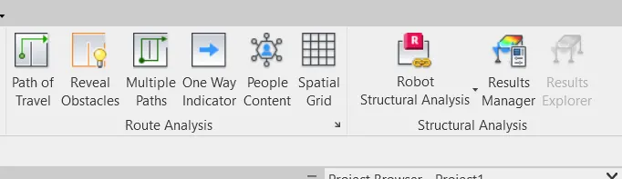
3. The software will be installed and appears in the Revit software under analyze tab
RESULT:
The robot structural analysis toolkit has been successfully loaded into the Revit software using the add-ins tab
4) Why do we need to assess buildings/analyze while modeling elements? Does design affect modeling in anyways?
Answer:
Structural design is undoubtedly the most important process in a building project, specifically for the accurate and timely development of a structural framework. This is a critical part of the project since the framework holds and transmits distinct kinds of loads and supports the architectural and MEP systems.
Structural design suitable for architect ideas is time-consuming and expensive when using traditional design methods. Each concept had to be examined and manually calculated often with help of simplified methods. Nowadays, BIM-3D models prepared by an architect can be relatively easily and quickly converted to the analytical model that engineers can use in the structural analysis
The structural analysis helps to determine the cause of a structural failure. The purpose of the structural analysis is to design a structure that has the proper strength, safety, and rigidity. It will then allow for the proportion of member and their detailing, and joints.
The analysis Model is a technical representation of the system. It acts as a link between system description and design model. In Analysis Modelling, information, behavior, and functions of the system are defined and translated into the architecture, component, and interface level design in the design modeling.
Objectives of Analysis Modelling:
- It must establish a way of creating software design.
- It must describe the requirements of the customer.
- It must define a set of requirements that can be validated, once the software is built.
Assessment of building analysis enables us to design the structure and structural rudiments accordingly like placing the columns, arrangement of trusses, shafts, etc. Designing a structure is most effective when the assessment of the structure is done. Modeling is surely affected by design.
As designing involves creating a plan of a model when design changes modeling varies. As design depends on the structural analysis of the model, both designing and modeling are affected by the assessment of the structure.
5) From the structural model developed in weeks 6 and 7, export the complete analytical model to robot structural analysis.
a. List your assumptions on what boundary conditions will be realistic for the analysis approach
b. Use the design standards to decide what loads must be applied to floorings based on the type of structure decided
c. List the load combinations and include them in the analysis model
d. Analyze the building and report the following results
i. Maximum Moment on each floor for all Load Combinations
ii. Maximum Displacement on each floor for all Load combinations
iii. Lateral Displacement in building for all Lateral Load combinations
e. After analysis, do you think you have a better approach or idea in modeling structural members?
AIM:
To export the complete analytical model to robot structural analysis from the structural model developed in weeks 6 and 7
INTRODUCTION:
The analytical model represents a simplified version of the structural descriptive Revit model. Coming together to create an engineering model, the analytical model contains information such as the structural components, the geometry of the structure, cross-section of the structural elements, end conditions, material properties, and loads.
A user has the option to activate the analytical representation of an element for such Revit components as a Structural Column, Structural Framing elements (such as beams and braces), Structural Floors, Structural Walls, and Structural Foundation elements.
The properties defining analytical element for any descriptive structural element have:
• Instance parameters
• Material properties
• A modifiable position; either relative to the descriptive structural members or concerning a projection plane (grids or reference planes)
• End conditions
PROCEDURE:
Step 1:
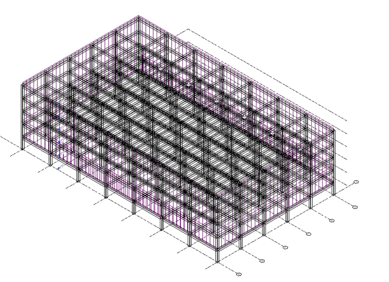
1. First Open the Structural model that we developed in weeks 6 and 7
2. Then go to analyze tab, to apply the various load cases and combinations
Step 2:
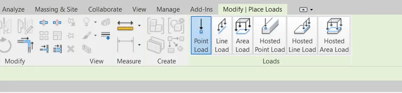
1. In the analyze tab, select the load's tool from it
2. Then select the Line load option from the loading tool
3. The modify tab will appear, select the rectangle tool and sketch the load boundary
4. Similarly apply the area load as shown in the figure below
Step 3:
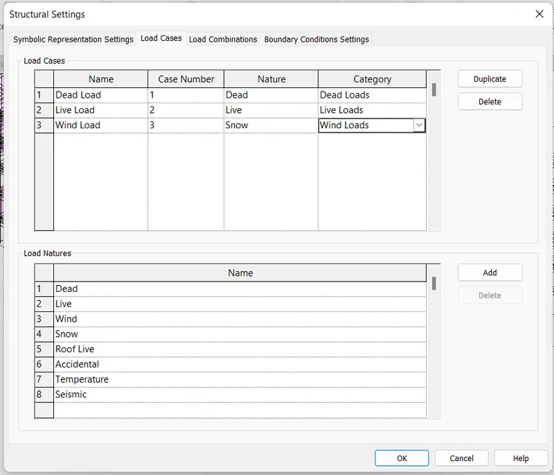
1. Now go to the analyze tab again, select the load cases option
2. Add the load cases such as Dead load, Live load, and Wind load
3. Give the nature of the load according to the condition and press ok
Step 4:
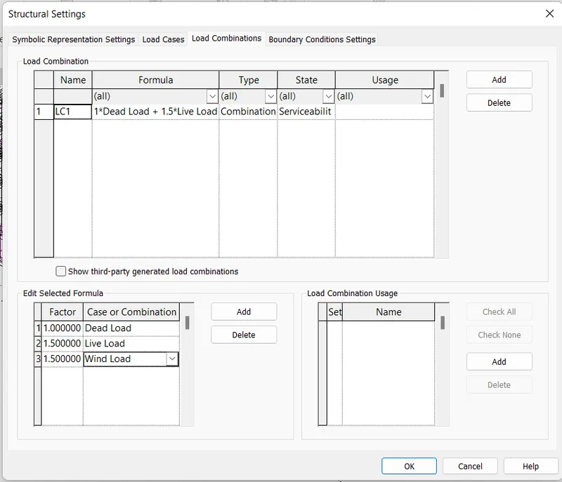
1. Go to analyze tab again and select the load combinations option
2. Add the new load combination using the add option
3. Select the load that we want to apply and give factor as a formula to it
4. Here, I'm selecting the load combinations as 1.0 DL + 1.5 LL + 1.5 WL
5. After assigning the load combinations in the dialog box, press okay
Step 5:
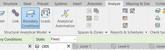
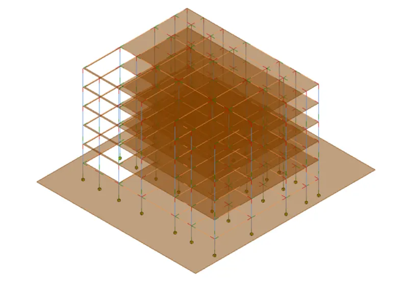
1. After assigning the load cases and load combinations, now we have to assign the boundary conditions to it.
2. Select the Boundary Conditions tool from the analyze tab
3. We have to apply the boundary conditions in an analytical view only
4. Select the boundary condition has to point and then apply the boundary conditions to all the columns
Step 6:
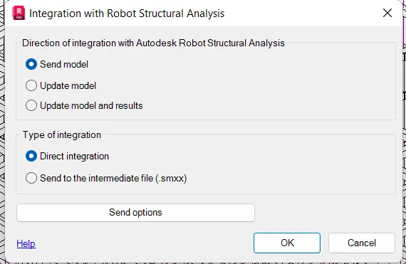
1. After assigning all the loads, load cases, load combinations, and boundary conditions now we have to export them into the robot structural analysis
2. Select the Robot Structural Analysis from the analyze tab
3. Then select the Robot Structural Analysis link and press okay to send the model
Step 7:
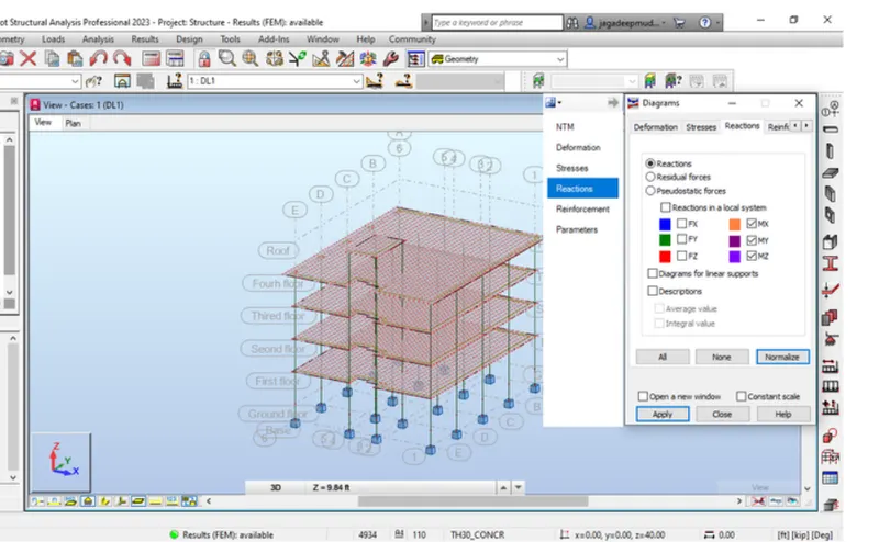
1. After sending the model to the robot structural analysis, now we have to see the calculation results
2. In the robot structural analysis, go to the results tab and select the diagrams from the member's option
3. It will show the Stress and reactions of Fx, Fy, and Fz values
Step 8:
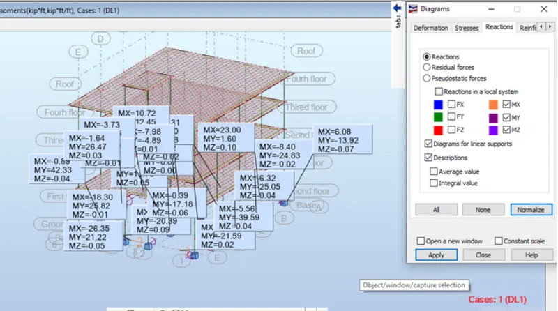
1. Select the reactions option from the diagrams tool
2. Now we can see the bending moment and shear force values i.e., MX, MY, and MZ values
RESULT:
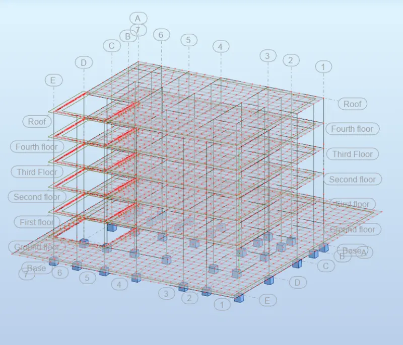
The Analytical model of the structural model that we developed in weeks 6 and 7 has been exported to the robot structural analysis successfully
6) What is energy analysis and why do we need to consider it while modeling in Revit?
How does the factor of sustainability improve the quality of your design?
Answer:
Energy analysis is the most common method for evaluating energy conversion systems. It is based on the first law of thermodynamics which is an expression of the conversion of energy. This analysis makes an energy balance for any energy conversion system and usage of the energy source while losses can be determined.
Energy analysis can be used to:
1. Determine the exergy efficiency of a system and compare it with alternative options.
2. Identify the contribution of components or subsystems to the overall exergy destruction.
Energy simulation can help you analyze the movement of energy in, out, and through the rooms and volumes in a building model. This information can help designers make better informed, cost-effective decisions that improve the performance and reduce the environmental impact of buildings.
The whole building energy simulation measures expected energy use (fuel and electricity) based on the building's geometry, climate, building type, envelope properties, and active systems (HVAC & Lighting). It takes into account the interdependencies of the building as a whole system.
The energy model created from the Revit building model can be displayed in Revit, so you can view and validate the energy model used for analysis. The energy model can also be exported to third-party applications for further analysis in a variety of common formats: gbXML, DOE2, and EnergyPlus.
Sustainable design seeks to reduce negative impacts on the environment, and the health and comfort of building occupants, thereby improving building performance. The basic objectives of sustainability are to reduce the consumption of non-renewable resources, minimize waste, and create healthy, productive environments.
Sustainable design principles include the ability to:
- optimize site potential;
- minimize non-renewable energy consumption;
- use environmentally preferable products;
- protect and conserve water;
- enhance indoor environmental quality; and
- optimize operational and maintenance practices.