Usage of Collaborate tool in REVIT
Usage of Collaborate tool in REVIT
1) Open an architectural template. Using the Manage tab set the project base point and project shared coordinates for the project
AIM:
To set the project base point and project shared coordinates for the architectural template using the manage tab
INTRODUCTION:
A Revit project has internal coordinates for all the elements that compose the model in a project. Those coordinates are known to this project only. This is sufficient if you have a standalone model whose position is not relevant to other models or a site. However, if you want the position of the model to be known to other linked models, you need to share coordinates.
Use the Shared Coordinate tools to establish the relative positions of the different files and ensure that those relationships are maintained. Use the Acquire Coordinates tool or the Publish Coordinates tool to establish a common coordinate position and then share that position between files.
PROCEDURE:
Step 1:
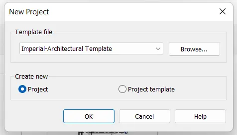
1. Open the Revit Software and click on the new project
2. Select the template file as an architectural template
Step 2:
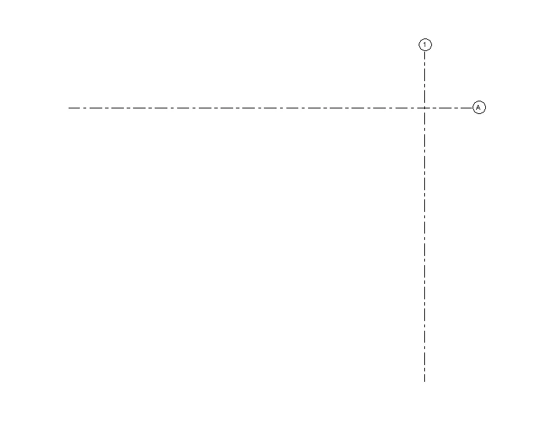
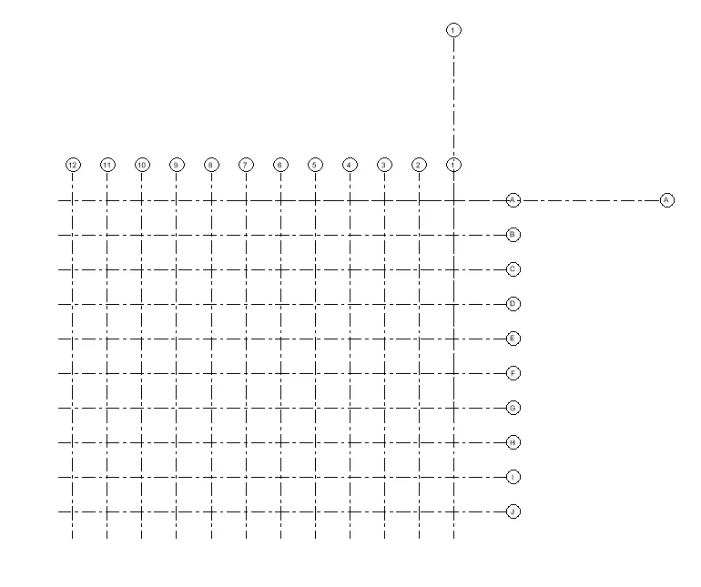
1. Now we have to draw the reference grids for the project base point
2. Select the grid tool from the architectural tab
3. Draw the horizontal and transverse grids as shown in the figure below
Step 3:
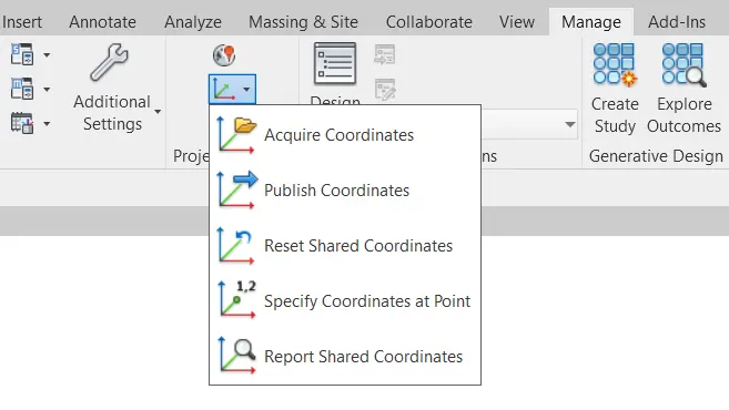
1. Now we have to specify the coordinates for the base point
2. Go to the Manage tab and select the project coordinates tool
3. In that section, select the specified coordinates at a point option
Step 4:
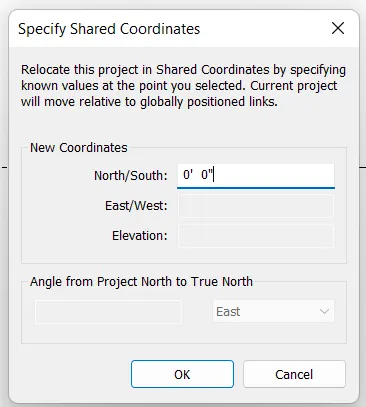
1. Select the base point as the intersection of horizontal and transverse grid lines
2. Specify the new coordinates as 0'0" for North/South and 0'0" for East/West
3. After providing the coordinates to the base point, click ok
Step 5:
1. Now we have to provide the project base point Symbol
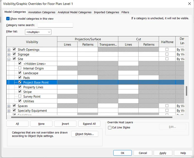
2. Open the Visibility graphic dialog box by typing VG
3. Select the Site section and expand it
4. Then tick mark the project base point option and close the dialog box
Step 6:
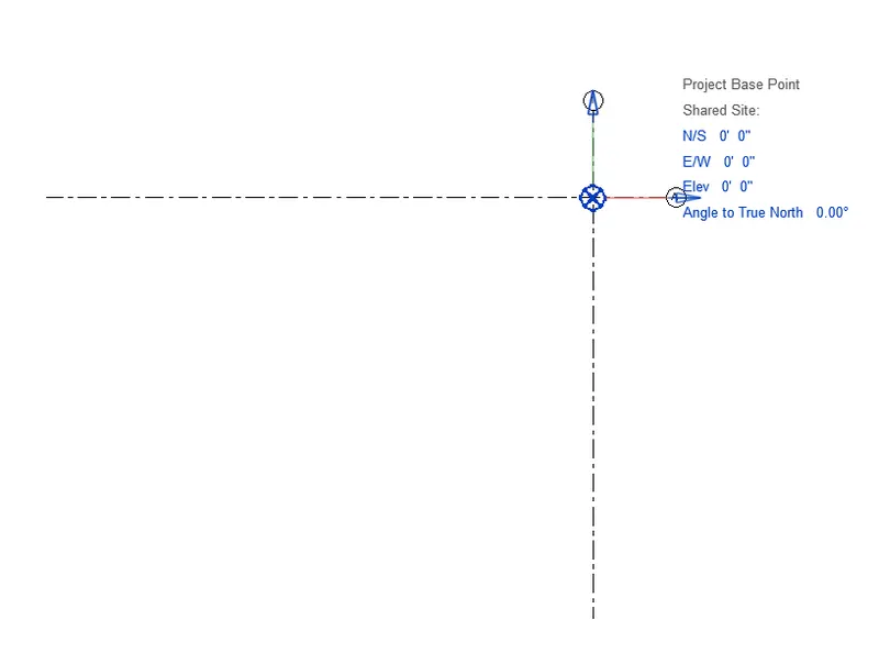
1. Move the project base point symbol to the intersection of horizontal and transverse grids' base point
2. Provide the coordinates again for the project base point if it is mismatched
RESULT:
Project base point and Project shared coordinates have been set successfully for the architectural template file.
2) Open another new file but with a structural template. Using the manage tab set project parameters the same as the architectural model. Copy the parameters from the architectural model to the structural template or enter the parameters manually into the structural model
AIM:
To set the project base point and project shared coordinates for the architectural template using the manage tab
INTRODUCTION:
A Revit project has internal coordinates for all the elements that compose the model in a project. Those coordinates are known to this project only. This is sufficient if you have a standalone model whose position is not relevant to other models or a site. However, if you want the position of the model to be known to other linked models, you need to share coordinates.
The project base point can be used to establish a reference for measuring distances and positioning objects about the model.
Initially, in-stock templates, it identifies the origin (0,0,0) of the project coordinate system. Use the project base point as a reference point for measurements across the site. Place it at a convenient location in the model to simplify on-site measurements. In a view, the project base point looks like this:
PROCEDURE:
Step 1:
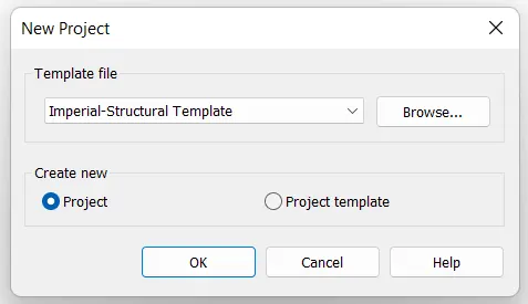
1. Open the Revit Software and click on the new project
2. Select the template file as an architectural template
Step 2:
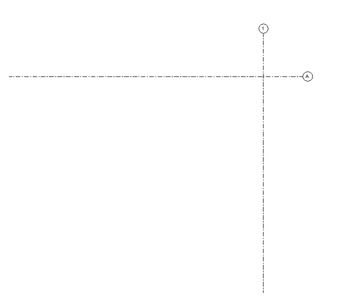
1. Now we have to draw the reference grids for the project base point
2. Select the grid tool from the architectural tab
3. Draw the horizontal and transverse grids as shown in the figure below
Step 3:
1. Now we have to specify the coordinates for the base point
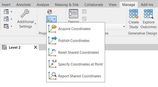
2. Go to the Manage tab and select the project coordinates tool
3. In that section, select the specified coordinates at a point option
Step 4:
1. Select the base point as the intersection of horizontal and transverse grid lines
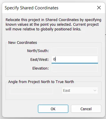
2. Specify the new coordinates as 0'0" for North/South and 0'0" for East/West
3. After providing the coordinates to the base point, click ok
Step 5:
1. Now we have to provide the project base point Symbol
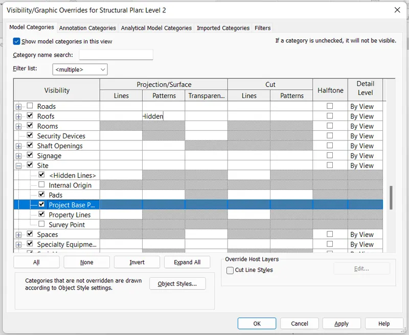
2. Open the Visibility graphic dialog box by typing VG
3. Select the Site section and expand it
4. Then tick mark the project base point option and close the dialog box
Step 6:
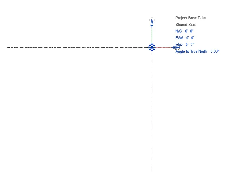
1. Move the project base point symbol to the intersection of horizontal and transverse grids' base point
2. Provide the coordinates again for the project base point if it is mismatched
RESULT:
Project base point and Project shared coordinates have been set successfully for the Structural template file.
3) Re-open the architectural model. Using the tools under the Collaborate tab makes the architectural model a central model (enabling simultaneous working on the model)
AIM:
To re-open the architectural template and set the architectural template as a central model using collaborate tab
INTRODUCTION:
Revit provides several different ways to collaborate with team members who are also using the software.
- You can link multiple Revit models together, allowing team members to work in context.
- Through work sharing, users on the same local area network (LAN) can work together in the same Revit model.
- When collaboration needs to occur among users who are not in the same geographic location, use Revit Server or Revit Cloud Worksharing.
Revit Server connects offices that share a network but are not in the same geographic location.
Revit Cloud Worksharing is a cloud-based service that allows any Revit users inside or outside a network to collaborate on a Revit model.
PROCEDURE:
Step 1:
1. Re-open the architectural tab template that has been created earlier
2. Go to Collaborate tab and select the Collaborate option
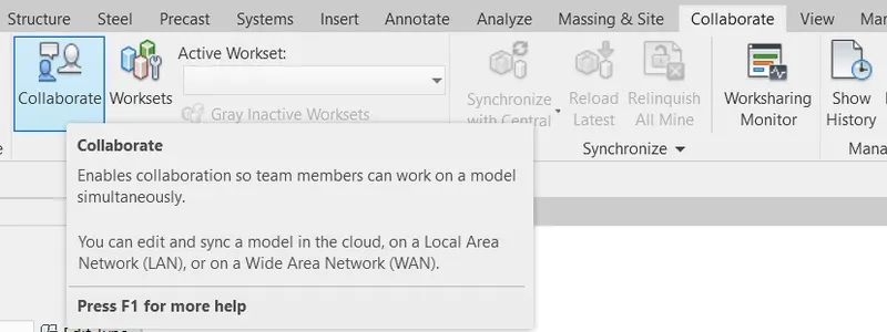
Step 2:
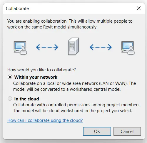
1. After clicking the collaborate option, it will open the collaborate dialog box
2. Now select the option as within your network and press Ok
Step 3:
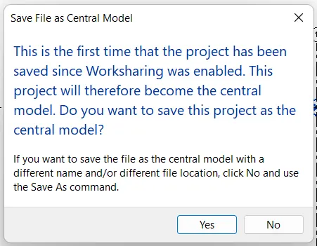
1. Now go to the File tab and save it again after collaborating
2. It will ask for the confirmation showing, (This is the first time that the project has been saved since work sharing was enabled)
3. Now click on the Yes option and save the file as a Central model
RESULT:
The Architectural template has been saved successfully as a Central model using collaborate tab
4) Create the Grids Longitudinal and Transverse pattern for the project similar to the task done in Week 2
AIM:
To create the grids longitudinally and transversely for the Architectural template similar to the task done in Week 2
INTRODUCTION:
Grids are extremely useful for plotting out your drawings and can have many uses. After creating your levels in a new project is a common second step: adding grid lines.
- Gridlines are 3-Dimensional and have a height so can exist on multiple levels
- When placing multiple grid lines Revit will follow your naming convention (1,2,3 A, B, C, etc.)
- You can hide gridlines when you don’t need to use them, more on that later.
PROCEDURE:
Step 1:
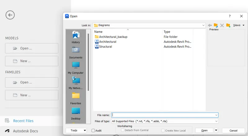
1. Open the Revit software and click on the load option
2. Select the file as the architectural template file that we created earlier
Step 2:
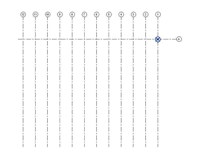
1. Now select the grid tool in the architectural tab
2. Select the Pick Line option in the modify tab and give the Offset distance as 10'
3. Draw the grids transversely aligned to each other at a distance of 10' as shown in the figure below
Step 3:
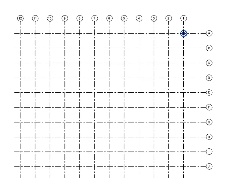
1. Similarly, now we have to draw the horizontal grids
2. Select the grid tool again and select the pick line option
3. Now draw the grids Horizontally at a distance of 10' as shown in the figure below
4. After Creating the grids, Name the grids appropriately according to the convenience
RESULT:
The Longitudinal and Transverse grids for the architectural template have been created successfully
5) Synchronize the changes from the local copy to the central file of the architectural model.
AIM:
To synchronize the changes from the local copy to the central file of the architecture model
INTRODUCTION:
Worksharing is a design method that allows multiple team members to work on the same project model at the same time. On many projects, team members are assigned a specific functional area to work on. Revit projects can be subdivided into worksets to accommodate such environments.
When we working on work shared project, use the Synchronize with Central tool to save your local changes to the central model
PROCEDURE:
Step 1:
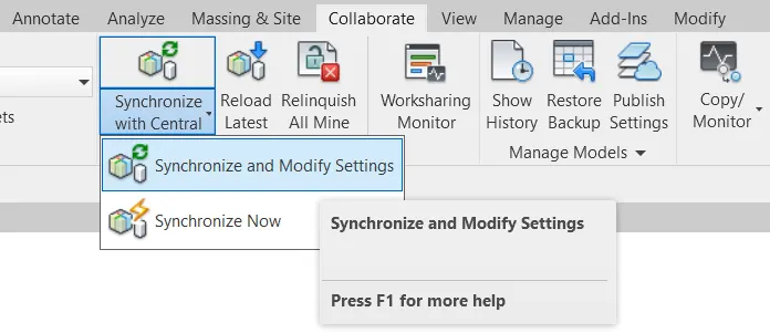
1. After doing any changes in the local copy of the architectural template, now we have to synchronize it
2. Go to Collaborating tab and select the option called synchronize with central
Step 2:
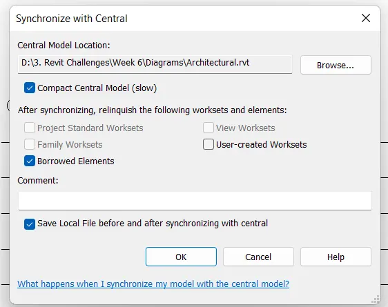
1. After clicking on the synchronize with the central option, a dialog box will appear
2. Select the destination location to save changes for the central model
3. Tick mark the compact central model option in the dialog box
4. Now click on ok to synchronize the local copy to the central model
RESULT:
The architectural template of the project has been successfully synchronized from the local copy to the central model
6) Open the structural model and use the collaboration tools to save the model as a central file.
AIM:
To re-open the architectural template and set the architectural template as a central model using collaborate tab
INTRODUCTION:
Revit provides several different ways to collaborate with team members who are also using the software
Revit Server connects offices that share a network but are not in the same geographic location.
Revit Cloud Worksharing is a cloud-based service that allows any Revit users inside or outside a network to collaborate on a Revit model.
PROCEDURE:
Step 1:
1. Re-open the architectural tab template that has been created earlier
2. Go to Collaborate tab and select the Collaborate option
Step 2:
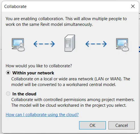
1. After clicking the collaborate option, it will open the collaborate dialog box
2. Now select the option as within your network and press Ok
Step 3:
1. Now go to the File tab and save it again after collaborating
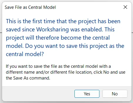
2. It will ask for the confirmation showing, (This is the first time that the project has been saved since work sharing was enabled)
3. Now click on the Yes option and save the file as a Central model
RESULT:
The Architectural template has been saved successfully as a Central model using collaborate tab
7) Under the Collaborate tab, select the grids and levels from the architectural model, and using Copy Monitor try to copy the grids to the structural model. See what happens when the copy monitored grid is moved around in the structural model
AIM:
To copy the grids and levels from the architectural model to the structural model using the copy monitor tool under collaborate tab
INTRODUCTION:
The Copy/Monitor tool is designed for use with important building model elements to streamline coordination and collaboration on a project that involves multiple teams.
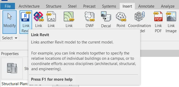
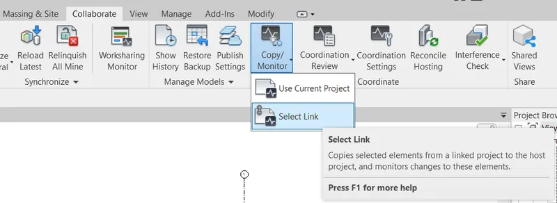
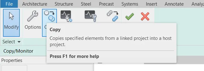
When you start the Copy/Monitor tool, choose Select Link, and then select Copy, you can copy elements from a linked model to the current model, and monitor changes to the original elements.
PROCEDURE:
Step 1:
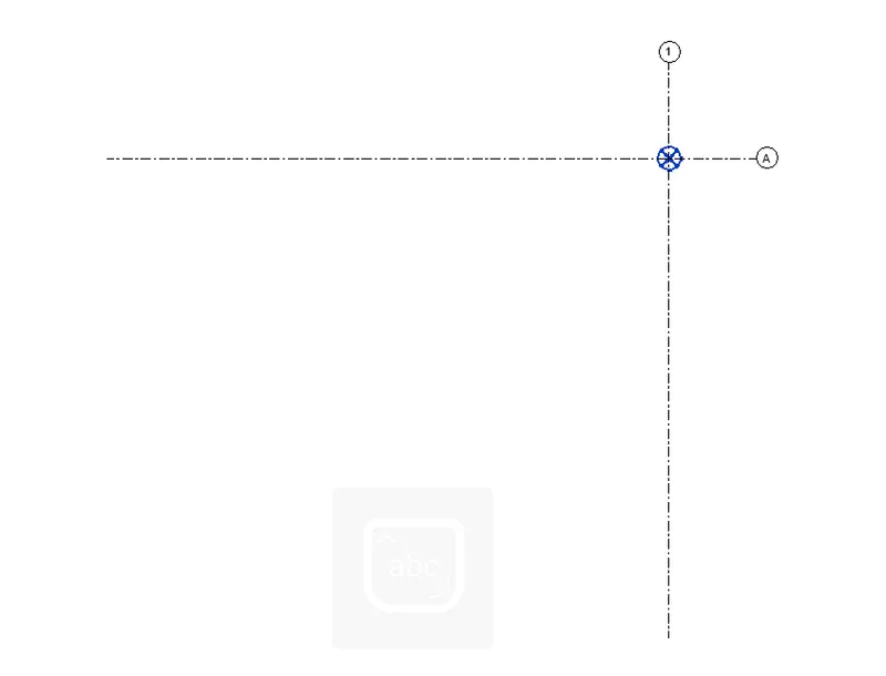
1. Open the Revit software and click on the Load option
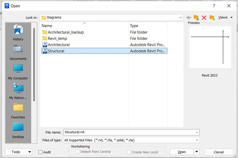
2. Open the Structural file that we created earlier
Step 2:
1. Now we have to copy the architectural elements into structural elements
2. Go to the insert tab and select the option called Link Revit
Step 3:
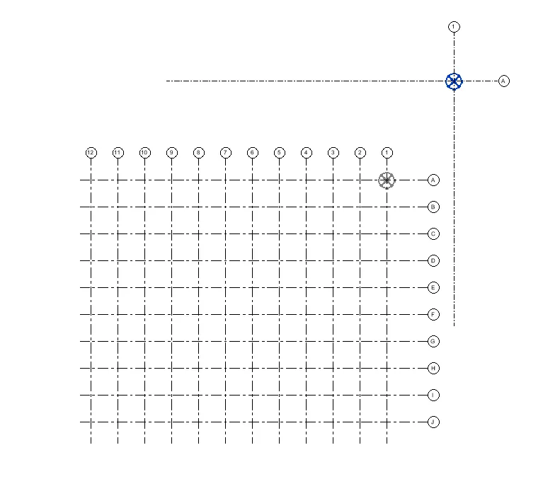
1. After clicking on the link Revit, open the architectural file we created earlier
2. After Selecting the architectural file, it will link to the current model as shown in the figure below
Step 4:
1. Now go to Collaborate tool and select the Copy/Monitor tool
2. In that section, select the option called Select link
Step 5:
1. After Selecting the link, now select the architectural file that we linked into this model
2. Now Select the copy tool from the copy/monitor modify tab
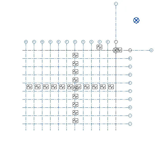
Step 6:
1. Select the Multiple options in the copy/monitor modify tab
2. Select all the architectural elements such as levels and Grids as shown in the figure below
Step 7:
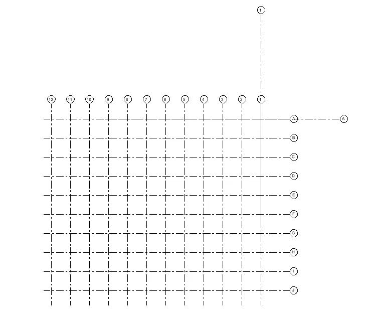
1. After Selecting the elements in the architectural file click the tick mark on the copy/monitor modify tab
2. Now the architectural elements have been copied to the structural model as shown in the figure below
RESULT:
The grids that we drew in the architectural model have been successfully copied to the structural model using the Copy/monitor tool under collaborate tab
8) Create another new file with a construction template. Save the new file as a central model. This file will include both architectural and structural models. Under the manage tab, Click manage links to link both architectural and structural files. Save the file and close all the files.
AIM:
To Create a new construction template file and link the architectural and structural model to the construction model
INTRODUCTION:
The Manage Links dialog has tabs for Revit models, IFC links, CAD Formats, DWF Markups, Point Clouds, and Topography. Under the tabs are columns that provide information about the link. The Manage Links dialog has tabs for Revit models, IFC links, CAD Formats, DWF Markups, and Topography. Under the tabs are columns that provide information about the link.
PROCEDURE:
Step 1:
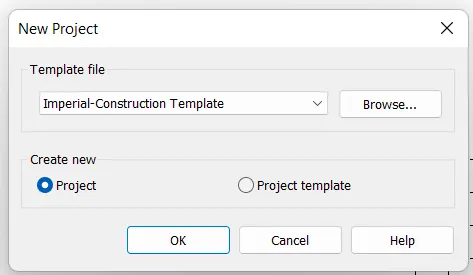
1. Open the Revit software and click on the new project
2. Select the template file as Imperial construction template
Step 2:
1. After Opening the Construction template
2. Go to Collaborate tab and select the Collaborate option
Step 3:
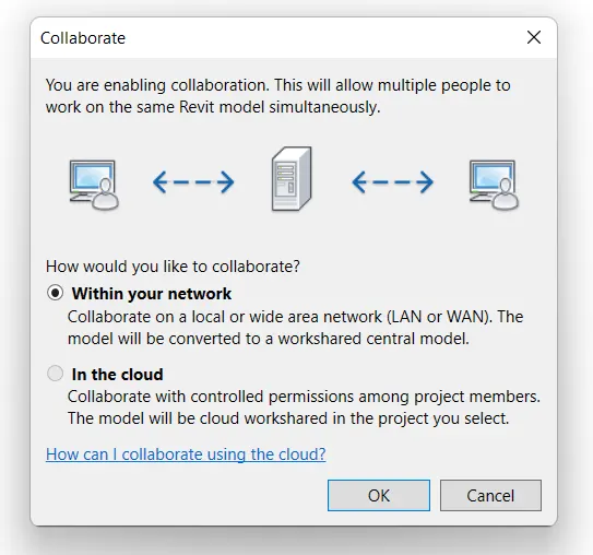
1. After clicking the collaborate option, it will open the collaborate dialog box
2. Now select the option as within your network and press Ok
Step 4:
1. Now go to the File tab and save it again after collaborating
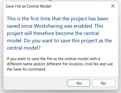
2. It will ask for the confirmation showing, (This is the first time that the project has been saved since work sharing was enabled)
3. Now click on the Yes option and save the file as a Central model
Step 5:
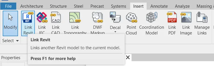
1. Now we have to link the architectural and structural files to the construction model
2. Go to the insert tab and select the option called Link Revit
Step 6:
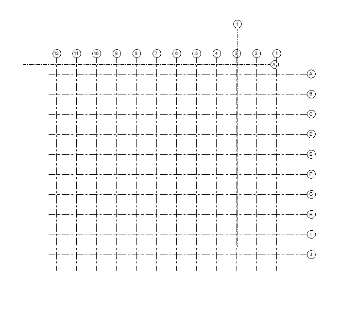
1. After clicking on the link Revit, open the architectural file we created earlier
2. After Selecting the architectural file, it will be linked to the current model as shown in the figure below
Step 7:
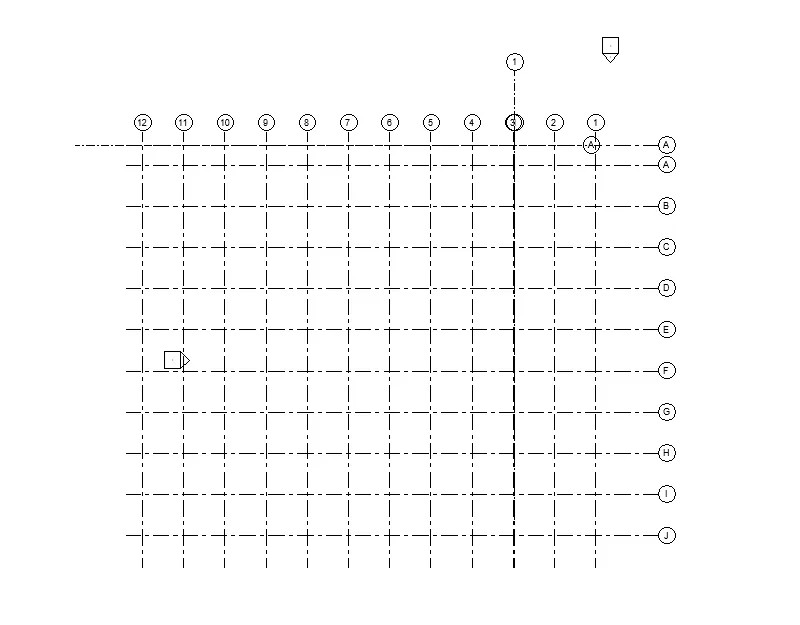
1. Similarly, go to the insert tab again and click on the link Revit
2. This time, we have to link the structural file to the construction model
3. Do the same process as we did for the Linking of architecture template
RESULT:
9) Are the grids from the structural and architectural model matching in the construction template created? If yes the model is set up for project 2. If not work on the shared parameters and linking options under Manage links
( Hint: origin to origin, by shared coordinates, or by project base point to base point ) to link the models in an appropriate manner
Answer:
In my model, all the grids and levels from the architectural and structural models have been matched in the construction template.
I have been worked on shared parameters and linking options successfully and no errors found in the construction model.
The Architectural and structural model has been linked to the construction model has been shown in the figure below
RESULT:
All the grids from the architectural and structural model have been matched successfully to the construction model
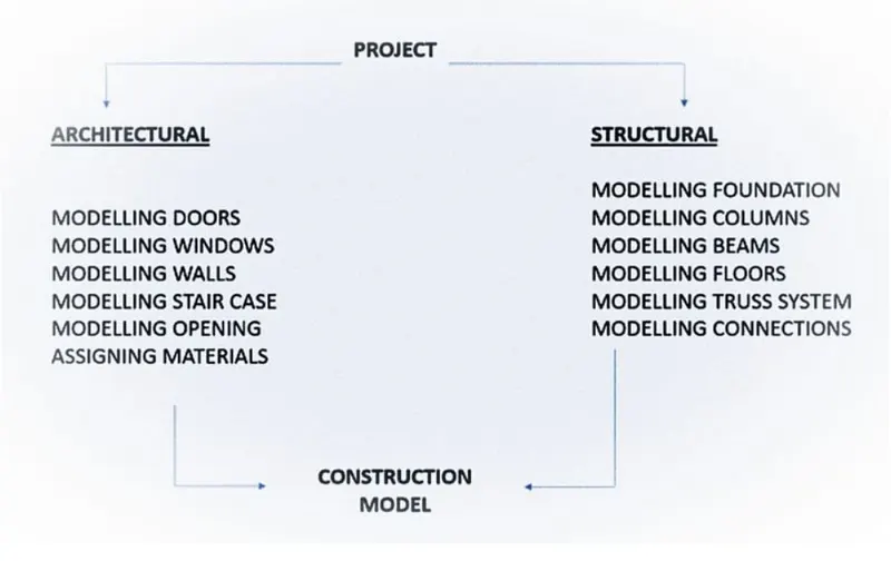
10) List a flow chart of a project tree set up in terms of the Construction model, Architecture & Structure model, in this exercise and understand how many people can work on the same project using Revit simultaneously
AIM:
To list a flow chart of a project tree set up in terms of construction model, architectural model, and structural model
INTRODUCTION:
When we start a new Revit project most likely it will be based on a template. Revit comes with several templates pre-installed ranging from Architectural Templates to Structural Templates. These template files are the starting points of your projects and are designed to save you time setting up a new project.
PROCEDURE:
The construction model has been categorized into two different types we work on Architectural model and the structural model.
The architectural model involves:
- Modelling walls
- Modelling windows
- Modelling doors
- Modelling materials
- Modelling architectural floorings
- Modelling architectural roofings and ceilings
- Modelling staircases
- Creates openings
- Enables to provide the geographic conditions
The architectural model overall contributes to the aesthetic beauty of the building
On other hand, the Structural model involves:
- Modelling columns
- Modelling beams
- Modelling foundations
- Modelling structural floors
- Modelling labs
- Modelling Reinforcements
- Modelling Connections
A structural model in general develops the entire framework of a structure
RESULT:
The flow has been created successfully describing the terms of construction, architectural and structural model