Creating a Residence Layout, Seating plan, Toilet and Utility room plan using AutoCad
AIM:
To Sketch the plans given in the diagram by using AutoCAD:
INTRODUCTION:
Layers in AutoCAD:
• Layers are the primary method for organizing the objects in a drawing by function or purpose.
• Layers can reduce the visual complexity of a drawing and improve display performance by hiding information that you don't need to see at any moment in time
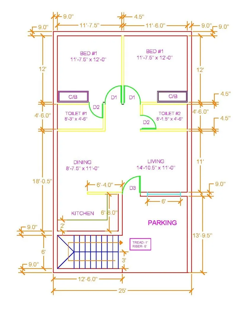
#Sketching Figure 1:
To Sketch the layout of a residence plan as per the given diagram using AutoCAD.
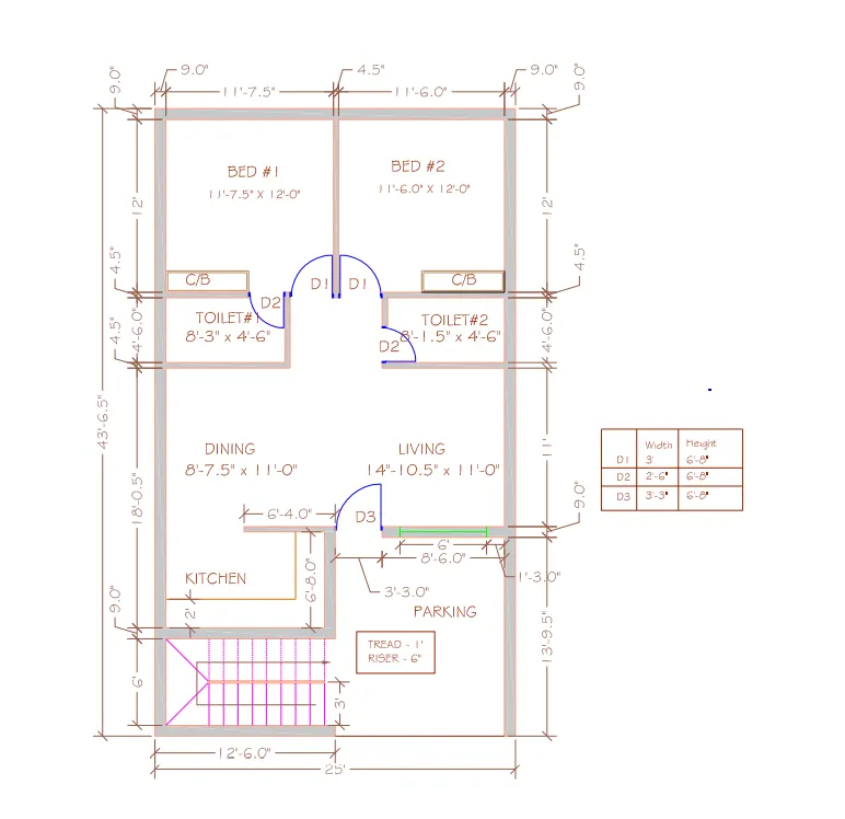
Commands Used:
1. Units
2. Limits
3. Xline
4. Trim
5. Offset
6. Line
7. Arc
8. Move
9. Rotate
1. Dimension
11. Text
12. Layer
Procedure :
1. First set the unit by typing the command
2. Type 'UN' or 'Units' in the command box and press enter. Select units as engineering > 0'-0.00" > inches and click OK.
3. Type 'LIM' or 'LIMITS' in the command box and set the limits as 0,0 and 100',100' and press enter
4. Press "Z" > Enter > "A" > Enter for full screen
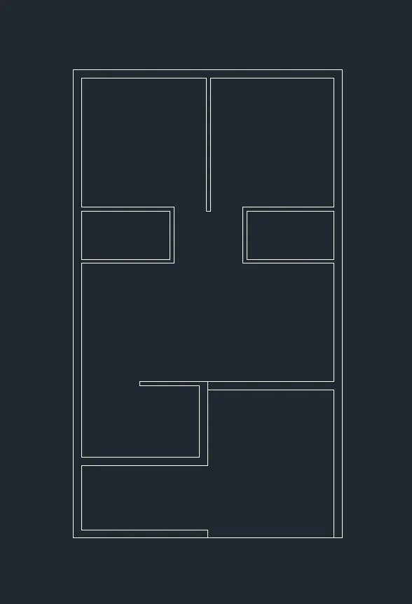
Step 1:
1. Type "XL" in the command box and press enter for construction line
2. Create vertical and horizontal lines by clicking the cursor on the screen randomly
3. Type "TR" for trim command and trim the extra lines
4. Type the command "O" for offset and take the offset distance of 9" from both construction lines.
5. Type the command "O" for offset and take the offset distance of 6' from the top horizontal line.
6. Type the command "O" for offset and take the offset distance of 9" from the offset line
7. Type the command "O" for offset and type the offset distance of 6'8" from the top horizontal line.
8. Type the command "O" for offset and take the offset distance of 4.5" from the offset line.
9. Type the command "O" for offset and take the offset distance of 11" from the top horizontal line
10. Type the command "O" for offset and take the offset distance of 4.5" from the offset line.
11. Type the command "O" for offset and take the offset distance of 4'6" from the top horizontal line
12. Type the command "O" for offset and take the offset distance of 4.5" from the offset line
13. Type the command "0" for offset and take the offset distance of 12' from the top horizontal line.
14. Type the command "O" for offset and take the offset distance of 9" from the offset line.
15. Type the command "O" for offset and take the offset distance of 11'7.5" from the vertical line.
16. Type the command "O" for offset and take the offset distance of 4.5" from the offset line.
17. Type the command "O" for offset and take the offset distance of 11'6.0" fromhL the vertical line.
18. Type the command "O" for offset and take the offset distance of 9" from the offset line.
19. Type the command "O" for offset and take the offset distance of il' from the vertical line.
20. Type the command "O" for offset and take the offset distance of 9" from the offset line.
21. Now type the command "TR" and trim all the extra lines.
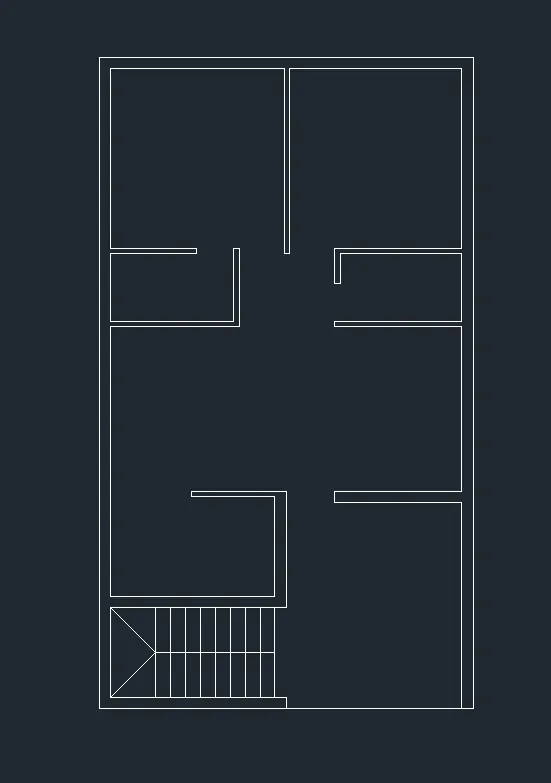
Step 2:
1. Type the command "O" for offset and take the offset distance of 3' from the vertical external line.
2. Type the command "O" for offset and take the offset distance of a from the offset line for 8 times in +ve X direction for creating steps of stairs.
3. Type the command "O" for offset and take the offset distance of 3' from the horizontal external line for railings of stairs.
4. Type "L" for line command then press enter and join the corners to the railing point.
5. Type "L" for line command then press enter and make the path with arrow end to show the direction of stairs.
6. Now type the command "TR" and trim all the extra lines.
Step 3:
1. Type "L" for line command and then press enter anywhere on the screen to create a line in -ve X-direction of length .5" and specify the next point of length 3' in +ve Y-direction.
2. Type "A" for arc and specify bottom of the linen as center and top of that line as the first point and then specify the arc angle as 90 degrees.
3. Now select the whole door and type "MO" for the move command and place it where the gap for the door is 3'.
4. Use the "RO" command for rotation to fix the door in proper alignment.
5. Now type the command "TR" and trim all the extra lines.
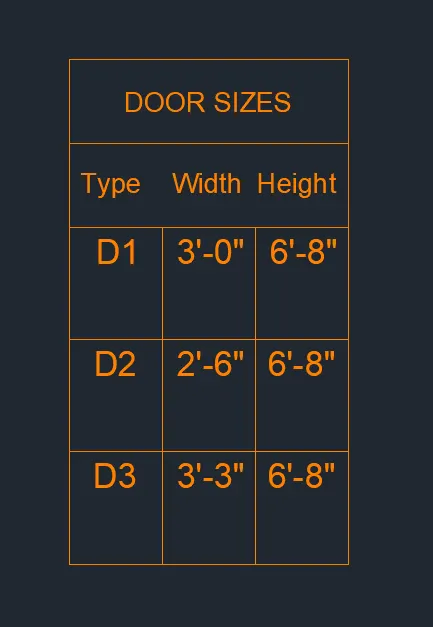
6. Now repeat the above steps for creating doors of size 2'6" • and 3'3".
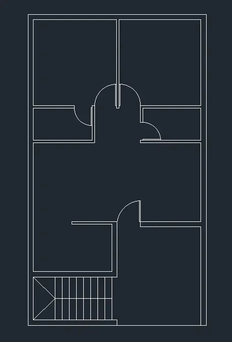
Step 4:
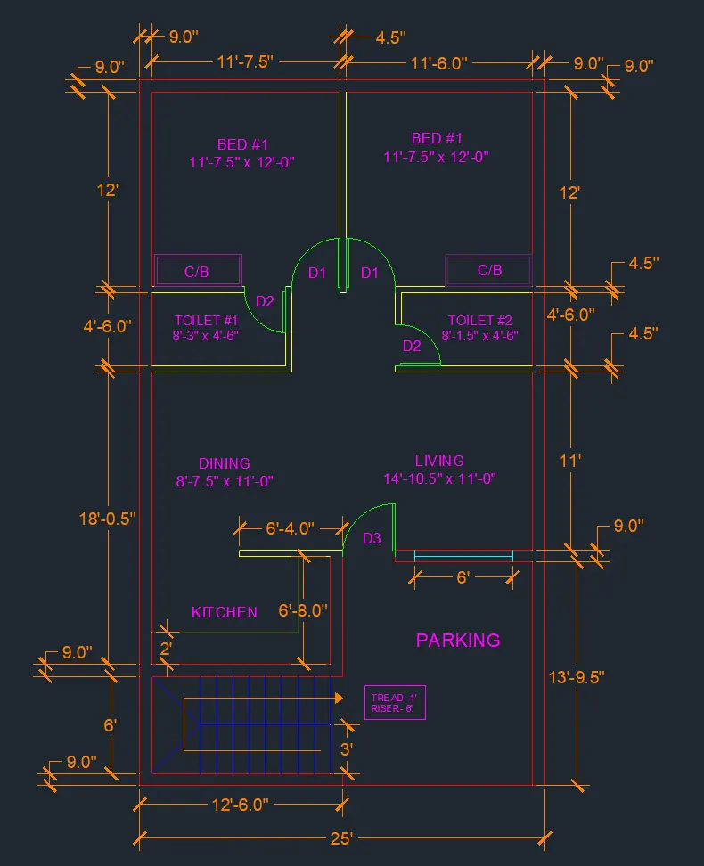
1. Type "D" and then press enter for dimension style management.
2. Set the dimension properties as per requirement.
3. Type "DIM" in the command box for dimension.
4. Specify the start and endpoints of the objects whose dimension is to measure and then click the mouse button.
Step 5:
1. Select the "TEXT" command from the ribbon to create the text.
2. Specify the first and last corner.
3. Type the Text on the box and click anywhere on the screen to exit the command.
4. Edit the height of the text by selecting the text and by right-clicking and selecting the properties option.
Step 6:
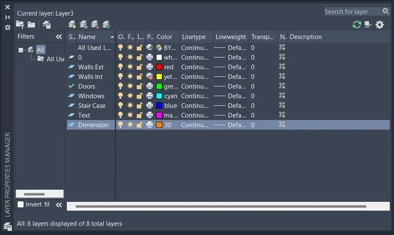
1. Type "LA" and press enter to open layer property manager box.
2. Create new layers by clicking on the new layer icon or right-click on an existing layer and select a new layer.
3. Give names to the layers and assign different colors and line types
4. Select the different components of drawing and assign the layers to them.
Layers can be created as :
RESULT:
1. Door Dimensions:
2. Plan:
#Sketching Figure 2:
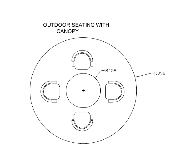
To Sketch the seating plan for an outdoor canopy using AutoCAD:
Commands Used:
1. Units
2. Limits
3. Circle
4. Rectangle
5. Line
6. Arc
8. Offset
9. Trim
10. Copy
11. Rotate
12. Move
13. Dimension
Procedure :
1. Type "UN" in the command box and press enter.
2. Select the type as "Decimal" and scale inserted content as "Millimeters" and Clik "OK".
3. Type 'LIM' or 'LIMITS' in the command box and set the limits as 0,0 and 100',100' and press enter
4. Press "Z" > Enter > "A" > Enter for fullscreen
Step 1:
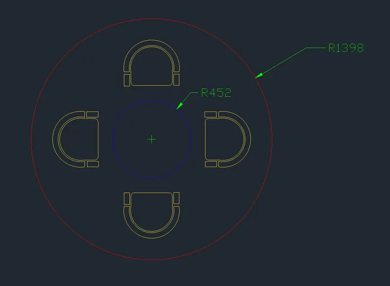
1. Type "C" for circle and press enter. • Specify any point on the screen as a center and specify radius as 452 mm and press enter.
2. Again type "C" for circle and press enter. Specify the same center and specify radius as 1398 mm and press enter.

Step 2:
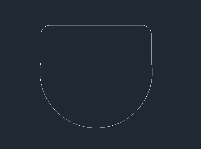
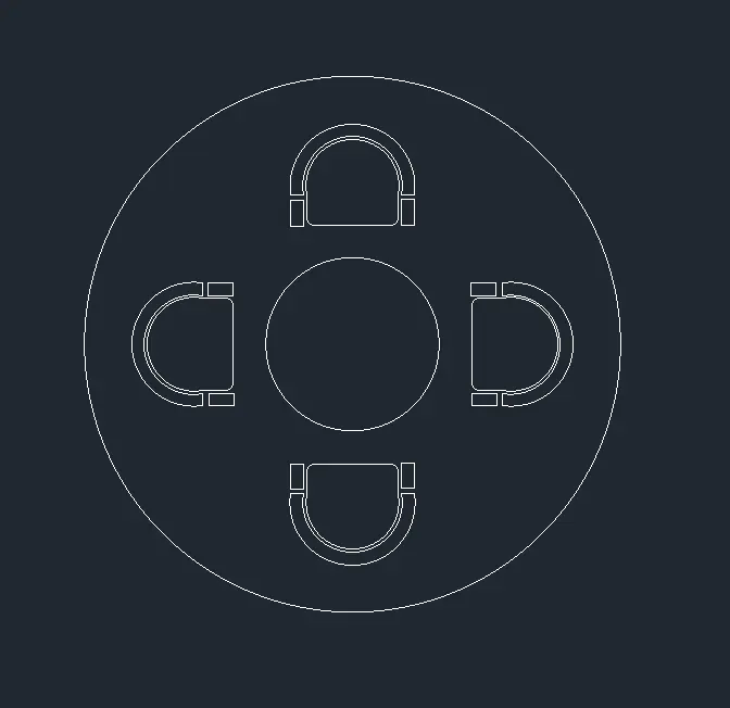
1. Now we have to draw chairs around the circular table
2. Take a 'Rectangle' of size 800×300 and press enter
3. Take any two corners of the rectangle and fillet those corners of radius 100
4. Take 'Arc' Command and select start, end, direction
5. Draw the arc at our convenient starting from the bottom left corner to the bottom right corner of the rectangle
6. Type 'Trim' in the command box and trim the middle line in arc and rectangle as shown in the figure below
Step 3:
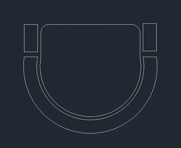
1. Take the 'Offset' command
2. Select offset distance as 30
3. Select object as arc and Offset it through -Y-axis
4. Select the 'Offset' command again and now give the offset distance as 100
5. Select the 'Line' command and close both left and right sides of the arcs
6. Now select the 'Rectangle' command and draw two rectangles of size 100×200 and put this rectangle as proper position as shown in the figure below
Step 4:
1. Select the 'Copy' command and take 4 copies of the above chair
2. Select the 'Rotate' command and rotate the chair at 90, 180, and 270 respectively
3. Select 'Move' command Move all the chairs and place them in the proper position as shown in the figure below
Step 5:
1. Give Dimensions as per drawing by typing 'DIM' in the command box
2. Select the Layer option and give different layers to the drawing
RESULT:
#Sketching Figure 3:
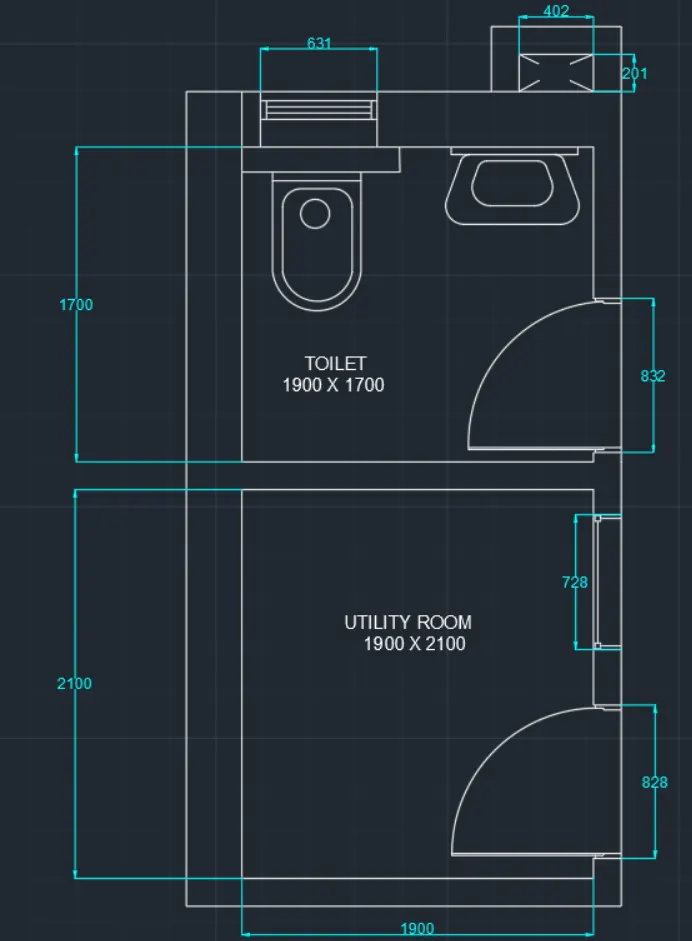
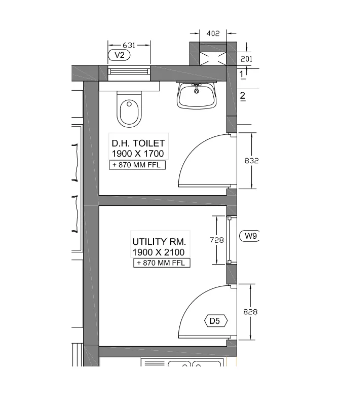
To sketch the part plan for the toilets and utility room using AutoCAD:
Commands Used:
1. Units
2. Limits
3. Xline
4. Offset
5. Trim
6. Rectangle
7. Arc
8. Dimension
Procedure :
1. Type "UN" in the command box and press enter.
2. Select the type as "Decimal" and scale inserted content as "Millimeters" and Clik "OK".
3. Type 'LIM' or 'LIMITS' in the command box and set the limits as 0,0 and 100',100' and press enter
4. Press "Z" > Enter > "A" > Enter for fullscreen
Step 1:
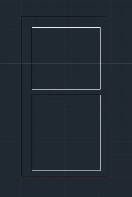
1. Type "XL" in the command box and press enter for construction line. Select Vertical and horizontal lines one by one and click on the screen anywhere.
2 Type "TR" for trim command and trim the extra line to create the Bottom-Left border of the plan.
3. Type the command "O" for offset and specify the offset distance of 300mm and select the vertical Xline and click the cursor on the right side.
4. Type the command "O" for offset and specify the offset distance of 150mm and select the horizontal Xline and click the cursor on the right side.
5. Type the command "0" for offset and specify the offset distance of 1900mm and select the vertical Xline and click the cursor on the right side.
6. Type the command "O" for offset and specify the offset distance of 150mm and select the vertical Xline and click the cursor on the right side.
7. Type the command "O" for offset and specify the offset distance of 2100mm and select the horizontal Xline and click the cursor in an upward direction.
8. Type the command "O" for offset and specify the offset distance of 150mm and select the horizontal Xline and click the cursor in an upward direction.
9. Type the command "O" for offset and specify the offset distance of 1700mm and select the horizontal Xline and click the cursor in an upward direction.
10. Type the command "0" for offset and specify the offset distance of 300mm and select the horizontal Xline and click the cursor in an upward direction.
11. Type "TR" for trim command and trim the unnecessary lines.
Step 2:
1. Select 'Rectangle' from the ribbon tab.
2. Specify the starting point of the rectangle as an internal top-left corner point.
3. Select dimension from the command box and specify the length as "402" and width as "201" and press enter.
4. Type the command "O" for offset and specify the offset distance of 150mm and select the rectangle and click the cursor in an outward direction. Press "ESC".
5. Type "TR" in the command box and trim the extra and unnecessary lines.
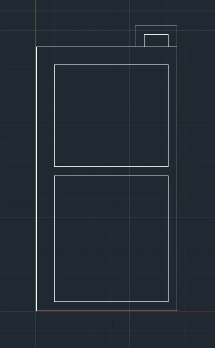
Step 3:
1. Type the command "O" for offset and specify the offset distance of 100mm and select the upper room mid horizontal line and click the cursor in an upward direction just for reference.
2. Extend that line into the thickness of the right side wall and trim the previous line.
3. Type the command "O" for offset and specify the offset distance of 832mm and select the previous line and move the cursor in an upward direction and click escape
4. Use the 'Trim' command and trim the useless lines.
5. Draw the door of width 832mm using the rectangle command.
6. Select the 'Arc' tool from the ribbon tab and specify the start point, endpoint and direction as specified in the sketch.
7. Repeat the above same procedure to draw the next door of length 828mm.
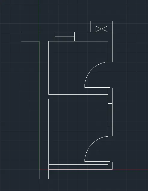
Step 4:
1. Type the command "O" for offsetting and specify the offset distance of 100mm and select the top-left line and click the cursor on the right side and press "ESC".
2. Type the command "O" for offsetting a specify the offset distance of 631mm and select the last offset line and click the cursor on the right side and press "ESC".
3. Select the 'Rectangle' tool from the ribbon tab and draw small rectangles of random size inside the offset lines and join the edges of the rectangle by using the line command.
4. Type the command "O" for offset and make two more offsets in between equal distances and press ESC.
5. Draw a horizontal line at the middle right side using a line tool from the ribbon tab.
6. Type the command "O" for offsetting a specify the offset distance of 728mm and select the line and click the cursor in downward direction and Press "ESC".
7. Use the 'line' command and draw a line in between the window and draw the small rectangles at each end of the line by using the "rec" command
Step 5:
1. Draw the Toilet and Washbasin as given in the sketch by using line, fillet, and circle commands.
2. Type "TR" for trim command and press enter
3. Then trim the unwanted or extra lines or components.
4. Give Dimensions as per drawing by typing 'DIM' in the command box
RESULT: