Creating various 3D Models like Furniture, Footing, Girder, Column drop with panel and Gable Wall in AutoCad
Creating various 3D Models like Furniture, Footing, Girder, Column drop with the panel, and Gable Wall in AutoCad
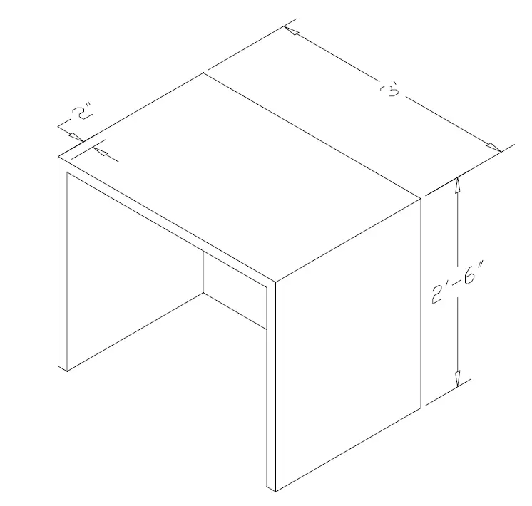
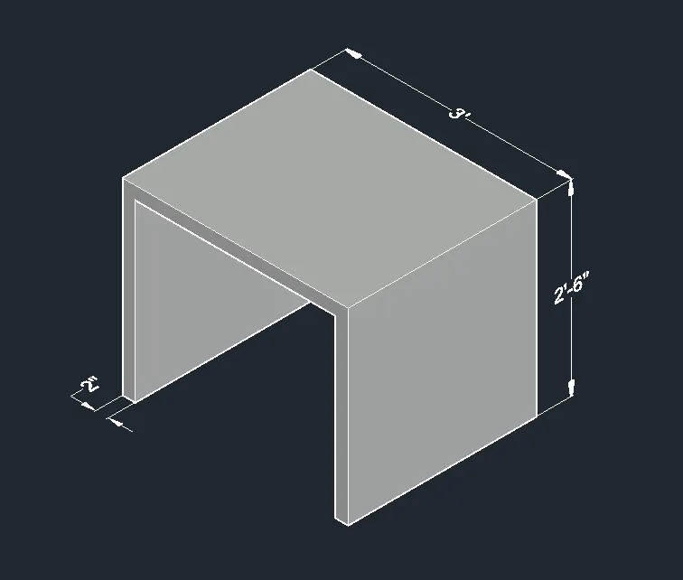
1. Create a 3D Furniture element as shown in the Figure. Assume dimensions that are missing.
AIM:
To create a 3D model of the Furniture element as per the given drawing
INTRODUCTION:
3D modeling in AutoCAD includes 3D solids, surfaces, meshes, and wireframe objects.
Types of 3D Models:
Several types of 3D modeling are available in AutoCAD. Each of these 3D modeling technologies offers a different set of capabilities.
- Wireframe modeling is useful for initial design iterations and as reference geometry, serving as a 3D framework for subsequent modeling or modification.
- Solid modeling is efficient to use, easy to combine primitives and extruded profiles, and offers mass properties and sectioning capabilities.
- Surface modeling offers fine control over curved surfaces for precise manipulation and analysis.
- Mesh modeling provides freeform sculpting, creasing, and smoothing capabilities.
COMMANDS USED:
1. Units
2. Limits
3. Rectangle
4. Line
5. Extrude
6. UCS
7. Move
8. Subtract
PROCEDURE:
Step 1:
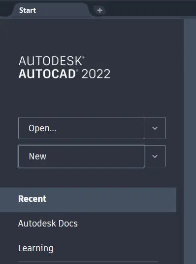
1. Open the Autocad software from the desktop
2. On the home page of the Autocad, Click on New drawing
3. Switch the model space into 3D modeling from the status bar
Step 2:
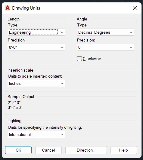
1. Type UN and set the units as Engineering and precision as 0' 0"
2. Set the units as Inches in the insertion scale
3. Type Limits in the command box and set the Lower limit as 0,0 and Upper limit as 50',50'
4. Type Z enter for Zoom Enter and A Enter for Zoom all
Step 3:
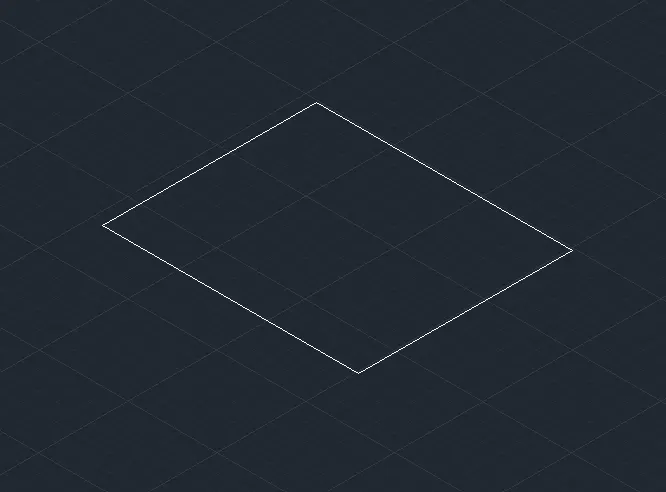
1. In the Top right corner, Select the UCS icon and convert the space into a 3D view
2. Select the Rectangle tool by typing REC or Rectangle in the command box
3. Draw a rectangle with a dimension of length 2'6" and a width of 3'
Step 4:
1. Select the Extrude tool by typing EXT or Extrude in the command box
2. Select the Rectangle and Extrude in an upwards direction
3. Give Extrude height as 2'6" and press Enter

Step 5:
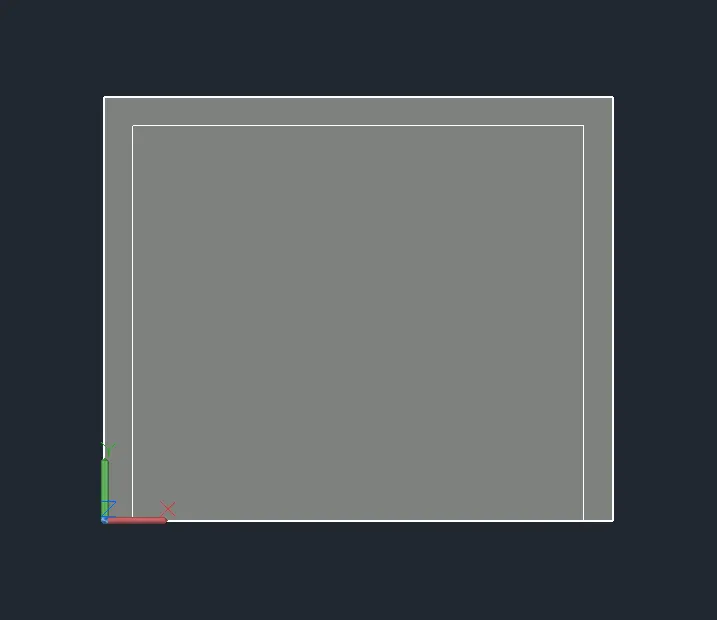
1. Select the Front view from the UCS icon and provide X and Y coordinates in the front face Using UCS Command
2. Select the Line command and draw a line of length 2" from the right side of the front view
3. Select the Rectangle command and draw a rectangle of dimensions 2'8" and 2'4"
4. Move the Rectangle to the line drawn earlier (i.e., 2" line from the right side of the face)
5. After moving the rectangle, delete the previous line that we drew earlier
Step 6:
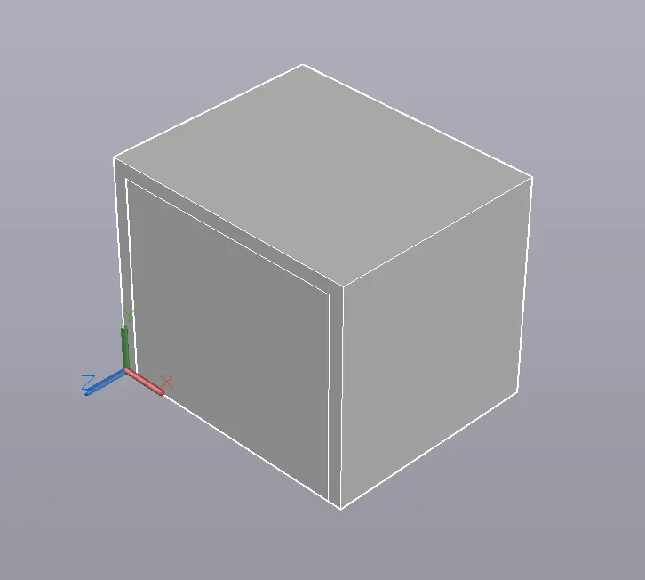
1. Select the Extrude tool by typing EXT or Extrude in the command box
2. Select the Interior rectangle that we drew earlier
3. Extrude the rectangle with the height of 2'4" leaving 2" as thickness
Step 7:
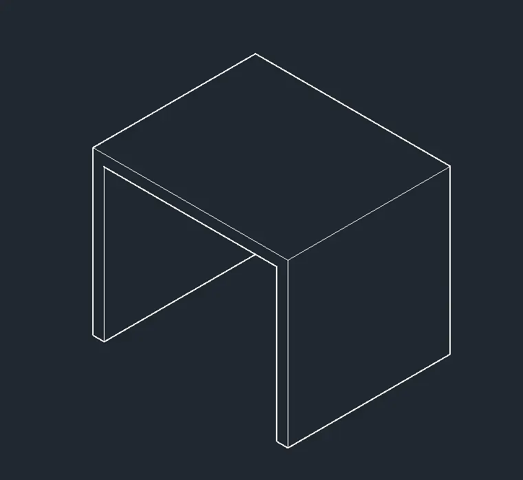
1. Select the Subtract tool by typing Subtract in the command box
2. Select the Exterior Rectangle first and Press enter
3. Then select the Interior rectangle and press enter to subtract the rectangle from the exterior one.
RESULT:
The 3D model of the Furniture element has been sketched successfully as per the drawing
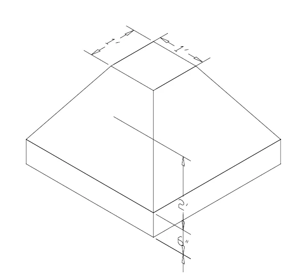
2. Create the 3d Model of an Isolated footing as shown in Figure.
AIM:
To create the 3D model of an Isolated footing as per the given drawing.
INTRODUCTION:
AutoCAD 3d is a powerful CAD software, which is made used for architectural style and mechanical design. It has one of the best toolboxes and features to sustain 2D drawings. Nevertheless, when it involves a 3D layout, it is impressive, with its 3D providing attribute that offers sensational and vivid outputs.
AutoCAD is a three-dimensional CAD software program that is made use of commercially throughout the globe. Established by Autodesk in the year 1982.
AutoCAD is additionally offered as a mobile and web app, which is marketed as AutoCAD 360. AutoCAD uses a special series of commands and functions both for 3D and 2D modeling and attracting with an amazing collection of devices.
COMMANDS USED:
1. Units
2. Limits
3. UCS
4. Rectangle
5. Move
6. Loft
7. Extrude
PROCEDURE:
Step 1:
1. Open the Autocad software from the desktop
2. On the home page of the Autocad, Click on New drawing
3. Switch the model space into 3D modeling from the status bar
Step 2:
1. Type UN and set the units as Engineering and precision as 0' 0"
2. Set the units as Inches in the insertion scale
3. Type Limits in the command box and set the Lower limit as 0,0 and Upper limit as 100',100'
4. Type Z enter for Zoom Enter and A Enter for Zoom all
Step 3:
1. Go to the Top view using the UCS icon at the top right corner
2. Select the Rectangle tool by typing REC or Rectangle in the command box
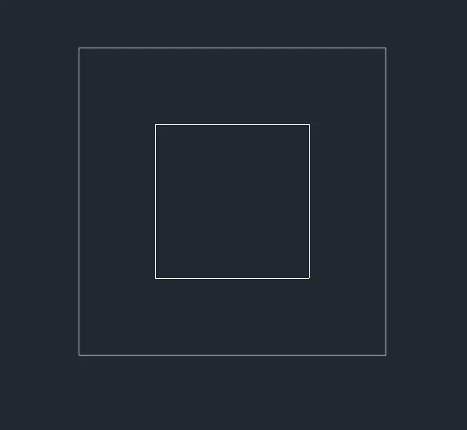
3. Draw a rectangle with dimensions of the length of 2' and a width of 2'
4. Similarly draw another rectangle with dimensions 1'×1' at the center concerning the previous one
Step 4:
1. Go to the default 3D view using the UCS icon at the top right corner
2. Select the Move tool and Select the Interior rectangle
3. Move the rectangle upwards towards the Z direction at a distance of 2'

Step 5:
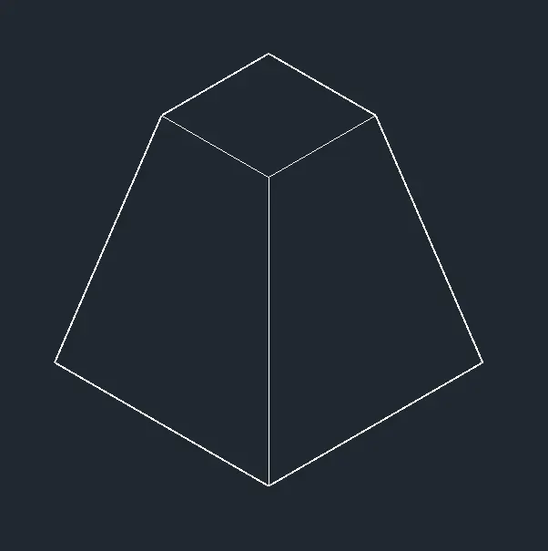
1. Select the Loft tool from the ribbon tab or by typing Loft in the command box
2. Select the Two rectangles and press enter to loft.
Step 6:
1. Now go to the Top view again using the UCS icon
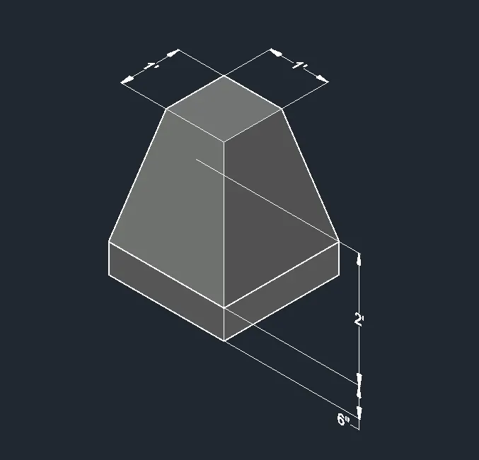
2. Select the Rectangle tool and draw a similar rectangle of 2'×2' at the same position
3. Go to the Default 3D view and Select the Extrude tool
4. Extrude the previously created rectangle to the negative Z Direction with a height of 6" as shown in the figure below

RESULT:
The 3D model of an Isolated footing has been sketched successfully as per the drawing
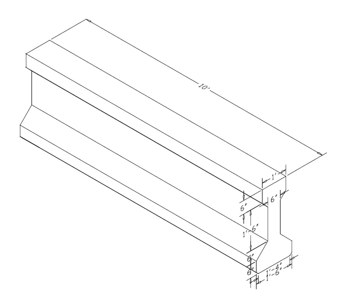
3. Create the 3D view of the AASTHO Type Girder.
AIM:
To Create the 3D view of the AASTHO type of Grider as per the given drawing
INTRODUCTION:
A girder is a support beam used in construction. It is the main horizontal support of a structure that supports smaller beams. Girders often have an I-beam cross-section composed of two load-bearing flanges separated by a stabilizing web, but may also have a box shape, Z shape, or other forms. Girders are commonly used to build bridges
The AASHTO girder is characterized by pre-tensioning as the method of introducing pre-stressing. The below table shows the cross-sectional specifications and maximum span length of AASHTO Type III, V, and VI girders. The maximum span length of the girder shown in the table is the result of applying HS25 load (similar to DB-24 load) and concrete compressive strength of 48MPa based on the short-span bridge.
COMMANDS USED:
1. Units
2. Limits
3. UCS
4. Line
5. Sweep
6. Erase
PROCEDURE:
Step 1:
1. Open the Autocad software from the desktop
2. On the home page of the Autocad, Click on New drawing
3. Switch the model space into 3D modeling from the status bar
Step 2:
1. Type UN and set the units as Engineering and precision as 0' 0"
2. Set the units as Inches in the insertion scale
3. Type Limits in the command box and set the Lower limit as 0,0 and Upper limit as 100',100'
4. Type Z enter for Zoom Enter and A Enter for Zoom all
Step 3:
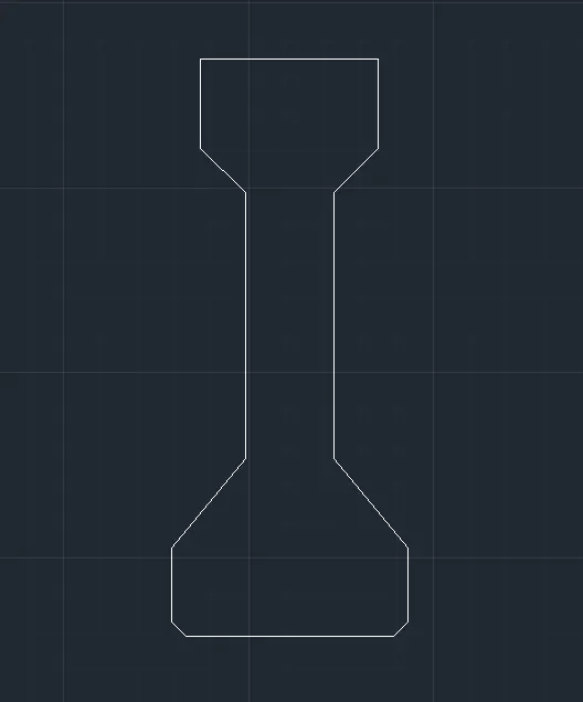
1. Go to the Front view using the UCS icon at the top right corner
2. Select the Line tool by typing L or Line in the command box
3. Specify the starting point of the line as 0,0,0
4. Specify the next point of the line as @1'6",0,0
5. Specify the next point of the line as @0,0,6"
6. Specify the next point of the line as @6"<0<135
7. Similarly follow all the given dimensions to draw the section as shown in the figure below
Step 4:
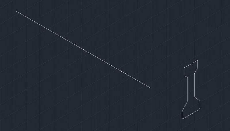
1. Now go to the default 3D view using the UCS icon
2. Select the Line command by typing L or Line in the command box
3. Draw a line of length 10' in the XY plane as shown in the figure below
Step 5:
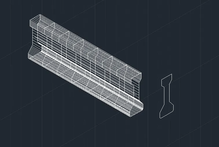
1. Select the Sweep tool on the ribbon tab or by typing Sweep in the command box
2. Select the object to sweep as the Astho Grider that we created earlier and press enter
3. Now, select the path as Line that we created earlier and press Enter
Step 6:
1. After Creating the sweep from the front view of the girder, delete the previous one
2. Now we can see the wireframe sketch of the AASTHO girder
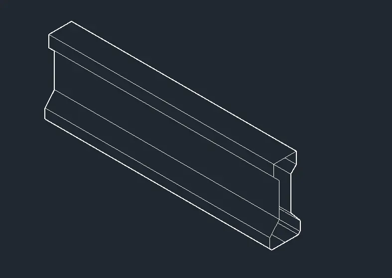
RESULT:
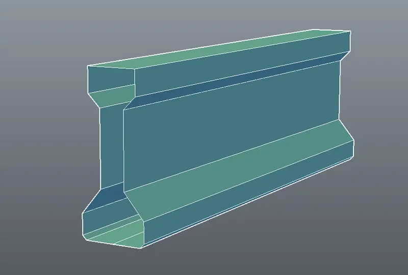
The 3D model of the AASTHO type of girder has been sketched successfully as per the drawing
4. Create a 3d Model of a drop column with the panel as shown in the section and isometric view.
AIM:
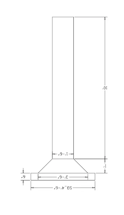
To create the 3D model of a drop column with the panel as shown in the section and Isometric view
INTRODUCTION:
Drop panels are the rectangular portion provided above the column and below the slab to restrict the slab from getting sheared and undergoing rupture.
The drop panel increases the contact surface area between the column and slab, which will enable a better distribution of load from slab to column. Thus, it will reduce the chance of slab failure due to unbalanced moments.
The reasons behind the drop panel's construction are as given below.
- Increase in the flexibility of planning the layout for the room,
- Easier installation of framework and reinforcement,
- The building height is reduced through the provision of extra support,
- Construction time needed for large table frameworks is reduced,
- The auto sprinkling process is easier and
- Welded mesh is of standard size, in the case of a prefabricated one. It requires lesser installation time and also provides more control over construction quality.
The main uses of the drop panel are as below.
- Drop panel tends to improve the competence to resist shear failure, which can happen in the flat slab,
- Drop panel tends to enhance the negative moment capacity of the flat slab and
- Drop panel tends to minimize the deflection through the fabrication of the flat slab.
COMMANDS USED:
1. Units
2. Limits
3. Circle
4. Region
5. Rectangle
6. Extrude
7. Move
8. Cone
PROCEDURE:
Step 1:
1. Open the Autocad software from the desktop
2. On the home page of the Autocad, Click on New drawing
3. Switch the model space into 3D modeling from the status bar
Step 2:
1. Type UN and set the units as Engineering and precision as 0' 0"
2. Set the units as Inches in the insertion scale
3. Type Limits in the command box and set the Lower limit as 0,0 and Upper limit as 100',100'
4. Type Z enter for Zoom Enter and A Enter for Zoom all
Step 3:
1. Go to the default 3D view using the UCS icon
2. Select the Circle tool by typing C or Circle in the command box
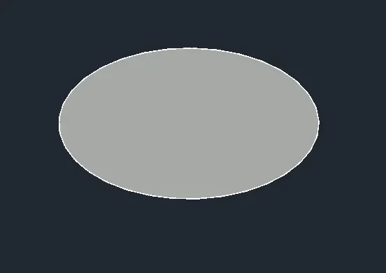
3. Create the circle with a diameter of 1'6" as shown in the figure below
4. Select the Region tool and create a region of the circle that we created earlier
Step 4:
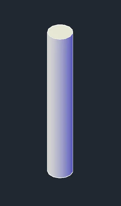
1. Select the Extrude tool by typing EXT or Extrude in the command box
2. Select the Circle and Extrude it into the +Z direction
3. Give Extrude height as 10' and sketch the column as shown in the figure below
Step 5:
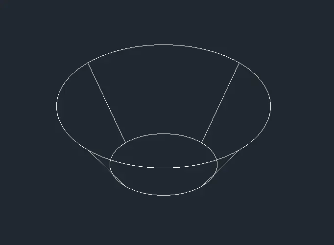
1. Select the Cone tool from the Home ribbon tab
2. Sketch the cone with the base diameter of 1'6"
3. Now click on the Top radius option and give the value is 1'6"
4. Then provide the height of the cone as 1' and sketch the cone as shown in the figure below
Step 6:
1. Go to the Top view using the UCS icon at the top right corner
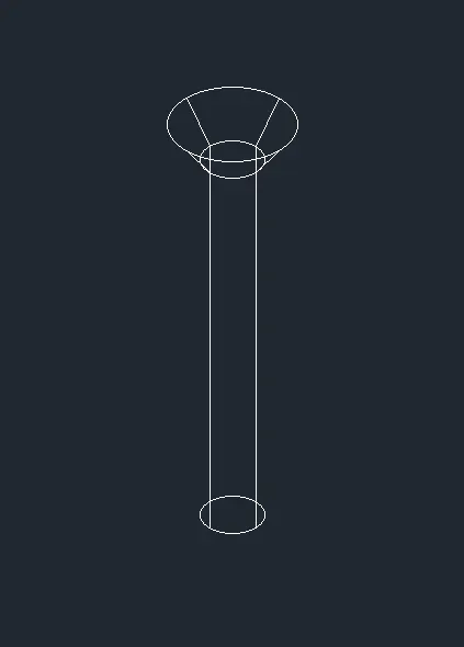
2. Select the Cone that we created earlier and move it into the Extruded circle
3. Now, go to the default 3D view and move the cone from the bottom to the top level at a distance of 10'
4. The frustum with the cone has been sketched as shown in the figure below
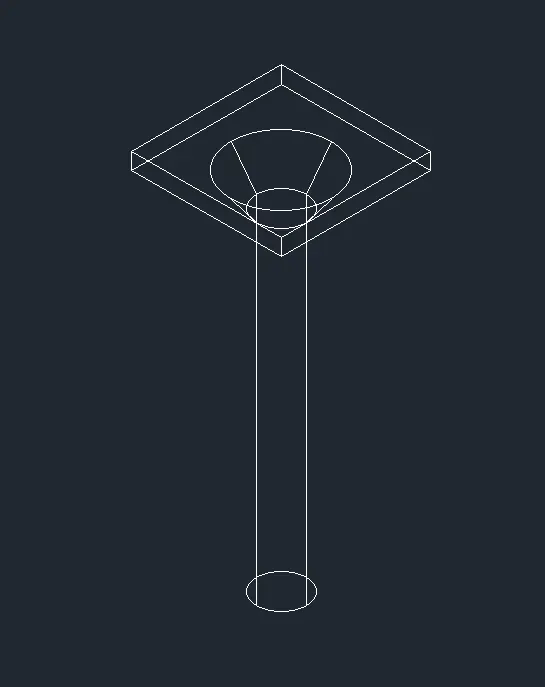
Step 7:
1. Go to the Top view again using the UCS icon
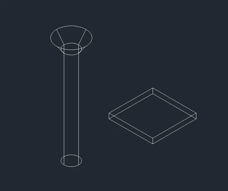
2. Select the Rectangle tool and draw the rectangle with the dimension of 4'6"×4'6"
3. Select the Extrude tool and Extrude the rectangle into the +Z direction at a height of 6" as shown in the figure below
Step 8:
1. Go to the Top view again using the UCS icon
2. Select the Extruded rectangle and move it into the Extruded circle at the center
3. Go to the default 3D view and move the Extruded rectangle from the bottom to the top at a distance of 10'
Step 9:
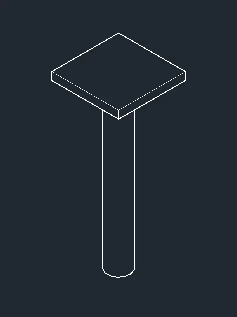
1. After moving the Extruded rectangle, go to the default 3D view
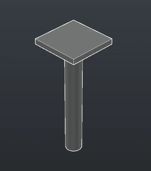
2. Change the viewing style model from the 2D wireframe to the Hidden
2. Now we can see the dropped color with the panel as shown in the figure below
RESULT:
The 3D model of the Drop column with panel has been sketched successfully as per the drawing
 \
\
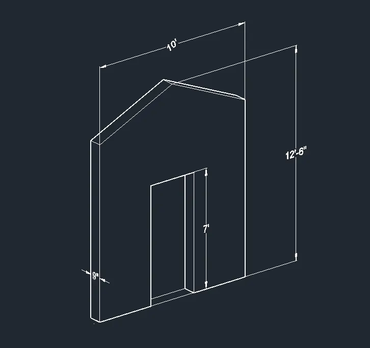
5. Create the 3d model of a wall as shown in Figure. Consider wall thickness as 9”.
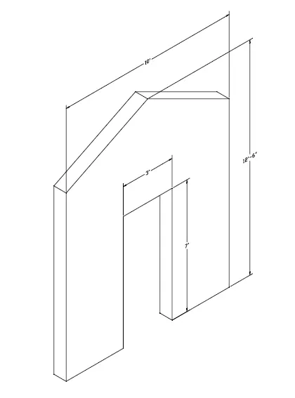
AIM:
To create the 3D model of a wall with the thickness of 9" as per the given drawing
INTRODUCTION:
Walls are constructed in different forms and of various materials to serve several functions. Exterior walls protect the building interior from external environmental effects such as heat and cold, sunlight, ultraviolet radiation, rain and snow, and sound while containing desirable interior environmental conditions. Walls are also designed to provide resistance to the passage of fire for some defined period, such as a one-hour wall. Walls often contain doors and windows, which provide for controlled passage of environmental factors and people through the wall line.
Polysolids are like 3D polylines that come with thickness. You can use them to quickly create walls based on a 2D floor plan. The result is a swept solid. You can also draw poly solids without a 2D floor plan, by just specifying points, but here I use existing objects as a basis. Follow these steps:
- Draw the 2D floor plan with lines or polylines. Use architectural units. You should be in the 3D Modeling workspace.
- Create a new layer for the walls and make it current.
- Set a view that will let you see the 3D walls. For example, display the View toolbar and choose SE Isometric. In 2009, choose Home tab> View panel> View drop-down list> SE Isometric.
COMMANDS USED:
1. Units
2. Limits
3. Rectangle
4. Line
5. Offset
6. Extrude
7. Move
8. Join
9. Trim
10. Union
PROCEDURE:
Step 1:
1. Open the Autocad software from the desktop
2. On the home page of the Autocad, Click on New drawing
3. Switch the model space into 3D modeling from the status bar
Step 2:
1. Type UN and set the units as Engineering and precision as 0' 0"
2. Set the units as Inches in the insertion scale
3. Type Limits in the command box and set the Lower limit as 0,0 and Upper limit as 100',100'
4. Type Z enter for Zoom Enter and A Enter for Zoom all
Step 3:
1. Go to the Front view using the UCS icon at the top right corner
2. Select the Rectangle tool by typing REC or Rectangle in the command box
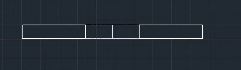
3. Draw a rectangle with the dimension of 10'×9"
4. Select the Line tool and draw the line at the center of the rectangle to cut into two parts
5. Select the Offset tool and offset the line on each side with an offset distance of 1'6" as shown in the figure below
Step 4:
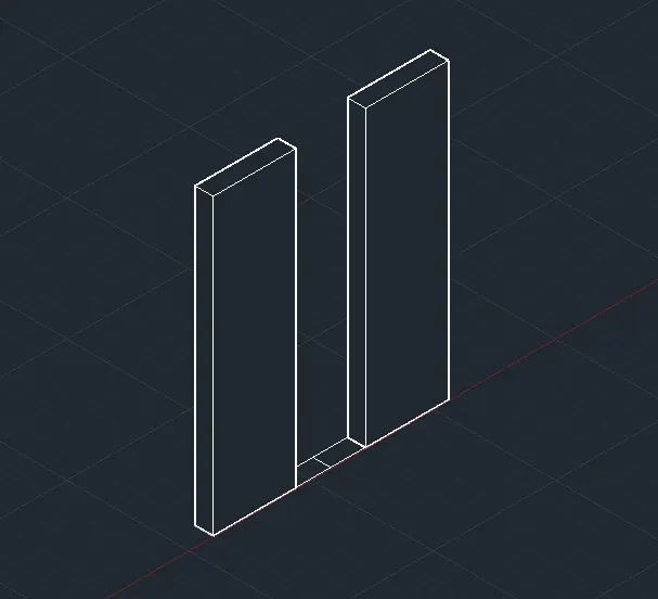
1. Select the Boundary tool by typing BO in the command box
2. Pick the Internal points of the rectangle to create the region except the door opening
3. Select the Extrude tool and Extrude it in +Z direction with a height of 12'6" as shown in the figure below
Step 5:
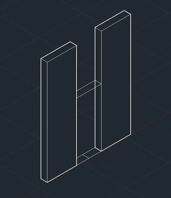
1. Select the Rectangle tool again and draw a rectangle at the door opening
2. Select the Move tool and move the rectangle in an upwards direction at a distance of 7' from the bottom
Step 6:
1. Go to the Front view using the UCS icon at the top right corner
2. Type UCS in the command box to provide X and Y Plane at the front view
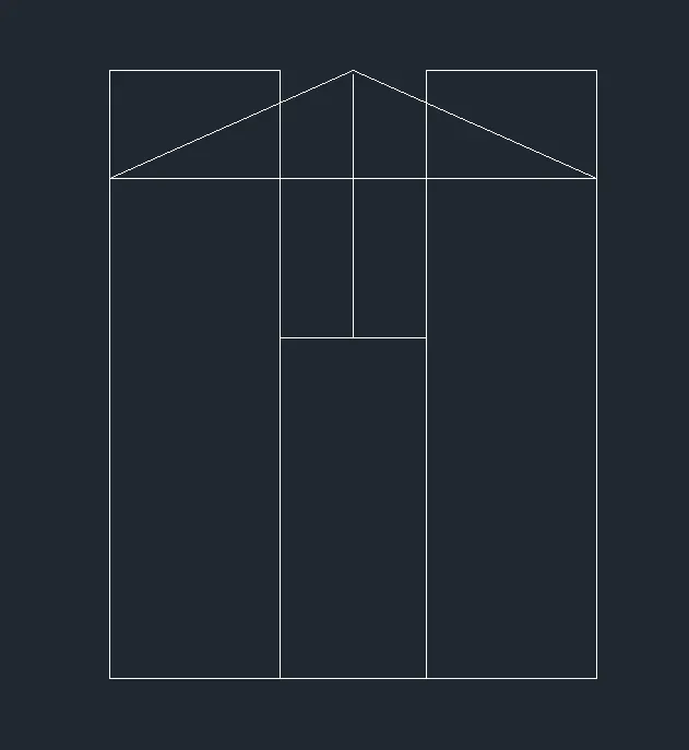
3. By using the Line command, draw a Triangle at the top of the section as shown in the figure below
4. Join the lines by using the Join command
5. By using the Trim command, Trim the unnecessary lines as shown in the figure below
Step 7:
1. Select the Extrude tool and Extrude the Triangle section into the +Y direction at a distance of 9"
2. Adjust the Extruded portion of the Triangle using grips to fit into the wall
3. Select the Rectangle of the door opening and Extrude it into the top surface
4. Select the Union command in the ribbon tab or by typing Union in the command box
5. Select the Extruded portions and press Enter to create a union section of the wall
6. Give dimensions using the DimLinear Command as per the drawing
RESULT:
The 3D model of the wall with a thickness of 9" has been sketched successfully as per the drawing