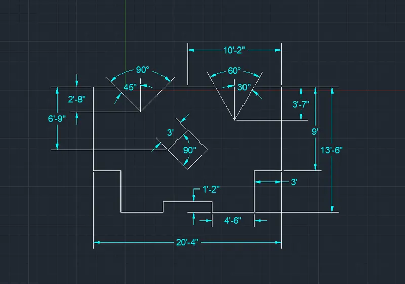
Drafting of various geometries using Chamfer, Fillet tool in AutoCad
AIM:
To draw the geometric Sketches by using various tools
INTRODUCTION:
AutoCAD offers various tools to perform different tasks. The various tools which are used for drafting are discussed in this project
PROCEDURE:
Sketching Figure 1:
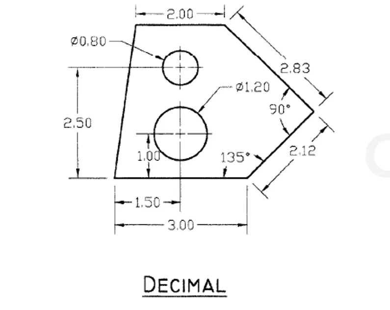
Commands used:
1. Line
2. XLine
3. Offset
4. Circle
5. Erase
6. Dimension
Step 1:
1. Select the Line Command by typing L or Line in Command box and press enter
2. Specify starting point of the line as 1,1
3. Now we specify the next points of the line using the Relative Polar Coordinates System
4. Specify the next point of the line as @3.0<0
5. Specify the next point of the line as @2.12<45
6. Specify the next point of the line as @2.83<135
7. Specify the next point of the line as @2.0<180
8. Then Click 'C' in the command box to close the line command
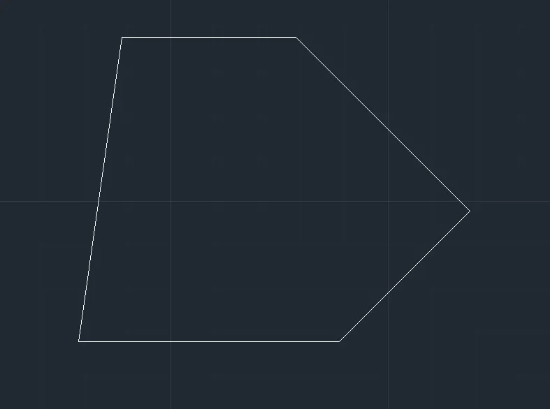
Step 2:
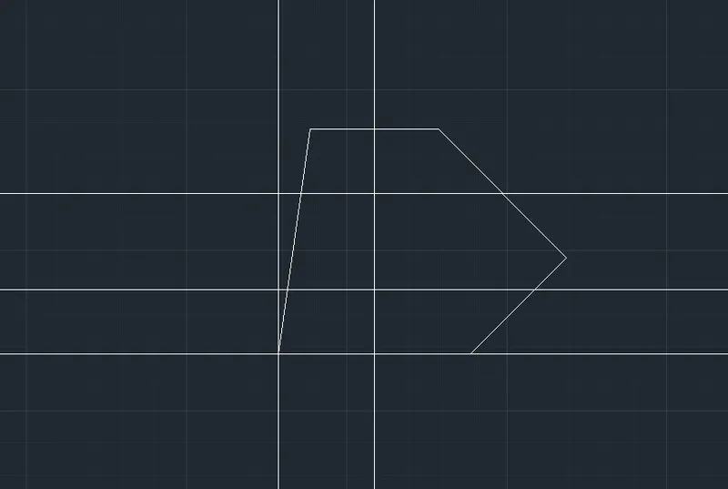
1. By using reference line, we have to draw offset lines by Specific distance
2. Select the XLine tool by typing XL or XLine in the Command box
3. Draw the horizontal and vertical lines at the start point as shown in the below figure
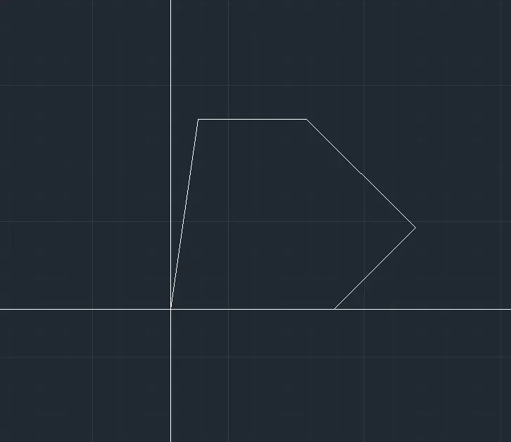
Step 3:
1. Select the Offest tool by typing 'O' or 'Offset' in the command box
2. Specify offset distance as 1.50
3. Select the Vertical reference line and offset the line to +X Direction
4. Again select the offset and specify offset distance as 1.00
5. Now select the Horizontal reference line and offset the line to +Y Direction as shown in the below figure
Step 4:
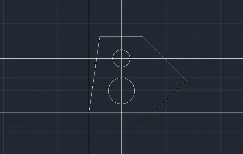
1. Select Circle by typing 'C' or 'Circle' in the command box
2. Specify the center point of the circle (i.e., the intersection of horizontal and vertical offest lines)
3. Select D for diameter in the command box and specify the diameter as 1.20
4. Do the same procedure for another circle by specifying the diameter as 0.80 and pressing escape to close the command
Step 5:
1. Select Erase tool by typing 'Erase' in the command box
2. Now erase the reference lines that we drawn earlier
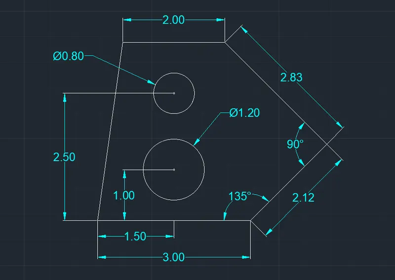
3. Give dimensions as per the drawing using the 'Dimension' command
RESULT:
Sketching Figure 2:
Command used:
1. Units
2. Line
3. Dimension
Step 1:
1. Open the Drawing Units dialog box by typing 'UN' or "Units" in the command box
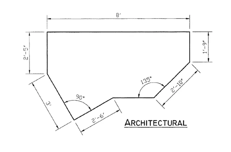
2. Set the Length type as Architectural and Precision as 0'-0 1/4" and click ok
3. Now select the Line Command by typing 'L' or 'Line' in the Command box and pressing enter
4. Specify starting point of the as 5,5
5. Now we specify the next points of the line using the Relative Polar Coordinates System
6. Specify the next point of the line as @8'<0
7. Specify the next point of the line as @1'9"<270
8. Specify the next point of the line as @2'10"<225 and Press 'Esc' to cancel the line command
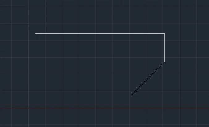
Step 2:
1. Select the Line Command by typing 'L' or 'Line' in the Command box and press enter
2. Specify the starting point of the line as 5,5
3. Specify the next point of the line as @2'5"<270
4. Specify the next point of the line as @3'<300
5. Specify the next point of the line as @2'6"<30
6. Now join the line that we left by clicking on that point.
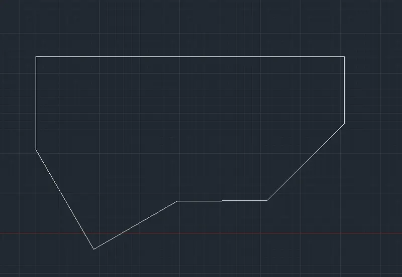
Step 3:
1. Give dimensions as per the drawing using the 'Dimension' command
RESULT:
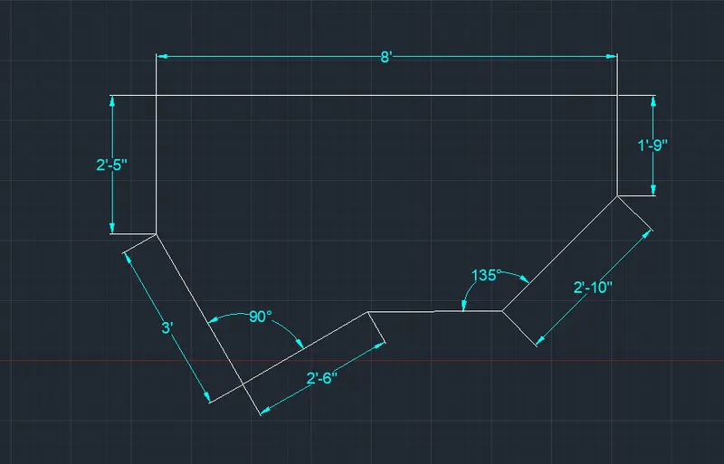
Sketching Figure 3:
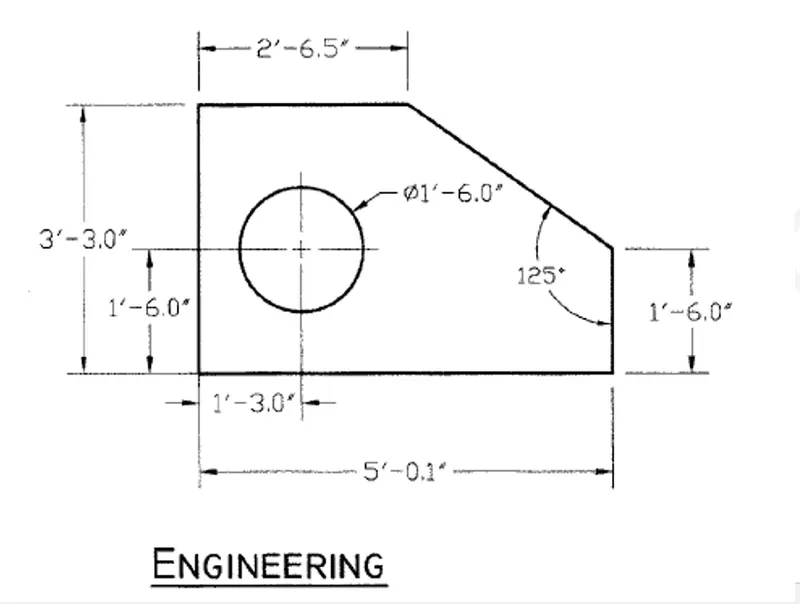
Commands used:
1. Units
2. Line
3. Offset
4. Circle
5. Erase
6. Dimension
Step 1:
1. Open the Drawing Units dialog box by typing 'UN' or "Units" in the command box
2. Set the Length type as Engineering and Precision as 0'-0.0" and click ok
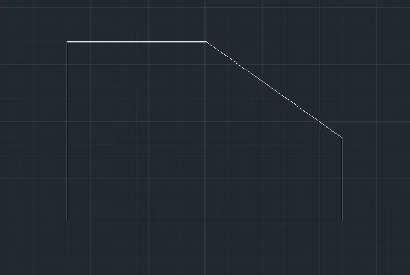
3. Now select the Line Command by typing 'L' or 'Line' in the Command box and pressing enter
4. Specify starting point of the line randomly by clicking the cursor on the screen
3. Now we specify the next points of the line using the Relative Polar Coordinates System
4. Specify the next point of the line as @2'6.5"<180
5. Specify the next point of the line as @3'3.0"<270
6. Specify the next point of the line as @5'0.1"<0
7. Specify the next point of the line as @1'6.0"<90
8. Then Click 'C' in the command box to close the line command
Step 2:
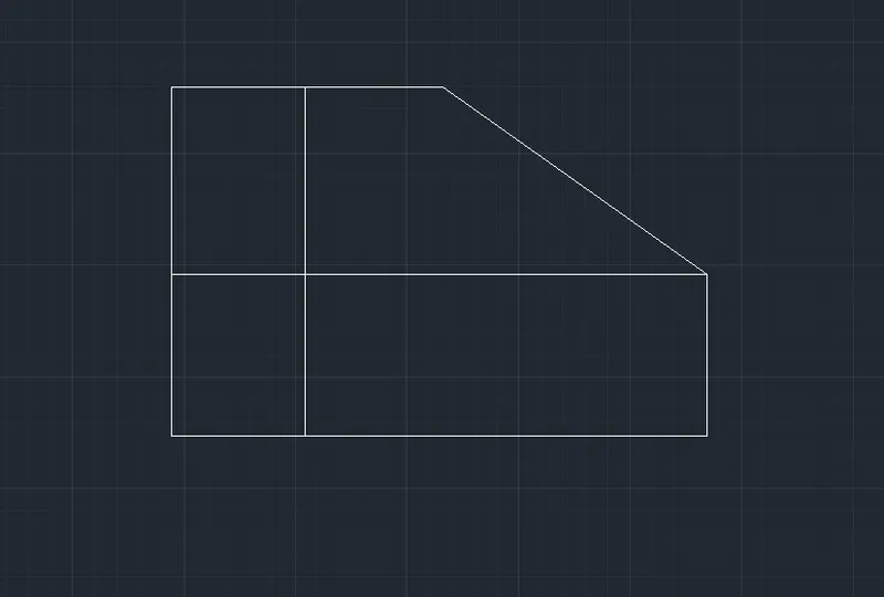
1. Select the Offest tool by typing 'O' or 'Offset' in the command box
2. Specify offset distance as 1'3.0"
3. Select the bottom line and offset the line to +X Direction
4. Again select the offset and specify the offset distance as 1'6.0"
5. Now select the left line and offset the line to +Y Direction as shown in the below figure
Step 3:
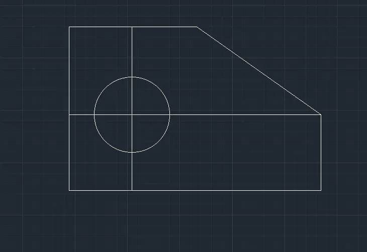
1. Select Circle by typing 'C' or 'Circle' in the command box
2. Specify the center point of the circle (i.e., the intersection of horizontal and vertical offset lines)
3. Select D for diameter in the command box and specify the diameter as 1'6.0"
Step 4:
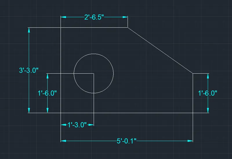
1. Select Erase tool by typing 'Erase' in the command box
2. Now erase the offset lines that we drawn earlier
2. Now give dimensions as per the drawing using the Dimension command
RESULT:
Sketching Figure 4:
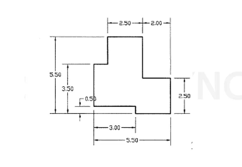
Commands Used:
1. Units
2. Line
3. Dimension
Step 1:
1. Open the Drawing Units dialog box by typing 'UN' or "Units" in the command box
2. Set the Length type as Decimal and Precision as 0.00 and click ok
3. Now select the Line Command by typing 'L' or 'Line' in the Command box and pressing enter
4. Specify starting point of the line randomly by clicking the cursor on the screen
5. Specify next point of the line as 3.0, pointing cursor towards +X direction
6. Specify next point of the line as 0.5, pointing cursor towards -Y direction
7. Specify next point of the line as 2.5, pointing cursor towards +X direction
8. Specify next point of the line as 2.5, pointing cursor towards +Y direction
9. Specify next point of the line as 2.0, pointing cursor towards -X direction
10. Specify next point of the line as 3.0, pointing cursor towards +Y direction
11. Specify next point of the line as 2.5, pointing cursor towards -X direction
12. Specify next point of the line as 2.0, pointing cursor towards -Y direction
13. Specify next point of the line as 1.0, pointing cursor towards -X direction
14. Specify next point of the line as 3.0, pointing cursor towards -Y direction
15. Press 'Esc' to cancel the line command
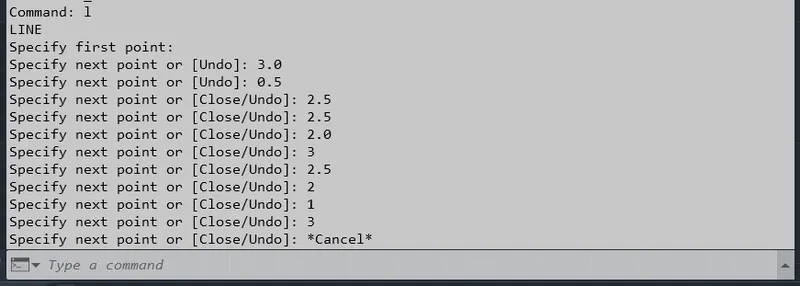
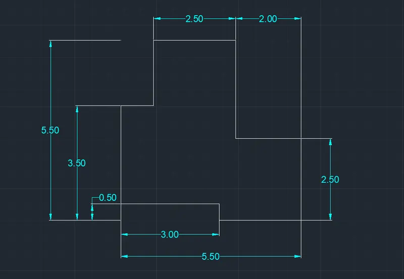
Step 2:
1. Give dimensions as per the drawing using the 'Dimension' command
RESULT:
Sketching Figure 5:
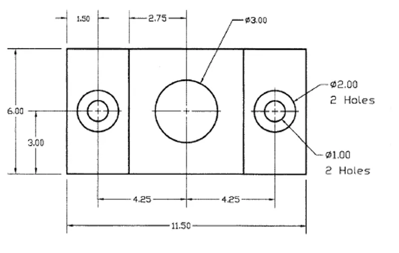
Commands Used:
1. Units
2. Line
3. Offset
4. Circle
5. Erase
6. Dimension
Step 1:
1. Open the Drawing Units dialog box by typing 'UN' or 'Units' in the command box
2. Set the Length type as Decimal and Precision as 0.00 and click ok
3. Now select the Line Command by typing 'L' or 'Line' in the Command box and pressing enter
4. Specify starting point of the line randomly by clicking the cursor on the screen
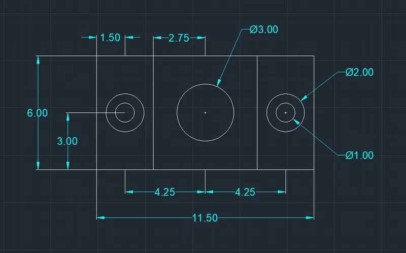
5. Specify next point of the line as 11.50, pointing cursor towards +X direction
6. Specify next point of the line as 6.0, pointing cursor towards +Y direction
7. Specify next point of the line as 11.50, pointing cursor towards -X direction
8. Specify next point of the line as 6.0, pointing cursor towards -Y direction
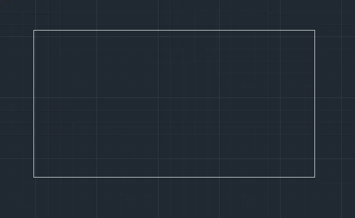
Step 2:
1. Select the Offest tool by typing 'O' or 'Offset' in the command box
2. Specify offset distance as 3.0
3. Select the corner left line and offset the line to +X Direction
4. Now select the corner right line and offset the line to -Y Direction as shown in the below figure
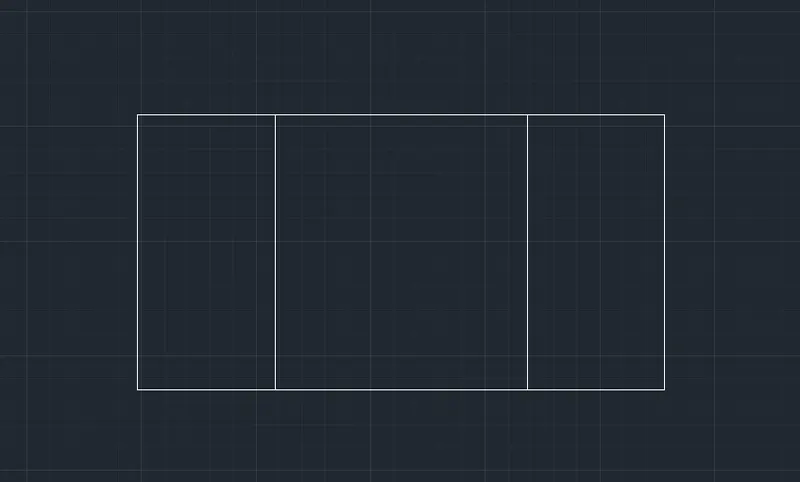
Step 3:
1. Select the Offest tool by typing 'O' or 'Offset' in the command box
2. Specify offset distance as 1.50
3. Select the corner left line and offset the line to +X Direction
4. Again select the offset tool and specify the offset distance as 5.75
5. Now select the corner left line again and offset the line to +X Direction as shown in the below figure
6. Again select the offset tool and specify the offset distance as 1.50
7. Now select the corner right line and offset the line to -X Direction as shown in the below figure
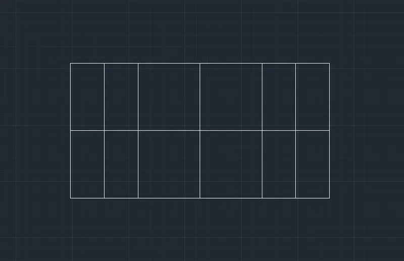
Step 4:
1. Select Circle by typing 'C' or 'Circle' in the command box
2. Specify the center point of the circle (i.e., the intersection of horizontal and vertical left offset lines)
3. Select D for diameter in the command box and specify the diameter as 2.0 and 1.0 respectively to draw 2 circles at the same center point
4. Select Circle by typing 'C' or 'Circle' in the command box
6. Specify the center point of the circle (i.e., the intersection of horizontal and vertical middle section offset lines)
7. Select D for diameter in the command box and specify the diameter as 3.0
8. Select Circle by typing 'C' or 'Circle' in the command box
9. Specify the center point of the circle (i.e., the intersection of horizontal and vertical right section offset lines)
10. Select D for diameter in the command box and specify the diameter as 2.0 and 1.0 respectively to draw 2 circles at the same center point
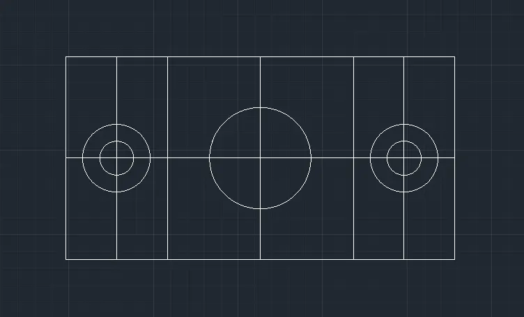
Step 5:
1. Select Erase tool by typing 'Erase' in the command box
2. Now erase offest lines that we drawn earlier for reference
3. Give dimensions as per the drawing using the 'Dimension' command
RESULT:
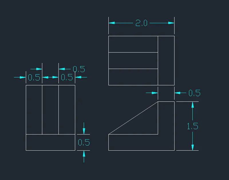
Sketching Figure 6:
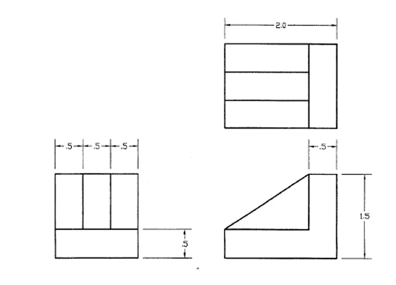
Commands used:
1. Line
2. Offset
3. Rotate
4. Dimension
Step 1:
1. Open the Drawing Units dialog box by typing 'UN' or 'Units' in the command box
2. Set the Length type as Decimal and Precision as 0.00 and click ok
3. Now select the Line Command by typing 'L' or 'Line' in the Command box and pressing enter
4. Specify starting point of the line randomly by clicking the cursor on the screen
5. Specify next point of the line as 2.0, pointing cursor towards +X direction
6. Specify next point of the line as 1.5, pointing cursor towards +Y direction
7. Specify next point of the line as 2.0, pointing cursor towards -X direction
8. Specify next point of the line as 1.5, pointing cursor towards -Y direction

Step 2:
1. Select the Offest tool by typing 'O' or 'Offset' in the command box
2. Specify offset distance as 0.5
3. Select the corner right line and offset the line to -X Direction
4. Now select the bottom line and offset the line to +Y Direction for 3 segments as shown in the below figure
5. Select the Trim tool by typing 'T' or 'Trim' in the command box and trim the unnecessary extra lines

Step 3:
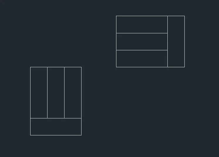
1. Select Rotate tool by typing 'RO' or 'Rotate' in the command box
2. Select the whole geometric section and specify a base point to rotate
3. Rotate the section 90° at clockwise direction as shown in the figure below
Step 4:
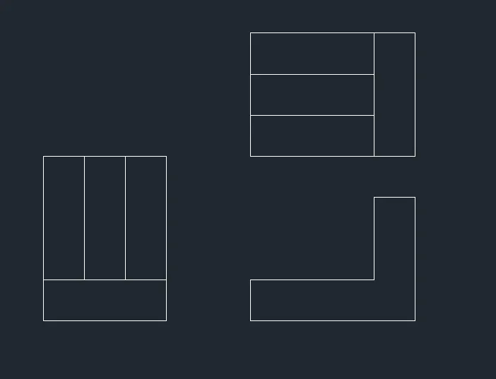
1. Select the Line Command by typing 'L' or 'Line' in the Command box and press enter
2. Specify starting point of the line randomly by clicking the cursor on the screen
3. Specify next point of the line as 2.0, pointing cursor towards +X direction
4. Specify next point of the line as 1.5, pointing cursor towards +Y direction
5. Specify next point of the line as 0.5, pointing cursor towards -X direction
6. Specify next point of the line as 1.0, pointing cursor towards -Y direction
7. Specify next point of the line as 1.5, pointing cursor towards -X direction
8. Then Click 'C' in the command box to close the line command
Step 5:
1. Join the slopped line from start point to endpoint as shown below
2. Give dimensions as per the drawing using the 'Dimension' command
RESULT:
Sketching Figure 7:
Commands Used:
1. Line
2. Offset
3. Rectangle
4. Copy
5. Arc
6. Circle
7. Xline
8. Fillet
9. Trim
10. Dimension
Step 1:
1. Select the Line Command by typing 'L' or 'Line' in the Command box and press enter
2. Specify starting point of the line randomly by clicking the cursor on the screen
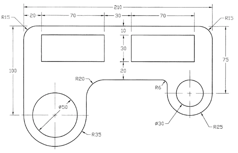
3. Specify next point of the line as 70, pointing cursor towards -X direction
4. Specify next point of the line as 100, pointing cursor towards +Y direction
5. Specify next point of the line as 210, pointing cursor towards +X direction
6. Specify next point of the line as 75, pointing cursor towards -Y direction
7. Specify next point of the line as 50, pointing cursor towards -X direction
8. Then Press 'Esc' to cancel the Line Command

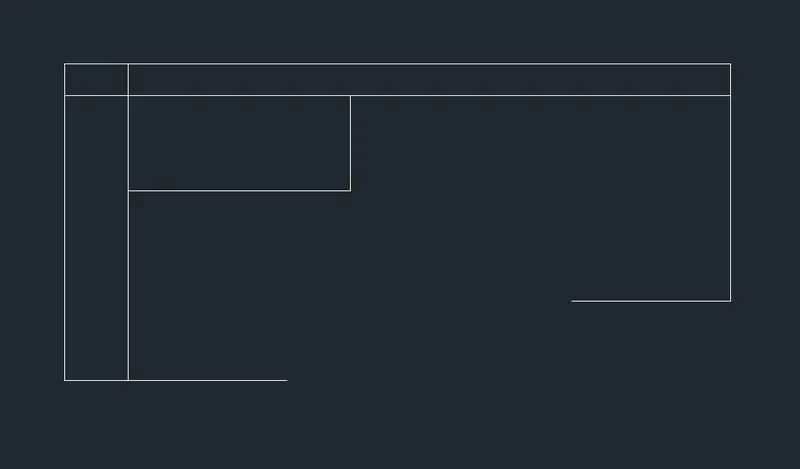
Step 2:
1. Select the Offest tool by typing 'O' or 'Offset' in the command box
2. Specify offset distance as 20
3. Select the Vertical left line and offset the line to +X Direction
4. Again select the offset and specify offset distance as 10
5. Now select the Horizontal top line and offset the line to -Y Direction as shown in the below figure
6. Select Rectangle by typing 'REC' or 'Rectangle' in the Command box
7. Specify the first point (i.e. the intersection of horizontal and vertical offset lines)
8. Specify length and width of rectangle as @70,-30
Step 3:
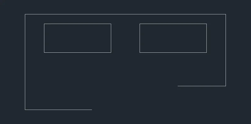
1. Select the Copy tool by typing 'CO' or 'COPY' in the Command box
2. Select the rectangle and specify the base point as the top corner point of the rectangle (i.e. the intersection of horizontal and vertical offset lines)
3. Specify copy distance as 100 and press Enter
4. Select Erase tool by typing 'Erase' in the command box
5. Now Erase the both Horizontal and Vertical offset lines
Step 4:
1. Select Arc by typing 'A' or 'ARC' in the command box
2. Specify start and endpoint of arc as shown in the figure below
3. Specify radius of the arc as 35
4. Similarly do the same procedure for another semi Arc by specifying the radius of the arc as 25 as shown in the figure below
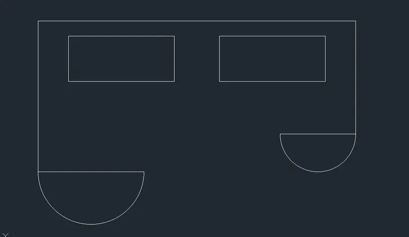
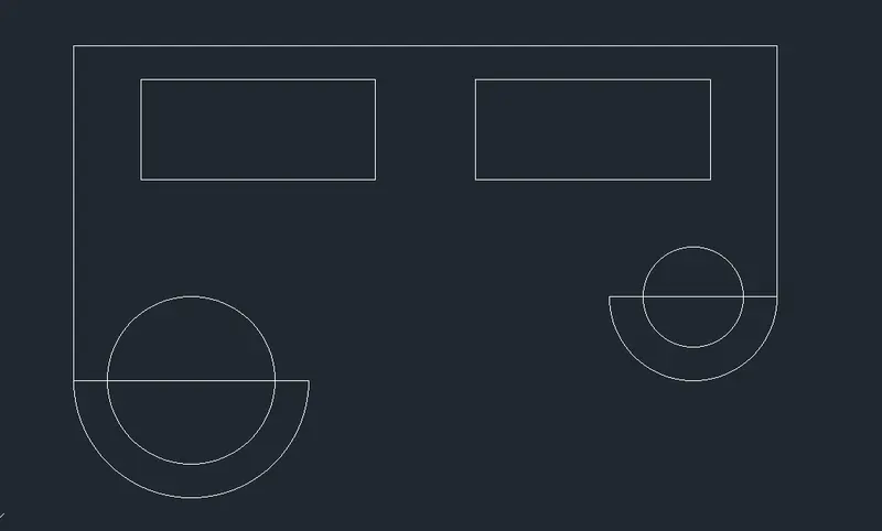
Step 5:
1. Select Circle by typing 'C' or 'Circle' in the command box
2. Specify the center point of the circle (i.e., the center of the below line that we used for reference to create an arc)
3. Select D for diameter in the command box and specify the diameter as 50
4. Do the same procedure for another circle by specifying the diameter as 20 and pressing escape to close the command
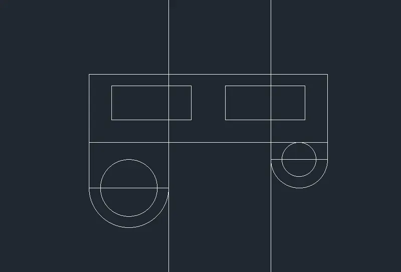
Step 6:
1. Select the Offest tool by typing 'O' or 'Offset' in the command box
2. Specify offset distance as 60
3. Select the top Horizontal line and offset the line to -Y Direction as shown in the figure below
4. Select Reference line by typing XL or XLINE in the command box
5. Now draw the reference lines as shown in the figure below
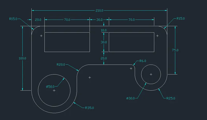
Step 7:
1. Select the Fillet tool by typing 'F' or 'Fillet' in the command box
2. Select the Fillet radius as 15
3. Select the lines that we want to do fillet as shown in the figure below
4. Select the Fillet tool again and now give radius as 20
5. Select the lines that we want to do fillet as shown in the figure below
6. Select the Fillet tool again and now give radius as 6
7. Select the lines that we want to do fillet as shown in the figure below

Step 8:
1. Select the Trim tool by typing 'T' or 'Trim' in the command box
2. Trim the unnecessary lines
3. Give dimensions as per the drawing using the 'Dimension' command
RESULT:
Sketching Figure 8:
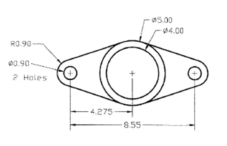
Commands Used:
1. Units
2. Line
3. Offset
4. Circle
5. Arc
6. Erase
7. Dimension
Step by Step Procedure:
Step 1:
1. Open the Drawing Units dialog box by typing 'UN' or "Units" in the command box
2. Set the Length type as Decimal and Precision as 0.00 and click ok
3. Now select the Line Command by typing 'L' or 'Line' in the Command box and pressing enter
4. Specify starting point of the line randomly by clicking the cursor on the screen
5. Specify next point of the line as 8.55, pointing cursor towards +X direction
6. Select the Offest tool by typing 'O' or 'Offset' in the command box
2. Specify offset distance as 0.9
3. Select the top Horizontal line and offset the line to both +Y and -Y Direction as shown in the figure below

Step 2:
1. Select Circle by typing 'C' or 'Circle' in the command box
2. Specify the center point of the circle as the center of the line that we drawn earlier
3. Select D for diameter in the command box and specify the diameter as 5.0
4. Do the same procedure for another circle by specifying the diameter as 4.0 and pressing escape to close the command

Step 3:
1. Select Circle by typing 'C' or 'Circle' in the command box
2. Specify the center point of the circle as the first point that we drawn earlier
3. Select D for diameter in the command box and specify the diameter as 0.90
4. Do the same procedure for another circle on the right-hand side by specifying the diameter as 0.90 and pressing escape to close the command
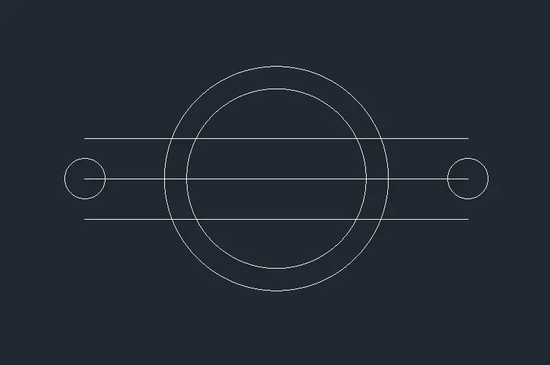
Step 4:
1. Select the Arc tool by typing 'A' or 'ARC' in the command box
2. Select Start, End, Radius option
3. Specify the start point of the arc as the first point of the top fillet line that we drawn earlier
4. Specify the endpoint of the arc as the first point of the bottom fillet line that we drawn earlier
5. Specify the radius of arc as 0.90 and press Enter
6. Do the same procedure for another arc on the right-hand side by specifying the radius of the arc as 0.90 as shown in the figure below
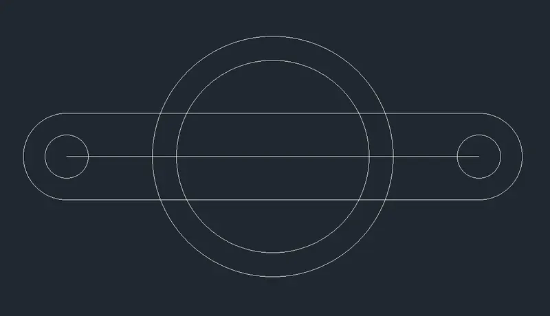
Step 5:
1. Select the Line Command by typing 'L' or 'Line' in the Command box and press enter
2. Join the line from the arc to the tangent of the circle
3. Do the same for the right-hand side also
4. Select Erase tool by typing 'Erase' in the command box
5. Erase the offset lines and unnecessary lines as shown in the figure below
RESULT:
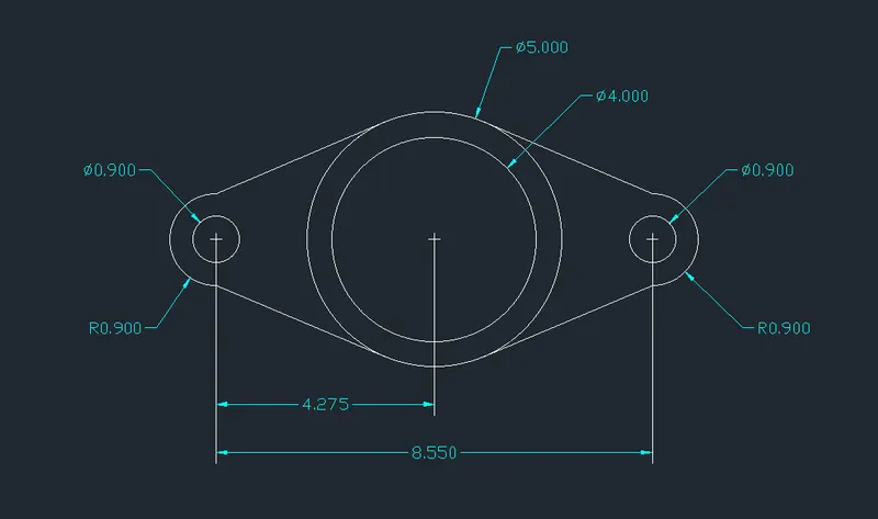
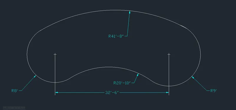
Sketching Figure 9:
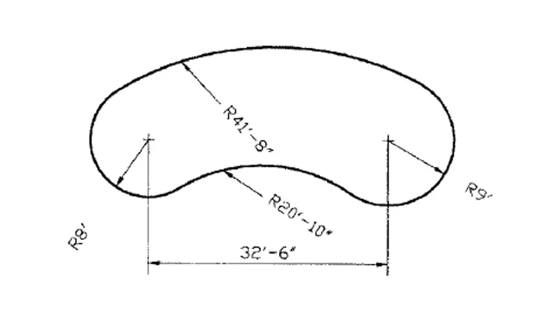
Commands Used:
1. Line
2. Circle
3. Fillet
4. Arc
5. Erase
6. Dimension
Step by Step Procedure:
Step 1:
1. Open the Drawing Units dialog box by typing 'UN' or "Units" in the command box
2. Set the Length type as Engineering and Precision as 0.0 and click ok
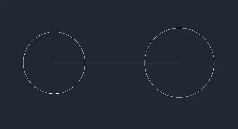
3. Now select the Line Command by typing 'L' or 'Line' in the Command box and pressing enter
4. Specify starting point of the line randomly by clicking the cursor on the screen
5. Specify next point of the line as 32'6", pointing cursor towards +X direction
6. Select Circle by typing 'C' or 'Circle' in the command box
7. Specify the center point of the circle as the first point of the line that we drawn earlier
8. Specify the radius as 8'
9. Do the same procedure for another circle on the right-hand side by specifying the radius as 9' and pressing escape to close the command
Step 2:
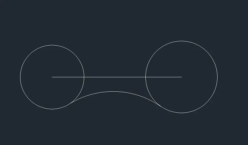
1. Select the Fillet tool by typing 'F' or 'FILLET' in the command box
2. Select radius option in that commands box
3. Now give the radius of the Fillet as 20'10"
4. Select the objects as a left circle and right circle and press Enter
Step 3:
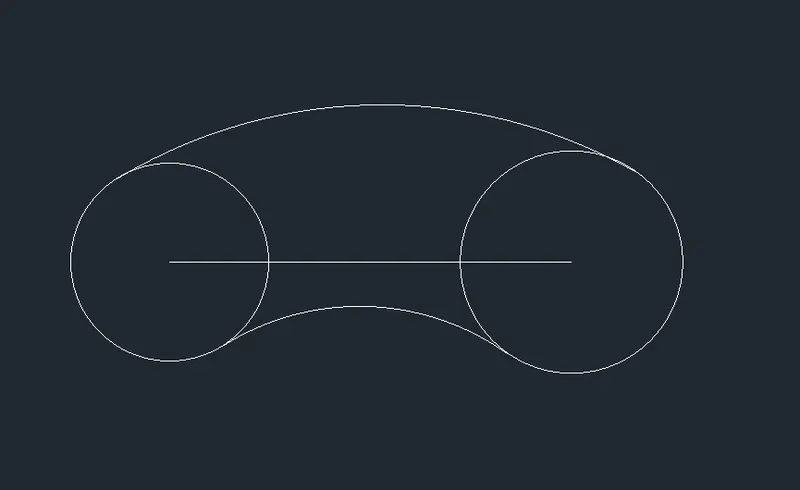
1. Select the Arc tool by typing 'A' or 'ARC' in the command box
2. Select Start, End, Radius option
3. Specify the start point of the arc as the left-hand side circle
4. Specify the endpoint of the arc as the right-hand side circle
5. Specify the radius of arc as 41'8" and press Enter
Step 4:
1. Select Erase tool by typing 'Erase' in the command box
2. Erase the line that we draw earlier for reference and erase unnecessary lines as shown in the figure below
3. Give dimensions as per the drawing using the 'Dimension' command
RESULT:
Sketching Figure 10:
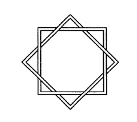
Commands Used:
1. Rectangle
2. Offset
3. Rotate
Step by Step Procedure:
Step 1:
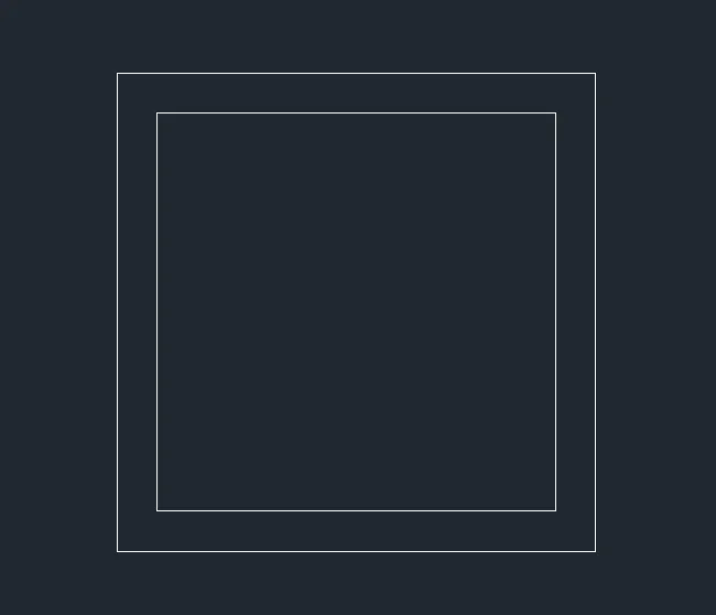
1. Select Rectangle by typing 'REC' or 'Rectangle' in the command box
2. Specify the start point of the rectangle randomly by clicking the cursor on the screen
3. Give Dimensions of the rectangle as Equal (i.e., length and width)

Step 2:
1. Select the Offset command by typing 'O' or 'Offest' in the command box
2. Give most off distance as greater than the previous rectangle and offset it through outside
Step 3:
1. Select Rotate command by typing 'RO' or 'Rotate' in the command box
2. Select the two rectangles as we have drawn
3. Specify the base point as the center of the rectangle
4. Select the Copy option in the command box
5. Now Specify the rotation angle as 45° and it will be rotated by 45° angle as shown in the figure below

Step 4:
1. Select the Trim tool by typing 'T' or 'TRIM' in the command box
2. Now trim the unnecessary extra lines as shown in the figure below
RESULT:

Sketching Figure 11:
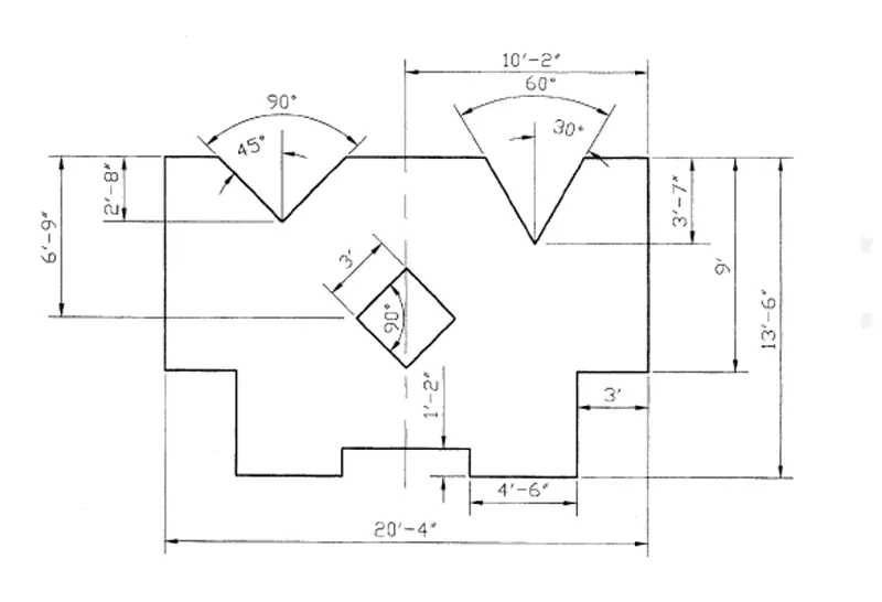
Commands Used:
1. Line
2. Mirror
3. Offset
4. Rectangle
5. Trim
6. Move
7. Rotate
8. Dimension
Step by Step Procedure:
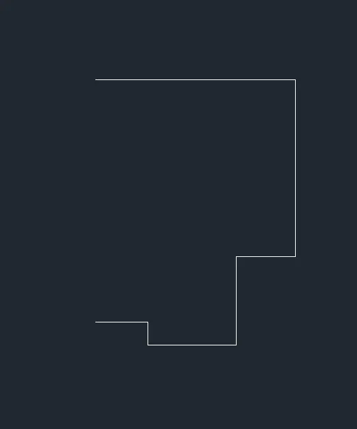
Step 1:
1. Select the Line Command by typing 'L' or 'Line' in the Command box and press enter
2. Specify starting point of the line randomly by clicking the cursor on the screen
3. Specify next point of the line as 10'2", pointing cursor towards +X direction
4. Specify next point of the line as 9', pointing cursor towards -Y direction
5. Specify next point of the line as 3', pointing cursor towards -X direction
6. Specify next point of the line as 4'6", pointing cursor towards -Y direction
Specify next point of the line as 4'6", pointing cursor towards -X direction
7. Specify next point of the line as 1'2", pointing cursor towards +X direction
8. Specify next point of the line as 2'8"', pointing cursor towards -X direction
9. Press 'Esc'to cancel the Line Command
Step 2:
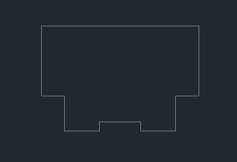
1. Select Mirror command by typing 'MI' or 'MIRROR'
2. Select the lines starting from the first line to the last line
3. Specify the base point as 1st point of the first line
4. Then mirror the whole geometric into -X direction
Step 3:
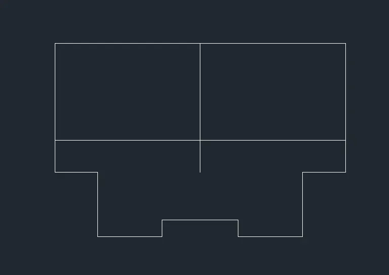
1. Select the Offest tool by typing 'O' or 'Offset' in the command box
2. Specify offset distance as 6'9" and 10'2"
3. Select the top Horizontal line and offset the line to -Y direction, similarly right vertical line to -X-direction respectively as shown in the figure below
Step 4:
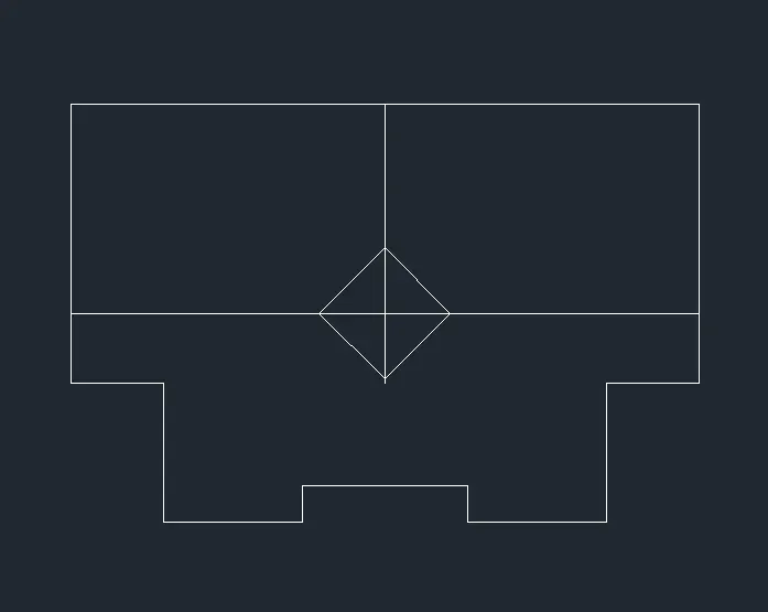
1. Select Rectangle by typing 'REC' or 'Rectangle' in the command box
2. Select the starting point of the rectangle (i.e., the intersection of horizontal and vertical offset lines)
3. Specify length and width of rectangle as 3'
4. Select the Move tool by typing 'M' or 'Move' in the command box
5. Specify the base point as the center of the rectangle and move through the intersection point of horizontal and vertical offset lines
6. Select Rotate tool by typing 'RO' or 'ROTATE' in the command box
7. Specify the base point as the center point of the rectangle
8. Specify the angle of rotation as 45°
Step 5:
1. Select the Offest tool by typing 'O' or 'Offset' in the command box
2. Specify offset distance as 6
2'8" and 3'7"
3. Select the top left Horizontal line and offset the line to -Y direction, similarly the right horizontal line to -Y direction respectively as shown in the figure below
4. Select the center of the previous offset line and draw the lines at 45° through the left side and 135° through the right side
5. Select the center of the previous offset line and draw the lines at 60° through the left side and 120° through the right side
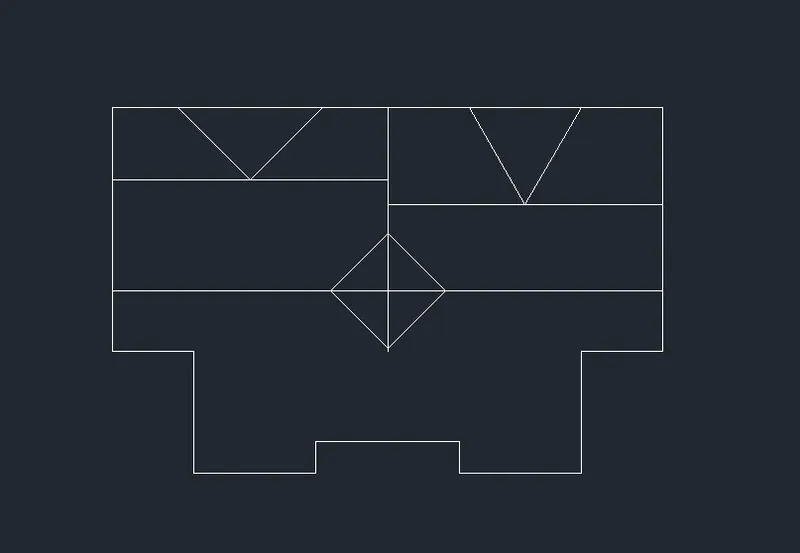
Step 6:
1. Select the Trim tool by typing 'TR' or 'TRIM' in the command box
2. Trim the unnecessary lines and erase the reference lines
3. Give dimensions as per the drawing using the 'Dimension' command
RESULT: