Creating Kitchen layout, Hatching of Architectural elements and sectional view of an Industrial Building in AutoCad
Creating Kitchen layout, Hatching of Architectural elements, and sectional view of an Industrial Building in AutoCad
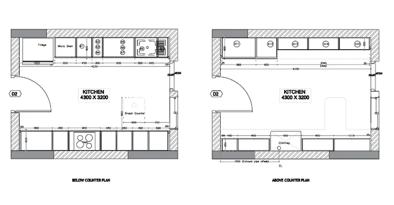
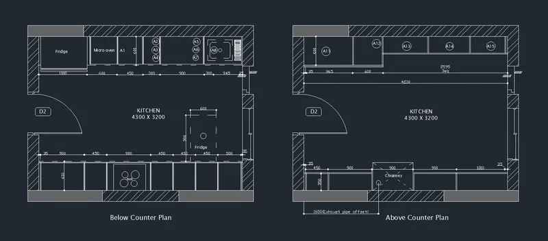
1. Create the layouts of the Kitchen and provide a hatches pattern as shown. Also, use blocks wherever required. Provide appropriate dimensions in the plan. Assume the size of doors, appliances, and others as per the standards.
AIM:
To create the layouts of the kitchen and provide hatch pattern, and appropriate dimensions as per the requirement
INTRODUCTION:
Kitchen Layout is the shape of arrangement of the kitchen cabinet and kitchen appliances, kitchen layout forms the structure and the design of our kitchen. The effectiveness of space utilize very much dependent on the kitchen layout, a suitable kitchen layout ensures the efficiency of space planning and kitchen workflow.
COMMANDS USED:
1. Units
2. Limits
3. Line
4. Rectangle
5. Circle
6. Arc
7. Offset
8. Trim
9. Move
10. Copy
11. Hatch
12. MText
13. DimLin
PROCEDURE:
Step 1:
1. Open the Autocad application and Type Qnew to open New drawing
2. In the startup dialog box set Metric as the default settings
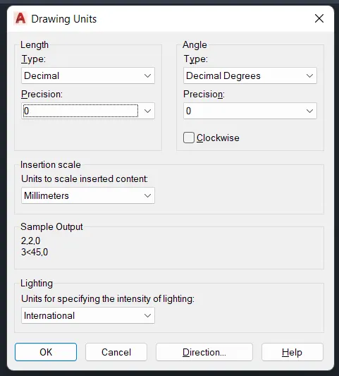
3. Type UN and set the units as Decimal and precision as 0.0
4. Set the units as Millimetres in the insertion scale
5. Type Limits in the command box and set the Lower limit as 0,0 and Upper limit as 10000,10000
6. Type Z enter for Zoom Enter and A Enter for Zoom all
Step 2:
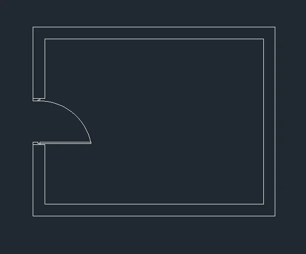
1. Select the Rectangle tool by typing REC or Rectangle in the command box
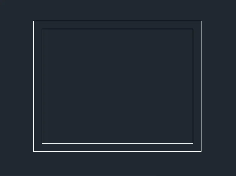
2. Draw the rectangle with the dimension of 4300 as length and 3200 as breadth
3. Select the Offset tool by typing O or Offset in the command box
4. Give the Offset distance as 230mm and Offset the previous rectangle through inside as shown in the figure below
Step 3:
1. Now we have to create the entrance for the door
2. Select the Offset tool by typing O or Offset in the command box
3. Give an offset distance of 900mm and create the entrance as shown in the figure below
4. By using Arc and Line tool, draw a door as shown in the figure below
Step 4:
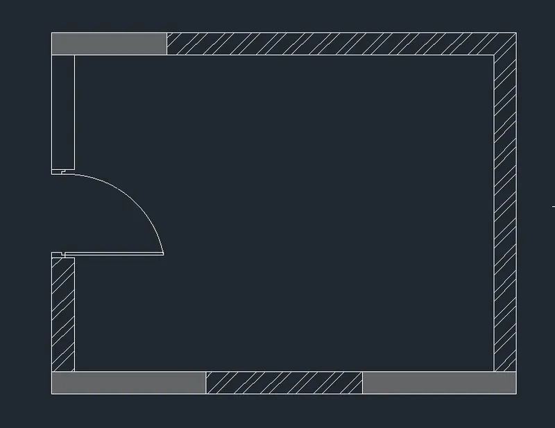
1. Now we have to sketch the appropriate hatch pattern for the wall
2. Select the Hatch tool by typing H or Hatch in the command box
3. Select the hatch pattern as solid and hatch color as grey
4. Pick the point inside the wall as shown in the figure below
5. Select the hatch pattern again as ANSI 132
6. Pick the point and give the hatch scale as per the requirement
Step 5:
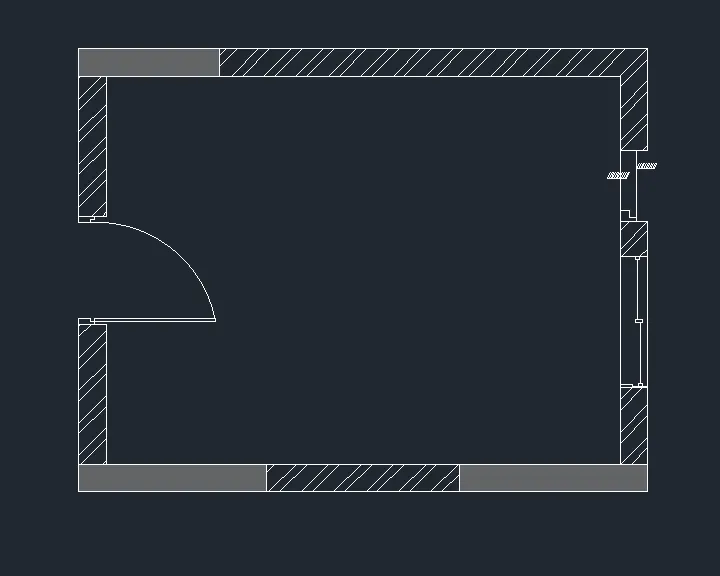
1. Now we have to showcase the window inside the wall
2. Select the Line tool by typing L or Line in the command box
3. Create the window with the help of the line tool and rectangle tool
4. Select the Trim tool by typing TR or Trim in the command box
5. Trim the unnecessary extra lines as shown in the figure below
Step 6:
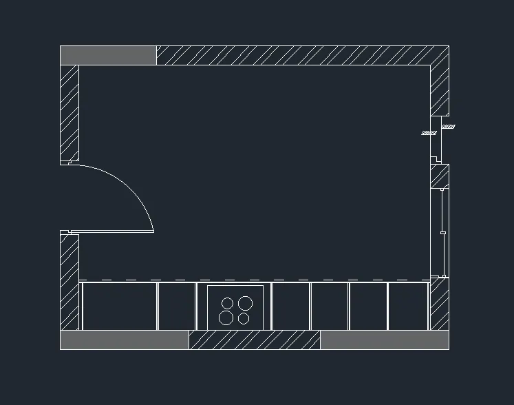
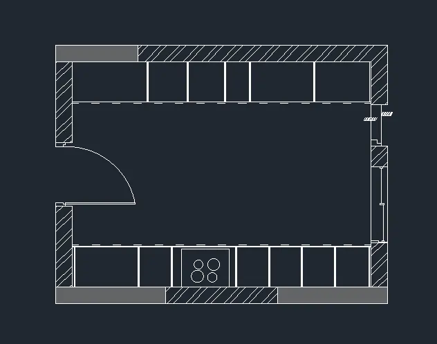
1. Select the Offset tool by typing O or Offset in the command box
2. Give offset distance as 600mm and offset the bottom inside line through the inside
3. Select the line and change the line type to ISO dash dash
4. Select the Offset tool again and give offset distance as 35, 900, 450, 900, 450, 450, 450, 500, 35 respectively
5. Offest the lines through inside one by one as shown in the figure below
6. Select the Circle tool by typing C or Circle in the command box
7. Draw four circles in the rectangle section as shown in the figure below
Step 7:
1. Select the Offset tool by typing O or Offset in the command box
2. Give offset distance as 600mm and offset the Too inside line through the inside portion
3. Select the line and change the line type to ISO dash dash
4. Select the Offset tool again and give offset distances like 35, 1000, 600, 450, 300, 900, 300, 945, and 35mm respectively
5. Offest the lines through inside one by one as shown in the figure below
Step 8:
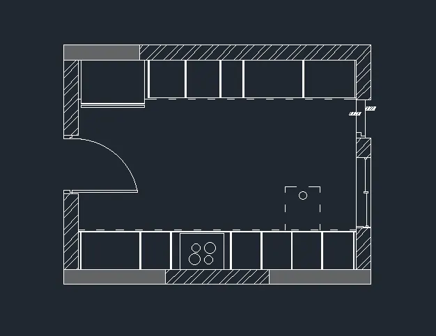
1. Now we have to sketch the snack counter below the portion
2. Select the Line tool by typing L or Line in the command box
3. Draw a vertical line upwards at a distance of 900mm from the Countertop as shown in the figure below
4. Continue the line command and draw a horizontal line at a distance of 600mm and close the line command
5. Draw a Circle of 100mm radius inside the snack counter portion as shown in the figure below
Step 9:
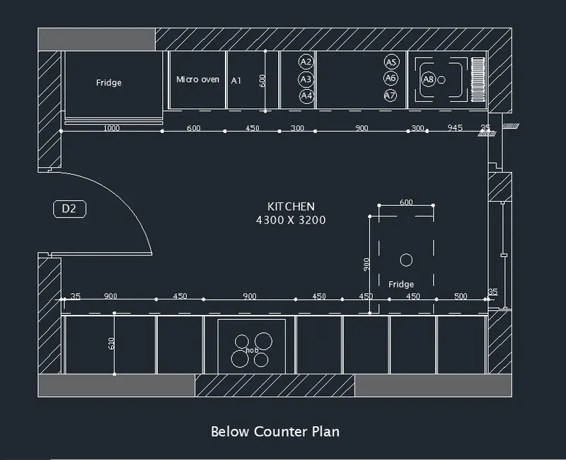
1. Enter DS in the command box to open the dimension style manager dialog
2. Modify the dimensions as per the requirement
3. Change the color of the dimension and extension line as per the requirement
4. Under the text option, Change the text height to 50mm
5. click ok, then click set current and close the dimension style manager dialog box
6. Give dimensions and text as per the drawing and requirement using the Mtext command and Dimension Command
Step 10:
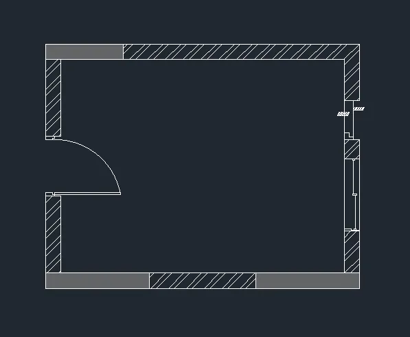
1. Select the Copy tool by typing CO or Copy in the command box
2. Copy the layout except for the components inside it
3. Move the copied layout to the desired location as shown in the figure below
Step 11:
1. Select the Offset tool by typing O or Offset in the command box
2. Give offset distance as 350mm and offset the bottom inside line through the inside portion
3. Select the line and change the line type to ISO dash dash
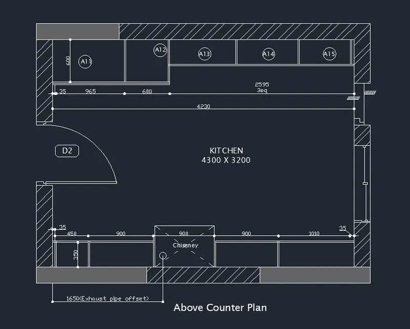
4. Select the Offset tool again and give offset distances like 35, 450, 900, 900, 900, 1010, and 35mm respectively
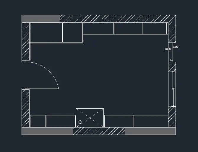
5. Offest the lines through inside one by one as shown in the figure below
6. Select the Offset tool by typing O or Offset in the command box
7. Give offset distance as 600mm and offset the Too inside line through the inside portion
8. Select the Offset tool again and give offset distances like 35, 945, 600, and 2595mm respectively
9. Offest the lines through inside one by one as shown in the figure below
10. Adjust the remaining components in the kitchen layout using the Trim tool and Extend tool
Step 12:
1. Enter DS in the command box to open the dimension style manager dialog
2. Modify the dimensions as per the requirement
3. Change the color of the dimension and extension line as per the requirement
4. Under the text option, Change the text height to 50mm
5. click ok, then click set current and close the dimension style manager dialog box
6. Give dimensions and text as per the drawing and requirement using the Mtext command and Dimension Command
RESULT:
The Kitchen Layouts have been created and provide appropriate hatch and dimensions successfully
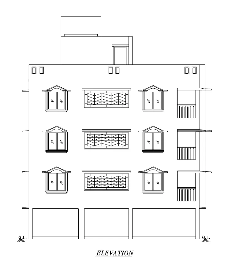
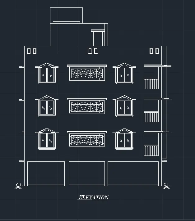
2. Create the elevation of the plan created in the Challenges 7 and apply proper hatch in the walls, doors, windows, and other architectural elements. Refer to the dimensions in Plans and sections in Challenges 7.
AIM:
To create the elevation of the floor plan created in challenge 7 and apply proper hatching to the doors windows and other architectural elements
INTRODUCTION:
An elevation drawing is an orthographic projection drawing that shows one side of the house. The purpose of an elevation drawing is to show the finished appearance of a given side of the house and furnish vertical height dimensions.
An elevation plan ordinarily includes the following:
• Identification of the specific side of the house that the elevation represents
• Grade lines
• Finished floor and ceiling levels
• Location of exterior wall corners
• Windows and doors
• Roof features
• Porches, decks, and patios
• Vertical dimensions of important features
• Material symbols
COMMANDS USED:
1. Units
2. Limits
3. Line
4. Rectangle
5. Offset
6. Copy
7. Hatch
8. Mtext
9. DimLin
10. Trim
PROCEDURE:
Step 1:
1. Open the Autocad application and Type Qnew to open New drawing
2. In the startup dialog box set Metric as the default settings
3. Type UN and set the units as Decimal and precision as 0.0
4. Set the units as Millimetres in the insertion scale
5. Type Limits in the command box and set the Lower limit as 0,0 and Upper limit as 10000,10000
6. Type Z enter for Zoom Enter and A Enter for Zoom all
Step 2:
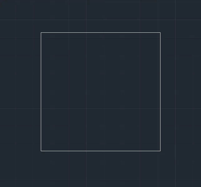
1. Select the Rectangle tool by typing REC or Rectangle in the command box
2. Specify the Length of the rectangle as 10000mm
3. Specify the Width of the rectangle as 8000mm
4. The Rectangle is been created as shown in the figure below
Step 3:
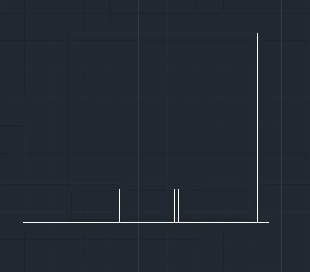
1. Select the Line tool by typing L or Line in the command box
2. Draw a line below the rectangle to show the ground level
3. Select the Rectangle tool and draw two rectangles of dimension 3000×2000mm inside the elevation
4. Draw another rectangle with the dimension of 5000×2000mm as shown in the figure below
Step 4:
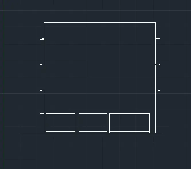
1. Select the Line command by typing L or Line in the command box
2. By using the line command Draw the lintel level at the each floor
3. Copy the lintels and move to the desired locations as shown in the figure below
Step 5:
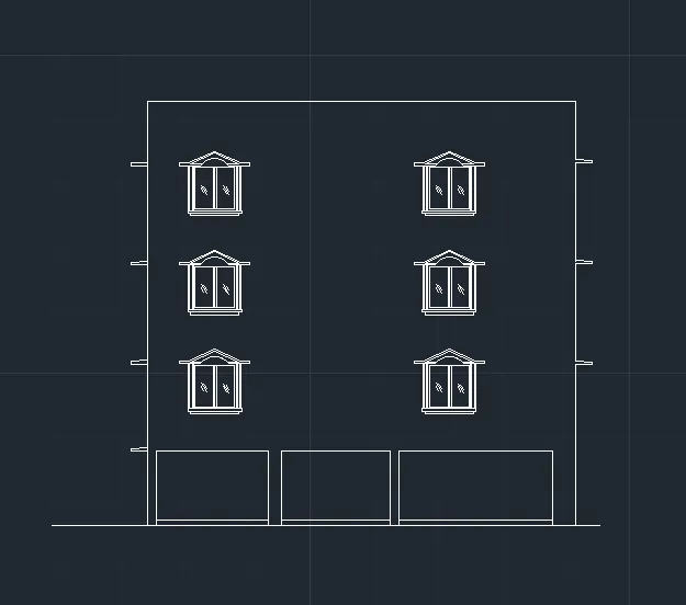
1. Now we have to draw the windows and paste them into desired locations
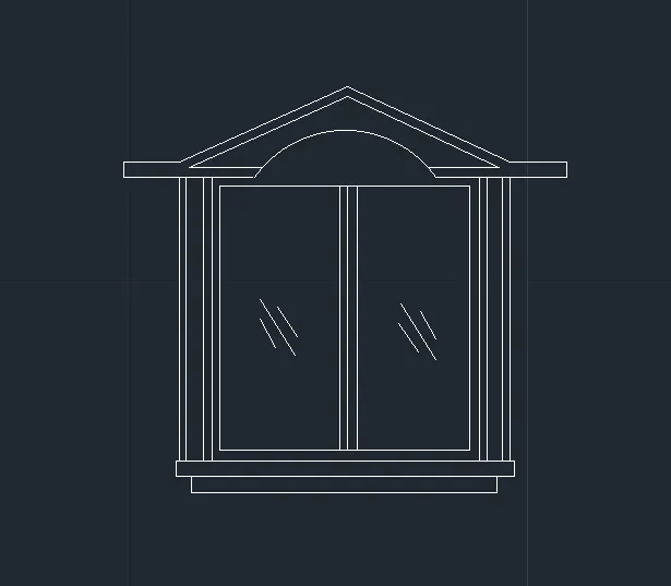
2. Select the Rectangle tool by typing REC or Rectangle in the command box
3. Draw a Rectangle with the dimension of 1000x1000mm
4. Select the Offset tool and give offset distances as 200, and 300mm respectively
5. Offset the rectangles through inside as shown in the figure below
6. By using the Line tool, sketch the other parts of the window
7. Provide glass panels shading on each side of the window with the help of a line tool
8. Sketch the base and top portion of the window as shown in the figure below
Step 6:
1. After creating the window, now we have to Copy the windows to the desired location
2. Select the Window that we created and copy it using the Copy tool
3. Paste the windows to each floor at the desired location as shown in the figure below
Step 7:
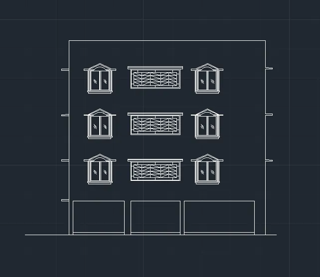
1. Now we have to create another wide window in the Elevation
2. Select the Rectangle tool and draw a window of dimension 4000×1000mm
3. Sketch the top portion of the windows with the help of the Line and Rectangle tool
4. By using the Hatch tool, hatch the interior portion of the window as shown in the figure below
5. Select the Copy tool by typing CO or Copy in the command box
6. Paste the windows to each floor at the desired locations as shown in the figure below
Step 8:
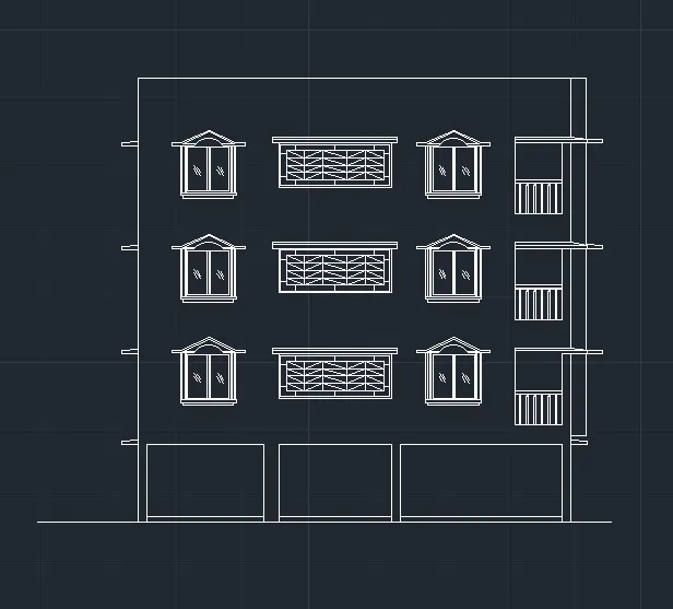
1. Select the Rectangle tool by typing REC or Rectangle in the command box
2. Draw a rectangle with the dimension of 1000×2000mm
3. Sketch the top portion using the Rectangle tool and Line tool
4. Select the Copy tool by typing CO or Copy in the command box
5. Paste the balcony section to each floor at the desired locations as shown in the figure below
Step 9:
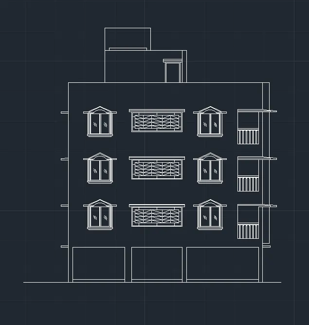
1. Now we have to create the top roof above the parapet wall
2. Select the Rectangle tool by typing REC or Rectangle in the command box
3. Draw a rectangle with the dimension of 5000×2500mm
4. Draw another rectangle above the previous one as shown in the figure below
5. Sketch the door entrance with the help of the Rectangle and Line tool
6. Select the Trim tool by typing TR or Trim in the command box
7. Trim the unnecessary lines as shown in the figure below
Step 10:
1. Enter DS in the command box to open the dimension style manager dialog
2. Modify the dimensions as per the requirement
3. Change the color of the dimension and extension line as per the requirement
4. Under the text option, Change the text height to 50mm
5. click ok, then click set current and close the dimension style manager dialog box
6. Give dimensions and text as per the drawing and requirement using the Mtext command and Dimension Command
RESULT:
The Elevation of the floor plan has been created successfully and added proper hatching to it.
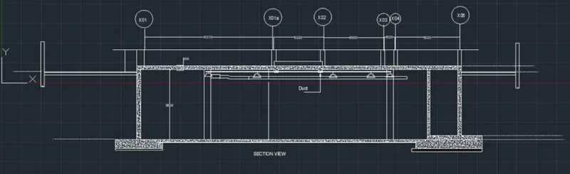
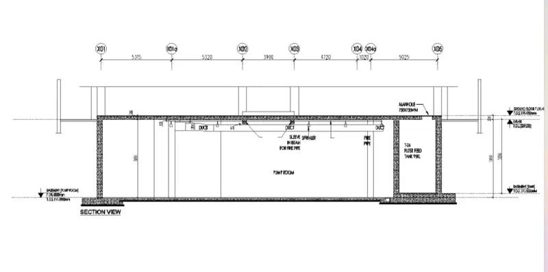
3. Create the section view of an industrial building as shown in Figure. Provide appropriate hatches and dimensions wherever required. Also, provide annotations to the drawing.
AIM:
To create the section view of industrial building and to provide appropriate hatches and dimensions as per requirement
INTRODUCTION:
A sectional view represents the part of an object remaining after a portion is assumed to have been cut and removed. The exposed cut surface is then indicated by section lines. Hidden features behind the cutting plane are omitted unless required for dimensioning or for the definition of the part.
A 'section drawing', 'section', or 'sectional drawing' shows a view of a structure as though it had been sliced in half or cut along another imaginary plane.
For buildings, this can be useful as it gives a view through the spaces and surrounding structures (typically across a vertical plane) that can reveal the relationships between the different parts of the buildings that might not be apparent on plan drawings. Plan drawings are a type of section, but they cut through the building on a horizontal rather than vertical plane.
COMMANDS USED:
1. Units
2. Limits
3. Line
4. Rectangle
5. Hatch
6. Trim
7. Mtext
8. Dim Linear
PROCEDURE:
Step 1:
1. Open the Autocad application and Type Qnew to open New drawing
2. In the startup dialog box set Metric as the default settings
3. Type UN and set the units as Decimal and precision as 0.0
4. Set the units as Millimetres in the insertion scale
5. Type Limits in the command box and set the Lower limit as 0,0 and Upper limit as 10000,10000
6. Type Z enter for Zoom Enter and A Enter for Zoom all
Step 2:
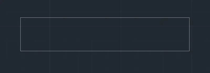
1. Select the Rectangle tool by typing REC or Rectangle in the command box
2. Specify the length of the rectangle as 5000mm and width as 2000mm
3. Draw a rectangle with the above dimensions as shown in the figure below
Step 3:
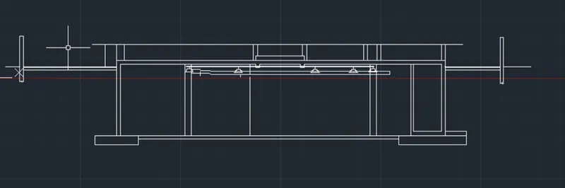
1. Select the Line tool by typing L or Line in the command box
2. Draw the lines connecting the rectangle to represent the section views
3. Select the Rectangle tool by typing REC or Rectangle in the command box
4. Specify the length of the rectangle as 2000mm and width as 500mm
5. Draw a rectangle below the hinges with the above dimensions as shown in the figure below
6. Select the Line tool again and sketch the other parts of the sectional view
7. Select the Trim tool and trim the unnecessary lines
Step 4:
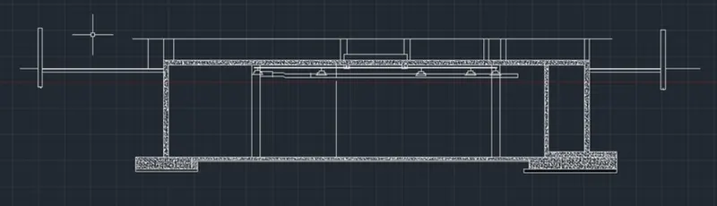
1. After sketching the basic Sectional view of the industrial building, now we have to apply to hatch
2. Select the Hatch tool by typing H or Hatch in the command box
3. Select the Hatch pattern as AR-Concrete
4. Pick the point inside the sectional view at the desired location
5. Give Hatch Scale as per requirement based on the visibility of the hatching
Step 5:
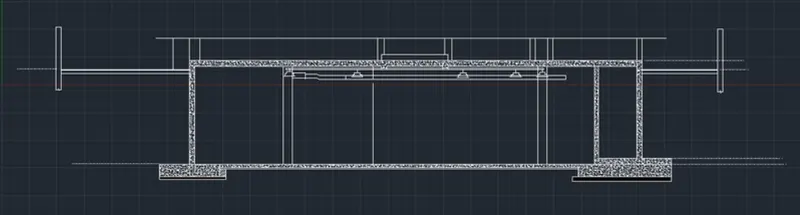
1. Select the Line tool and sketch the remaining lines as per the requirement
2. Select the Hatch tool by typing H or Hatch in the command box
3. Select the Hatch pattern as AR-Concrete
4. Pick the point inside the sectional view at the desired location
5. Give Hatch Scale as per requirement based on the visibility of the hatching
Step 6:
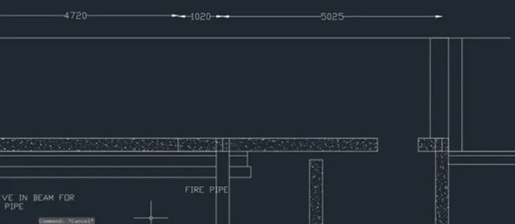
1. Enter DS in the command box to open the dimension style manager dialog
2. Modify the dimensions as per the requirement
3. Change the color of the dimension and extension line as per the requirement
4. Under the text option, Change the text height to 50mm
5. click ok, then click set current and close the dimension style manager dialog box
6. Give dimensions as per the drawing and requirement using the Dim-Linear Command
Step 7:
1. Select the Multiline Text by typing MText in the command box
2. Give the text height as 50mm as per the requirement
3. Select the text area at the desired location as per the requirement
4. Give Text as per the drawing and requirement using the MText command
RESULT:
The Section view of the Industrial Building has been sketched and provided with appropriate hatch, and dimensions as per the requirement.