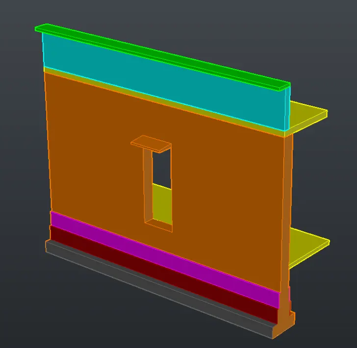
Creating 3D Isometric view of various structural elements in AutoCAD
Creating a 3D Isometric view of various structural elements in AutoCAD
1. Create a 3D Isometric View of the building with the plan and elevation given.
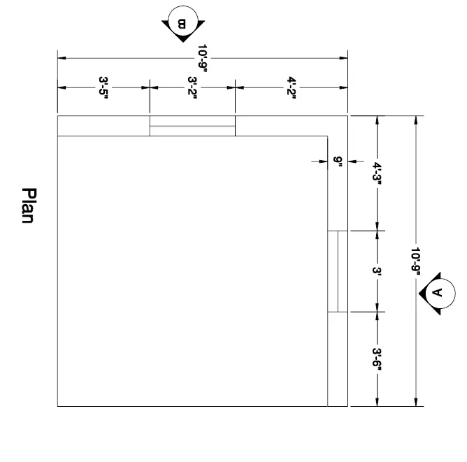
AIM:
To create a 3D Isometric view of the building with the given plan and elevation
INTRODUCTION:
Isometric drawing is a form of 3D drawing, which is set out using 30-degree angles. It is a type of axonometric drawing so the same scale is used for every axis, resulting in a non-distorted image. Since isometric grids are pretty easy to set up, once you understand the basics of isometric drawing, creating a freehand isometric sketch is relatively simple.
An isometric drawing is a 3D representation of an object, room, building, or design on a 2D surface. One of the defining characteristics of an isometric drawing, compared to other types of 3D representation, is that the final image is not distorted. This is because the foreshortening of the axes is equal. The word isometric comes from Greek to mean 'equal measure'.
COMMANDS USED:
1. Units
2. Limits
3. Rectangle
4. Line
5. Offset
6. Trim
7. Boundary
8. Region
9. Extrude
10. Copy
PROCEDURE:
Step 1:
1. Open the Autocad software from the desktop
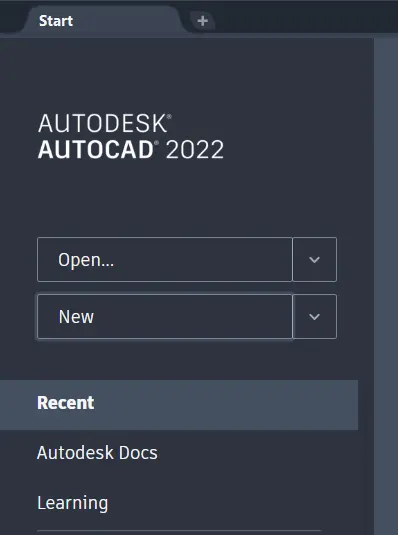
2. On the home page of the Autocad, Click on New drawing
3. Switch the model space into 3D modeling from the status bar
Step 2:
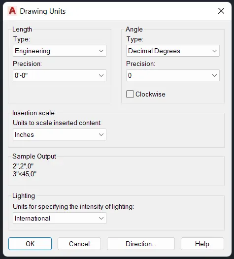
1. Type UN and set the units as Engineering and precision as 0' 0"
2. Set the units as Inches in the insertion scale
3. Type Limits in the command box and set the Lower limit as 0,0 and Upper limit as 50',50'
4. Type Z enter for Zoom Enter and A Enter for Zoom all
Step 3:
1. Go to the Top view using the UCS icon at the top right corner
2. Select the Rectangle tool by typing REC or Rectangle in the command box
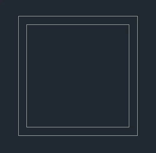
3. Draw a rectangle with a dimension of 10'9" as length and 10'9" as width
4. Select the Offset tool and give the offset distance as 9"
5. Create the offset of the rectangle through the inside as shown in the figure below
Step 4:
1. Select the Trim tool by typing TR or Trim in the command box
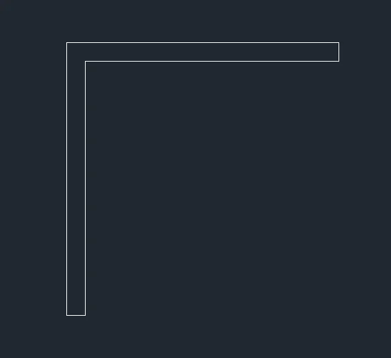
2. Trim the right sidelines, so it should look like L shaped wall
3. Using the Line command, Join the lines at the corners
4. Again using the Trim command, trim the unnecessary lines as shown in the figure below
Step 5:
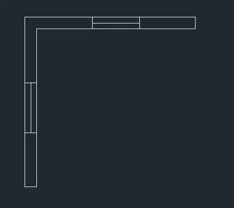
1. Select the Offset tool and give offset distance as 1'6"
2. Draw the line at the middle of the wall and offset it through the both sides
3. Using the Line command, draw the line in the middle to show the window location
Step 6:
1. Go to the Default 3D view using the UCS icon at the top right corner
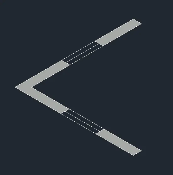
2. Select the Boundary tool by typing BO or Boundary in the command box
3. Pick the boundary point as inside of the wall and press okay
4. Select the Region tool by typing REG in the command box
5. Select the walls except for the window and press ok to make it region
Step 7:
1. Select the Extrude tool by typing EXT or Extrude in the command box
2. Extrude the region with a height of 10' into the Z-Axis
3. The Walls have been Extruded into the Z-Axis as shown in the figure below
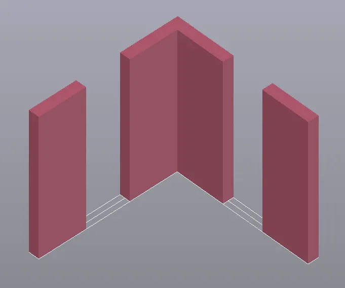
Step 8:
1. Select the Rectangle tool by typing REC or Rectangle in the command box
2. Draw a rectangle over the window portion
3. Select the Extrude tool and Extrude it to the top with a height of 3' to the sill level
4. Similarly create another rectangle at the top
5. Extrude it into the below level with a height of 3' from the top
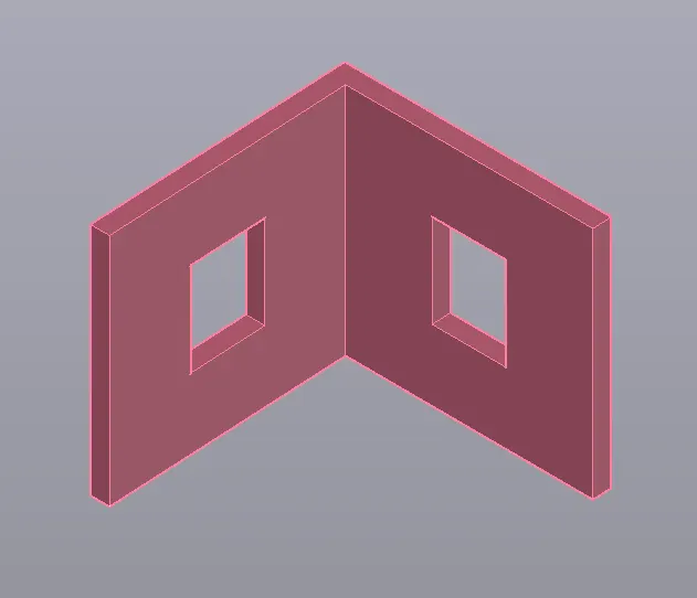
Step 9:
1. Select the Rectangle tool by typing REC or Rectangle in the command box
2. Create the window with the dimensions of 3'×3'
3. Select the Boundary tool by typing BO or Boundary in the command box
4. Pick the region and create the boundaries for the frame, mullion, and glass as shown in the figure below
5. Select the Extrude tool and Extrude it into 3" for frame and 1.2" for mullion and 0.6" for glass
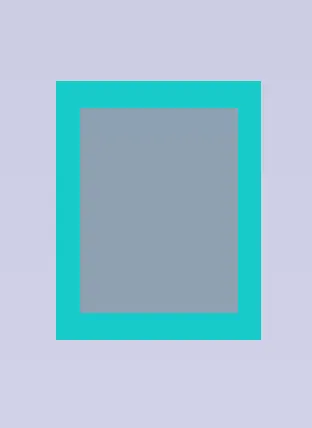
Step 10:
1. Select the Copy tool by typing CO or Copy in the command box
2. Select the whole window and copy it into the walls at the desired location
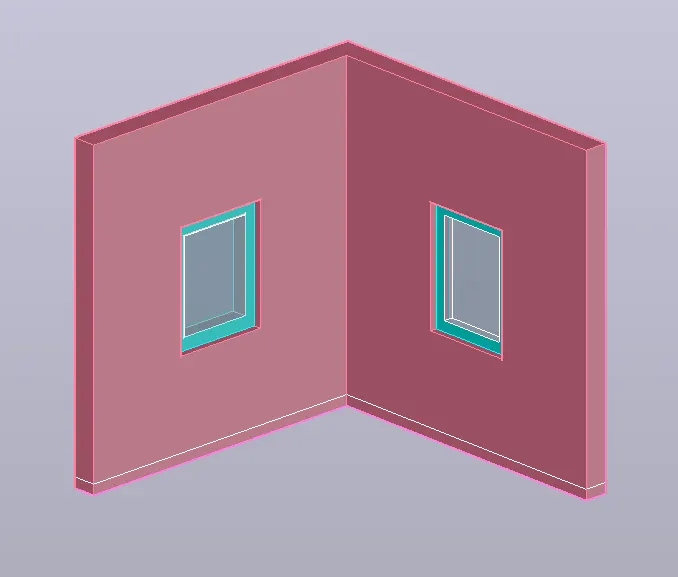
RESULT:
The 3D Isometric view of the building wall has been sketched successfully as per the given drawing
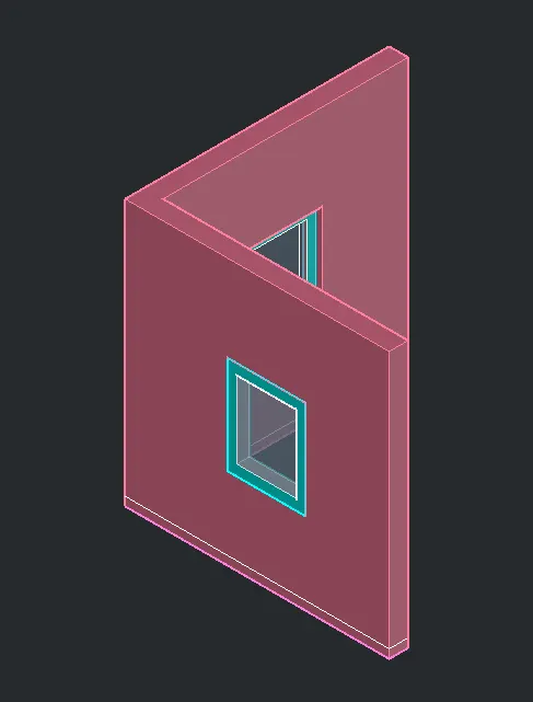
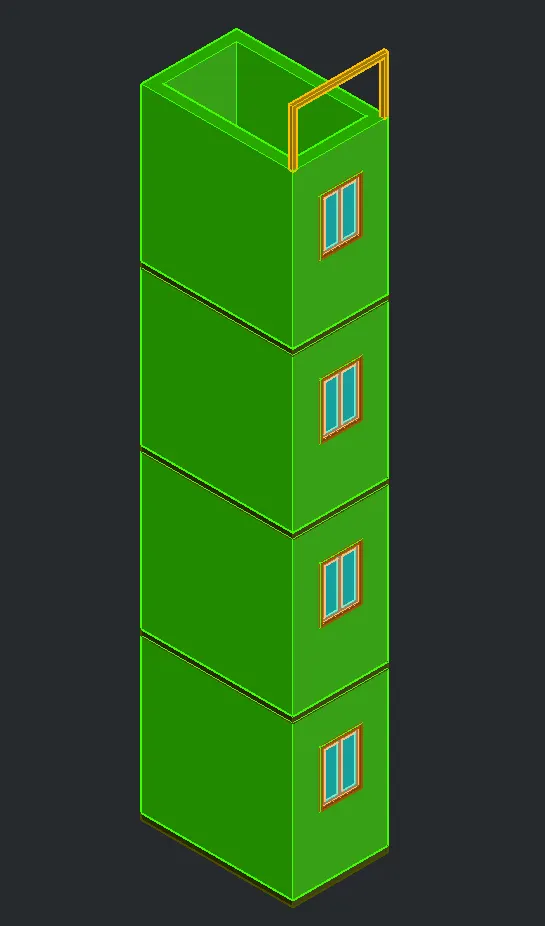
2. Create the 3D View of the Building Façade as given in the plan and elevation. Also, see the detail of the window.
AIM:
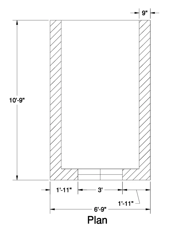
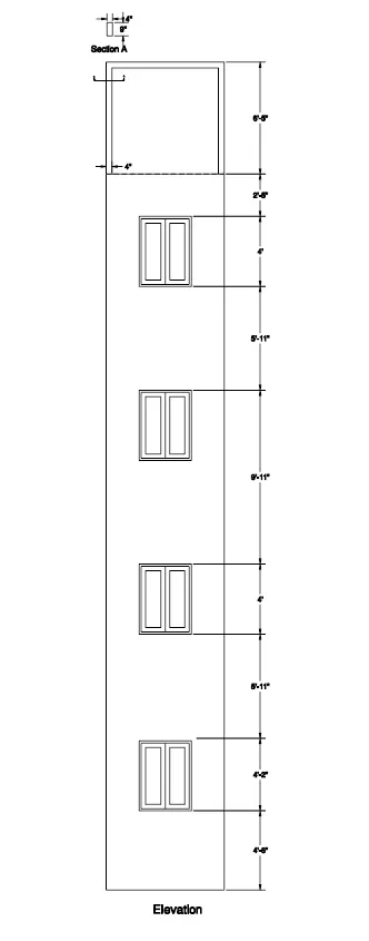
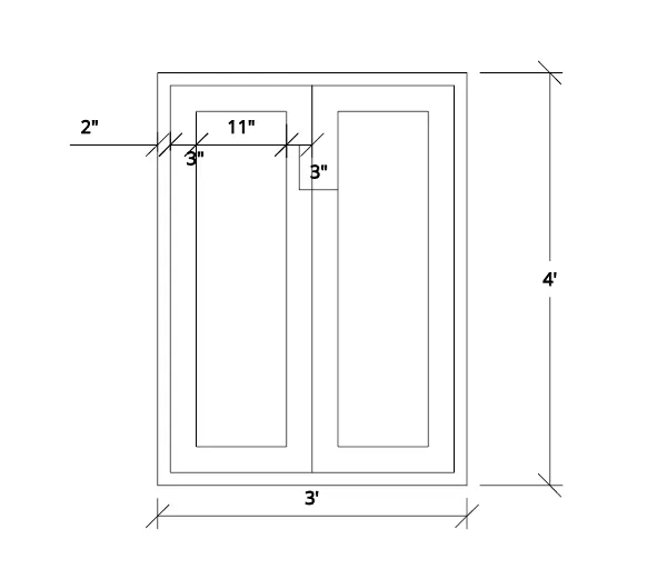
To create the 3D view of the building Facade with detail of the window as per the given plan and section
INTRODUCTION:
A building façade refers to one side, normally the front side of a building structure. It is one of the most integral pieces to the overall design of the structure, as it adds a unique personality and character to it. A building façade can be of several shapes and sizes it is one of those pieces of the structure that provides the architect with the chance to experiment and showcase their talent and bring their creations to life.
Every now Now people associate façades with older buildings or the prestigious ones, but today every building can create a recognizable façade. In addition to that, people even link a façade with something that only adds to the aesthetic factor of a building structure.
COMMANDS USED:
1. Units
2. Limits
3. Rectangle
4. Line
5. Offset
6. Boundary
7. Region
8. Extrude
9. Move
10. Copy
PROCEDURE:
Step 1:
1. Open the Autocad software from the desktop
2. On the home page of the Autocad, Click on New drawing
3. Switch the model space into 3D modeling from the status bar
Step 2:
1. Type UN and set the units as Engineering and precision as 0' 0"
2. Set the units as Inches in the insertion scale
3. Type Limits in the command box and set the Lower limit as 0,0 and Upper limit as 50',50'
4. Type Z enter for Zoom Enter and A Enter for Zoom all
Step 3:
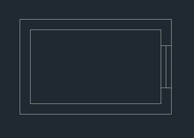
1. Select the Rectangle tool by typing REC or Rectangle in the command box
2. Create a rectangle of dimensions 10'9" and 6'9"
3. Select the Offset tool and give the offset distance as 9"
4. Offset the previous rectangle into the inside as shown in the figure below
5. Select the Line tool and create the window on the right side of the wall as shown in the figure below
Step 4:
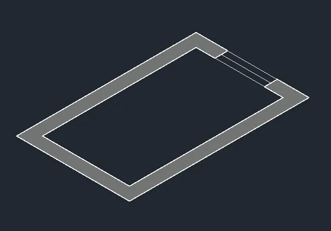
1. Select the Boundary tool by typing BO or Boundary in the command box
2. Pick the point inside and create the boundary section of the rectangle
3. Select the Region tool by typing REG in the command box
4. Select the Rectangle and press ok to create the region
Step 5:
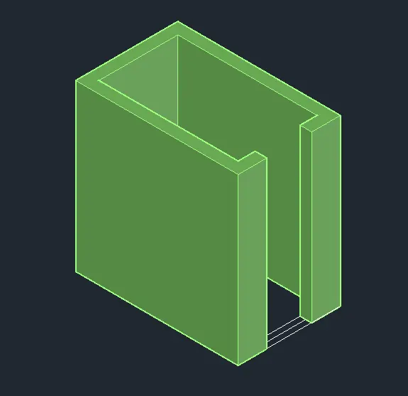
1. Select the Extrude tool by typing EXT or Extrude in the command box
2. Extrude the rectangle with a height of 10'11" at the top
3. Total height of the wall is 10'11" ( Sill height = 4'6", Window height= 4', Top height from the window = 2'5")
Step 6:
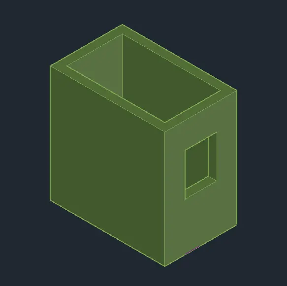
1. Select the Rectangle tool and draw a rectangle below at the window portion
2. Select the Extrude tool and Extrude into the top with a height of 4'6"
3. Similarly create another rectangle at the top of the window portion
4. Select Extrude tool and Extrude below with a height of 2'5"
Step 7:
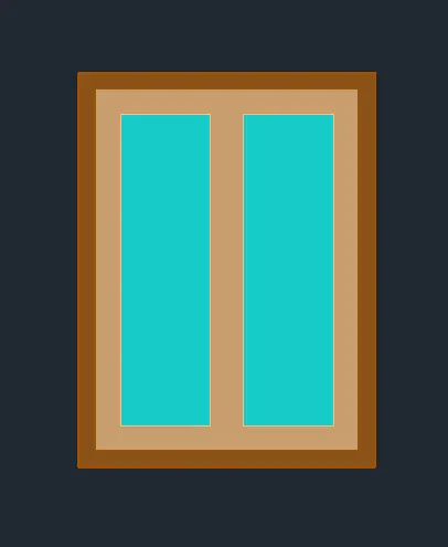
1. Select the Rectangle tool and draw a rectangle of dimension 4'×3' in the Top view
2. Select the Offset tool and give offset distance as 2" for the frame, 3" for mullion, and 1.2" for glass
3. Offset the rectangle to the inside as shown in the figure below
4. Select the Boundary tool and create a region in the frame, mullion, and glass section respectively
5. Select the Extrude tool and Extrude 3" for the frame, 1.6" for mullion, and 1" for glass
6. Using Layer Tool, provide appropriate layers as shown in the figure below
Step 8:
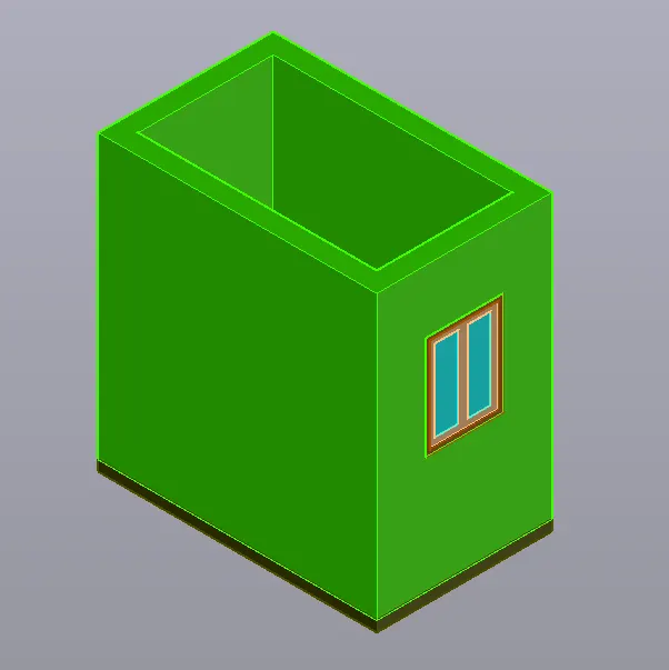
1. Select the Move tool by typing M or Move in the command box
2. Select the window and move it into the wall to the desired location
3. Select the Rectangle tool and create the rectangle itself for the roof.
4. Select the Extrude tool and Extrude the rectangle by 5" at the below
Step 9:
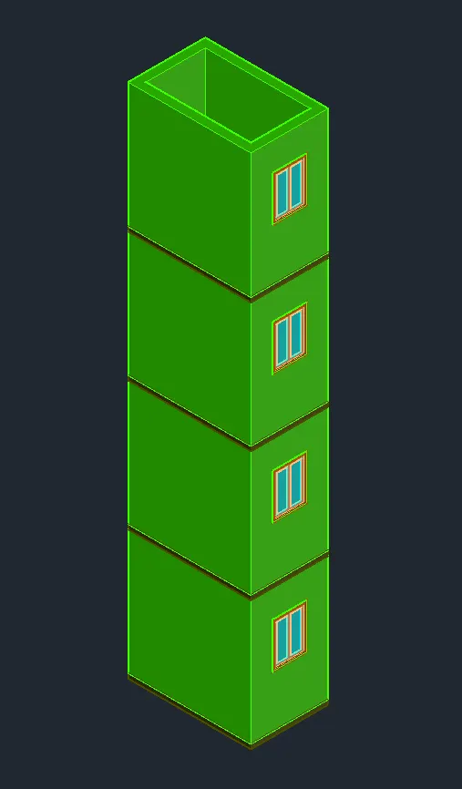
1. Select the Copy tool by typing CO or Copy in the command box
2. Copy the First floor and move it into the desired location for the four floors.
Step 10:
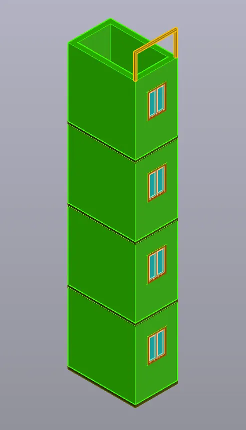
1. Select the UCS tool by UCS in the command box
2. Place the UCS on the top surface of the building
3. Draw a rectangle with a dimension of 9"×4" at the top level
4. Select the Extrude tool and Extrude the rectangle by 4"
RESULT:
The 3D view of the building Facade with the detail of the window has been created successfully as per the given drawing
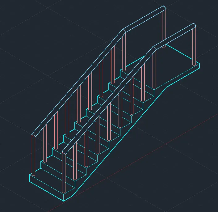
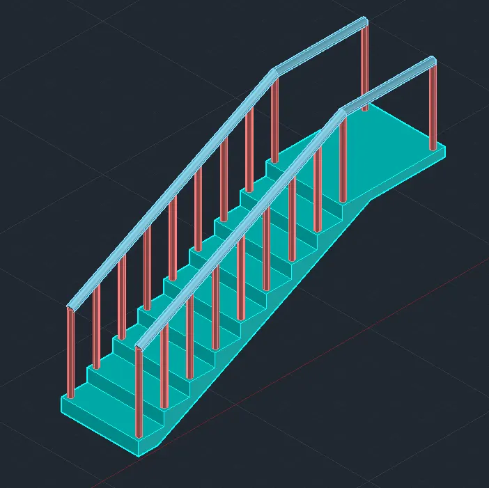
3. Create the isometric 3d view of a stair with a railing as shown in the plan and elevation. Assume the size of the balustrades and the handrails.
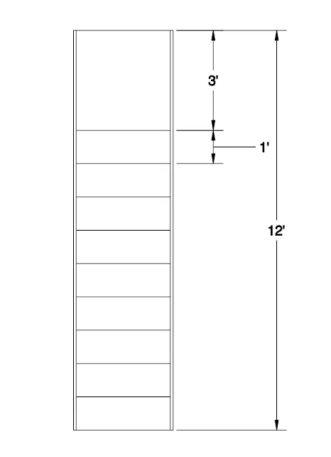
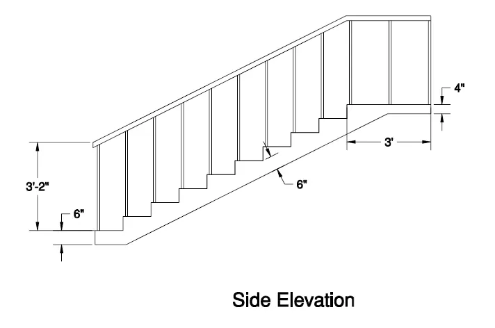
AIM:
To create the 3D Isometric view of a stair with a railing as per the given plan and section
INTRODUCTION:
A stair is a set of steps leading from one floor of a building to another, typically inside the building. The room or enclosure of the building, in which the stair is located is known as a staircase. The opening or space occupied by the stair is known as a stairway.
Types of stairs used in building construction are broadly based on the shape of the stairs. Straight stairs, Turning stairs, and Continuous stairs are broad types of stairs.
COMMANDS USED:
1. Units
2. Limits
3. Line
4. Copy
5. Boundary
6. UCS
7. Extrude
8. Circle
9. 3DPoly
10. Mirror
11. Sweep
PROCEDURE:
Step 1:
1. Open the Autocad software from the desktop
2. On the home page of the Autocad, Click on New drawing
3. Switch the model space into 3D modeling from the status bar
Step 2:
1. Type UN and set the units as Engineering and precision as 0' 0"
2. Set the units as Inches in the insertion scale
3. Type Limits in the command box and set the Lower limit as 0,0 and Upper limit as 50',50'
4. Type Z enter for Zoom Enter and A Enter for Zoom all
Step 3:
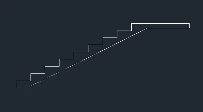
1. Go to the Front view by using the UCS icon at the top right corner
2. Select the Line tool by typing L or Line in the command box
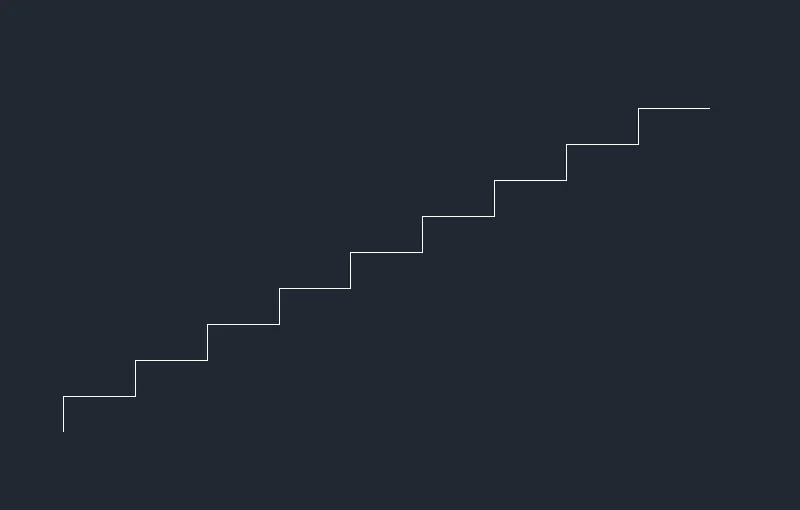
3. Using the Line tool, draw the rise as 6" and tread as 1'
4. Select the Copy tool and Copy the tread and rise into different levels as shown in the figure below
Step 4:
1. Select the Line tool again and draw a line of length 3' for the waist slab
2. Draw another line below with the thickness of 4" for the waist slab
3. Connect the waist slab and below tread to form a section of the stair
Step 5:
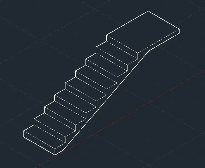
1. Go to the Default 3D view by using the UCS icon
2. Select the Boundary tool and create a region inside the section
3. Select the Extrude tool and Extrude the section to the left side with an extrude height of 3"
Step 6:
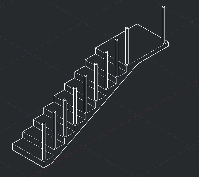
1. Select the UCS tool by typing UCS in the command box
2. Place the UCS icon on the tread to create the handrails
3. Select the Circle tool and create the circle with a radius of 2" on the tread
4. Select the Extrude tool and Extrude the circle with a height of 3'
5. Select the Copy tool Copy the Circle and move it to the other treads as shown in the figure below
Step 7:
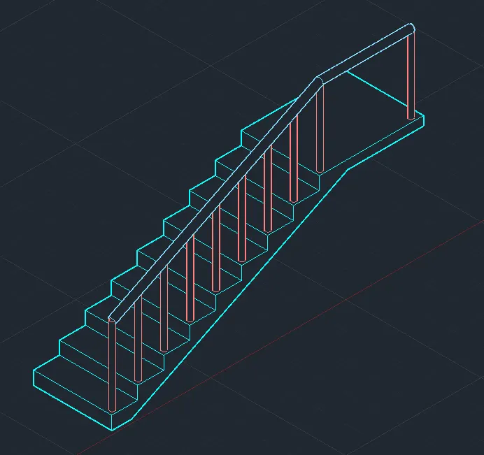
1. Select the 3D Polyline by typing 3P in the command box
2. Draw the Polyline starting at the point of the first circular column to the last column
3. Draw another circle with a radius of 2"
4. Select the Sweep tool and select the Circle to sweep it into the Polyline
Step 8:
1. Select the Mirror tool by typing MI or Mirror in the command box
2. Select the balustrades and handrails and mirror them through the other side as shown in the figure below
RESULT:
The 3D Isometric view of the Stair with railing has been sketched successfully as per the drawing
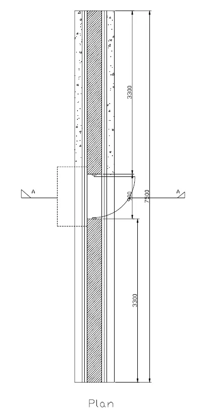
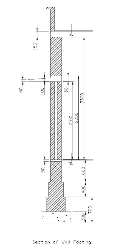
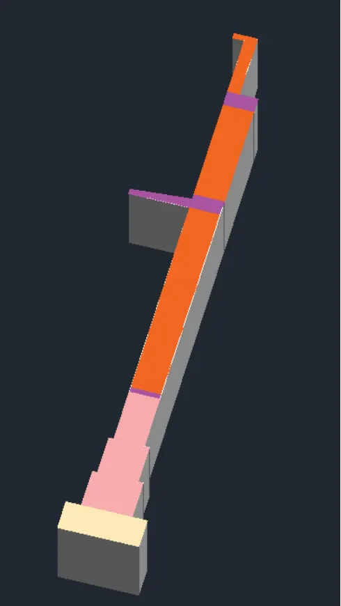
4. Create the 3D view of a Wall with spread footing. Create the Door opening only. Assume the size of the parapet and the coping. See the plans and elevation for the details. Also, create a rendered view of the model with materials of your choice.
AIM:
To create the 3D view of the wall with spread footing as per the given plan and elevation details
INTRODUCTION:
The spread footing is utilized to support the column & walls and additionally to convey & disseminate the load coming to the structure to the soil below it.
This type of footing may be a circular, square, or rectangular slab of uniform thickness and to spread the load over a sizeable area sometimes it’s stepped. The base of the spread footing is slightly wider than the load-bearing foundation base. This is also called a stepped spread foundation.
The spread footings are constructed with concrete & steel and, because of their design, they’re less likely to fail than other spot footers.
COMMANDS USED:
1. Units
2. Limits
3. Line
4. Offset
5. Extend
6. Boundary
7. Circle
8. Hatch
PROCEDURE:
Step 1:
1. Open the Autocad software from the desktop
2. On the home page of the Autocad, Click on New drawing
3. Switch the model space into 3D modeling from the status bar
Step 2:
1. Type UN and set the units as Decimal and precision as 0.0
2. Set the units as Millimetres in the insertion scale
3. Type Limits in the command box and set the Lower limit as 0,0 and Upper limit as 10000,10000
4. Type Z enter for Zoom Enter and A Enter for Zoom all
Step 3:
1. Go to Top view using the UCS icon at the top right corner
2. Select the Line tool by typing L or Line in the command box
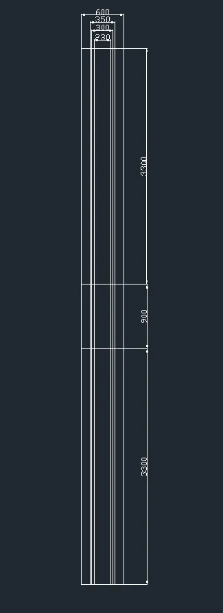
3. Draw a vertical line of length 7500mm and 230mm in width
4. Draw a center line in the wall and offset 150mm on both sides
5. Select the Offset tool again and give the offset distance as 25mm
6. Select the 300mm line and offset it through outside
7. From the center line again give an offset of 300mm and offset it through both sides
8. By using Extend command, extend the horizontal lines
9. Select the Offset tool again and give the offset distance as 3300mm
10. Select the horizontal line and offset both sides for the door opening of 900mm
Step 4:
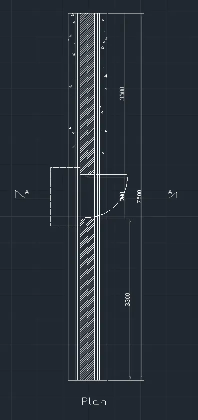
1. By using the Circle tool and Line tool, create the door opening
2. Select the Hatch tool by typing H or Hatch in the command box
3. Select Hatch pattern as ANS 132 for wall, Solid for footing, and AR- CONC for bottom P.C.C
Step 5:
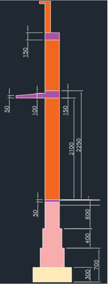
1. Create the Lintel by using the Line command and do the hatching
2. At the top of the section, Use break lines to represent the section
3. Select the DimLinear command, and provide the necessary dimensions
Step 6:
1. Go to the Default 3D view using the UCS icon at the top right corner
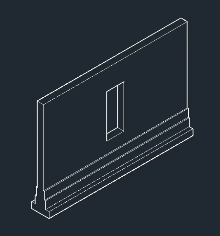
2. Create a profile for the footing step in the 2D plan and copy it through the 3D plan with the help of the Snap tool
3. Select the Boundary tool and pick inside the footing to create the region
4. Select the Extrude tool, Extrude the region by 400mm
5. Similarly do the same procedure for the remaining profiles as shown in the figure below
6. Select the rectangular profile of the lintel beam and move it by using the Move command at the distance of @0,0, -1050
7. Select the Extrude tool and Extrude it at a height of -150mm
8. To create the top portion of the wall, create the rectangle at the top face
9. Select Extrude tool and extrude it to a height of -1050mm
10. Select the Union tool, and make the extruded part as the union of the wall
Step 7:
1. By using the Union command, group it into a single entity
2. By using Layer Tool, provide appropriate layers to the section of the wall
RESULT:
The 3D view of the wall with Spread footing has been sketched successfully as per the given drawing