Modelling of 25 storey building with the specified properties using ETABS
Challenge 6 – ETABS modeling of a 25-story building
Question:
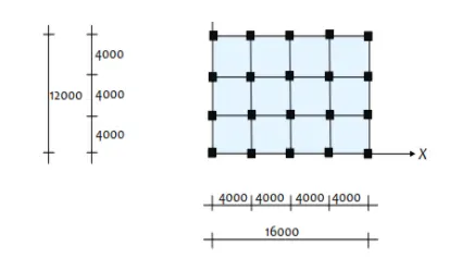
Model a 25-story building on ETABS with structural properties as specified below. The ground floor or plinth floor level can be taken at a height of 1.5 meters from the base. Each of the successive 25 stories has a story height of 3 meters
Structural Element Sizes:
- Beams : 300 × 400 mm
- Columns : 800 × 800 mm
- Slab: 150 mm thick
Material Properties:
- Grade of Concrete: M30
- Grade of Steel Reinforcement Bars: Fe 415
Loading:
- Dead Load on beams from infill wall: 10 kN/m (Let us assume the same for the roof floor given parapet)
- Live load on the floor : 3 kN/m2 (Let us assume the same for the roof floor)
a) Buildings are assumed to be pinned at the base
b) All columns in all stories are of the same size
c) All beams in all stories are of the same size
d) Building is located on Soil type II and in Zone III. Assume other factors if required.
Carry out the following exercises:
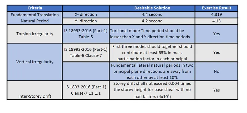
- Check if the translational fundamental natural period of vibration in both the x and y direction is approximate: where Tx1= 4.4 seconds and Ty1= 4.2 second
This check will help confirm if the modeling is done correctly. Some deviations from the above values are possible (± 2%). But any major deviation will suggest an error in modeling.
- Check if the following provision in Table 5 of IS 1893 (part 1) – 2016, on torsional irregularity is satisfied:
The natural period corresponding to the torsional mode of oscillation must be less than the two fundamental translational modes of oscillation along each principal plan direction.
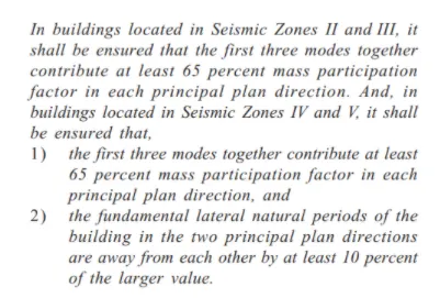
- Check if the two provisions of clause 7 in Table 6 (shown below) of IS 1893 (part 1) – 2016, regarding vertical irregularity is satisfied
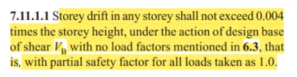
- Check if the provision on inter-story drift limitations in clause 7.11.1.1 is satisfied. Please note that this check is for Serviceability Limit State and hence is for the situation when the structure is subjected to unfactored seismic base shear
Answer:
AIM:
To Model, a 25-story building on ETABS with structural properties as specified and ground floor or plinth floor level can be taken at a height of 1.5 meters from the base. Each of the successive 25 stories has a story height of 3 meters
INTRODUCTION:
ETABS is the abbreviation of " Extended3D Analysis of Building System". ETABS is a product of Computers and Structures, Inc., recognized globally as the pioneering leader in structural engineering analysis and design software for structural and earthquake engineering.
ETABS is an engineering software product that caters to multi-story building analysis and design. Modeling tools and templates, code-based load prescriptions, analysis methods, and solution techniques, all coordinate with the grid-like geometry unique to this class of structure. Basic or advanced systems under static or dynamic conditions may be evaluated using ETABS.
PROCEDURE:
Step 1:
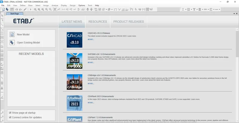
1. Open the ETABS software on your desktop
2. Click on the file menu and choose to create a New Model option
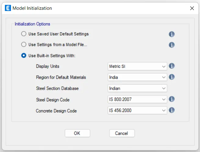
3. After Choosing the new model, a dialogue box will appear as model initialization
4. Choose the built-in settings option as the default
5. Select the display units as Metric SI, Region for default materials as India, steel section database as Indian, steel design code as IS 800:2007, and Concrete design code as IS 456:2000
Step 2:
1. After Choosing the default settings, a dialog box will appear as New model quick templates
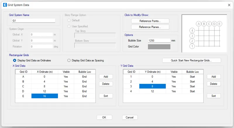
2. Select the Custom grid Spacing option and edit the X grid data as A-0, B-4, C-8, D-12, E-16
3. Similarly edit the Y grid data as 1-0, 2-4, 3-8, and 4-12 as shown in the figure below
4. Now click on Ok and Select the custom story data option
5. Edit the Custom story data as per the number of stories
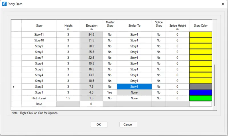
6. Edit the first story as plinth level and give height as 1.5m
7. Add another 25 stories with a height of 3m
8. Storey 1 has been labeled as the master story and all other above stories labeled as similar to that as shown in the figure below
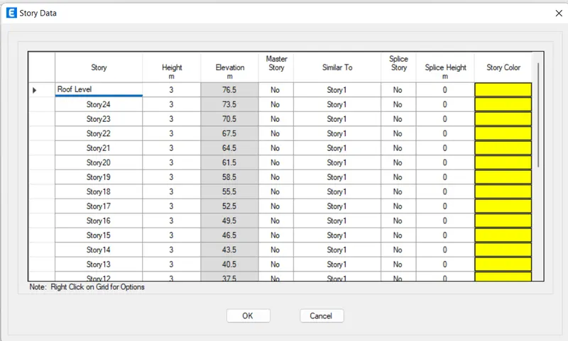
9. After adding and editing all 25 stories, click on ok
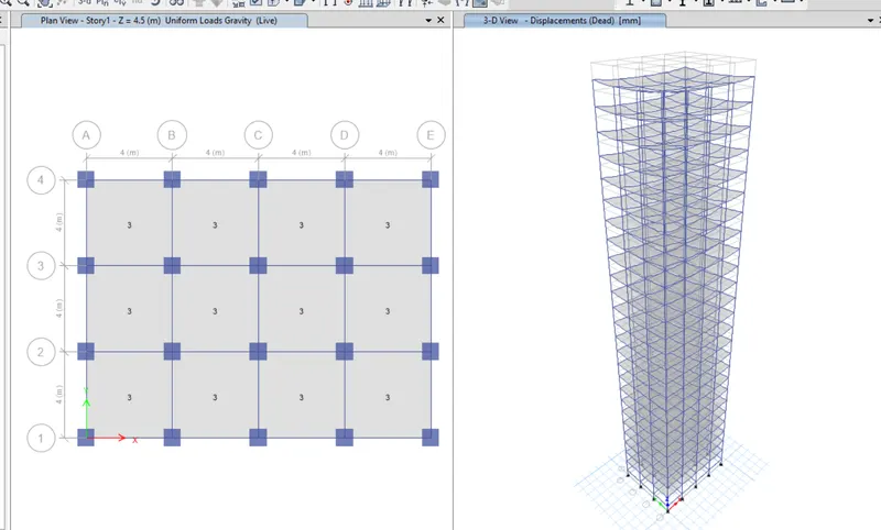
10. The 25 stories are successfully added to the project as shown in the figure below
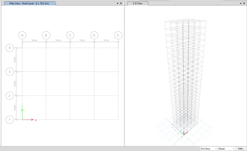
Step 3:
1. Go to the defined tab and select the material properties option
2. Click on Add new material option
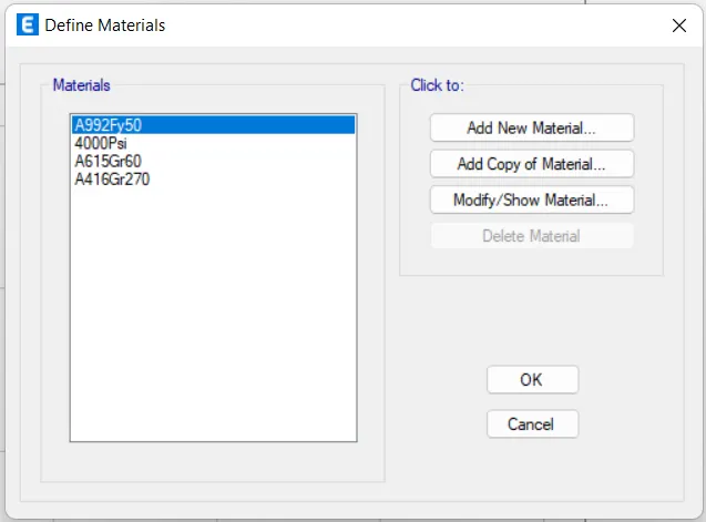
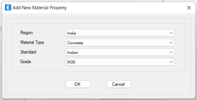
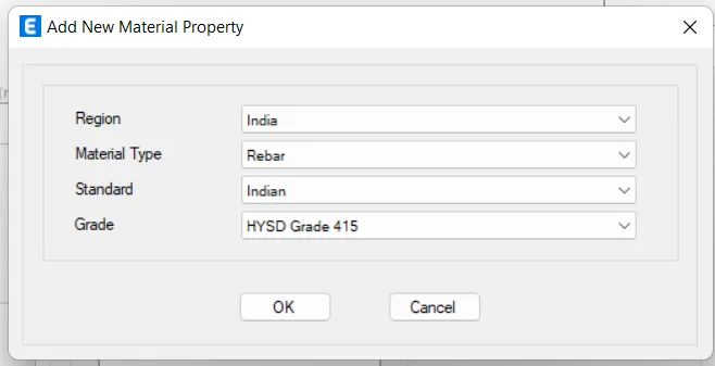
3. Add new Concrete material property by choosing Region as India, Material type as Concrete, Standard as Indian, and Grade as M30
4. After selecting all the options then click ok
5. Similarly add rebar material by choosing Region as India, Material type as Rebar, Standard as Indian, Grade as HYSD Grade 415
Step 4:
1. Now we have to define the Section properties of beams and columns
2. Go to the defined tab and select the section properties and then select frame sections
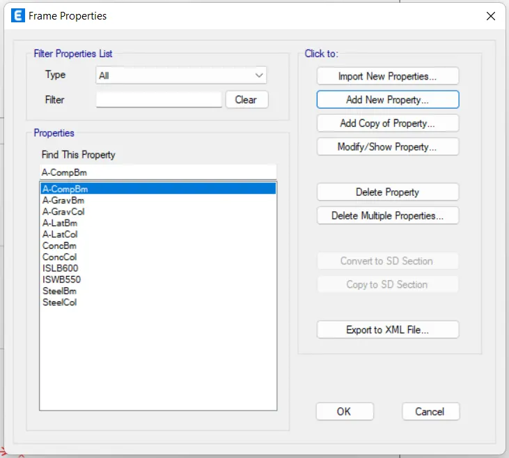
3. Click on add new material
4. Then select the section shape as Concrete Rectangular and Shape type as shown in the figure below
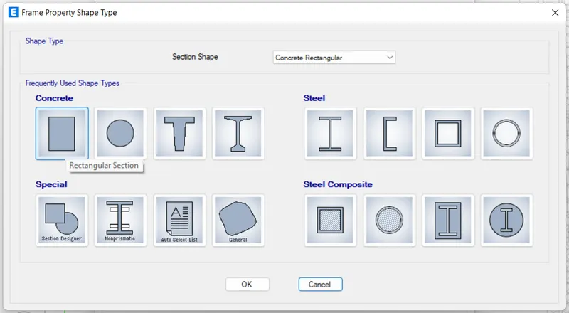
5. After clicking ok, a new dialog box will appear as frame section property data
6. Select the property name as B300x400, Material as M30
7. Give the section dimensions of width 400mm and depth 300mm
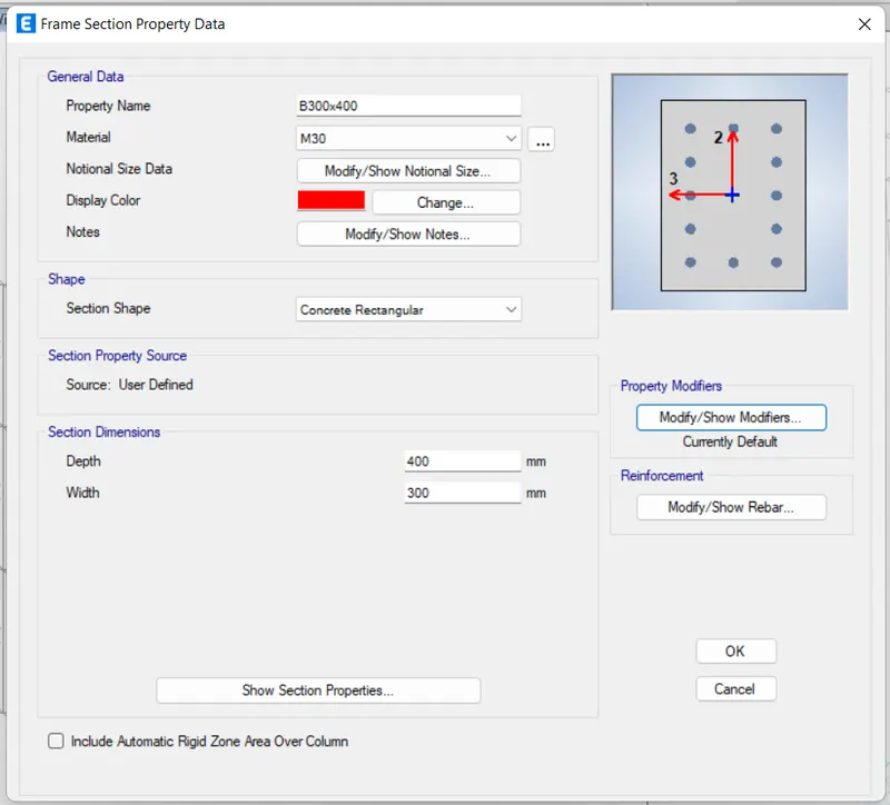
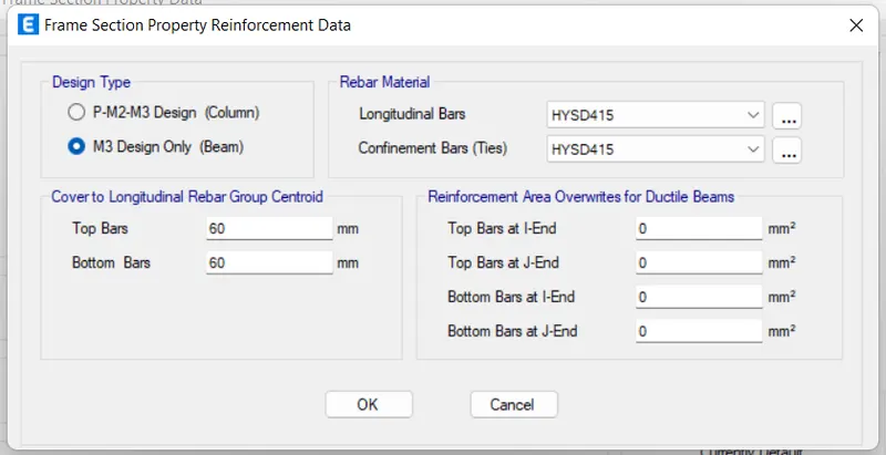
8. Then click on modify/show rebar option, and a new dialog box will appear as Frame section property reinforcement data
9. Select the design type as M3 design only (Beam) and rebar materials as HYSD 415 as shown in the figure below
10. Similarly we have to add column properties
11. Click on add new material
12. Then select the section shape as Concrete Rectangular and Shape type as shown in the figure below
13. After clicking ok, a new dialog box will appear as frame section property data
14. Select the property name as C800x800, Material as M30
15. Give the section dimensions of width 800mm and depth 800mm
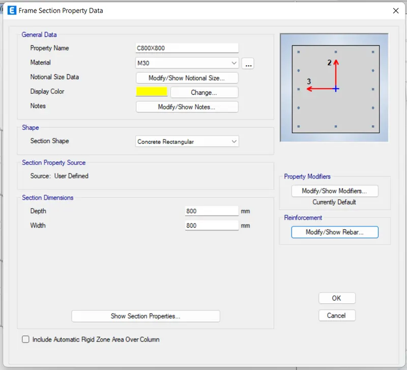
16. Then click on modify/show rebar option, and a new dialog box will appear as Frame section property reinforcement data
17. Select the design type as P-M2-M3 design (Column) and rebar materials as HYSD 415 as shown in the figure below
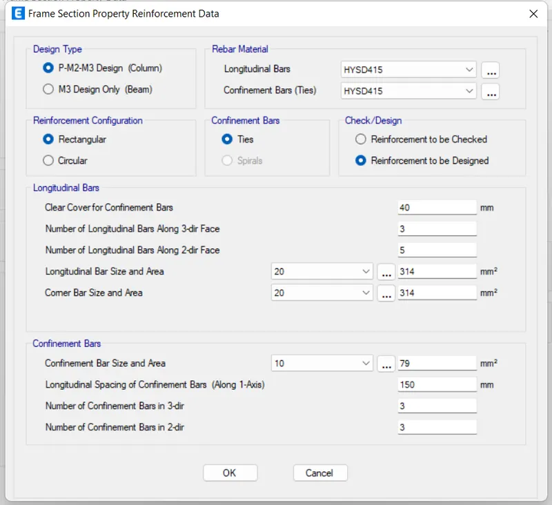
18. After providing all the data, click on press ok
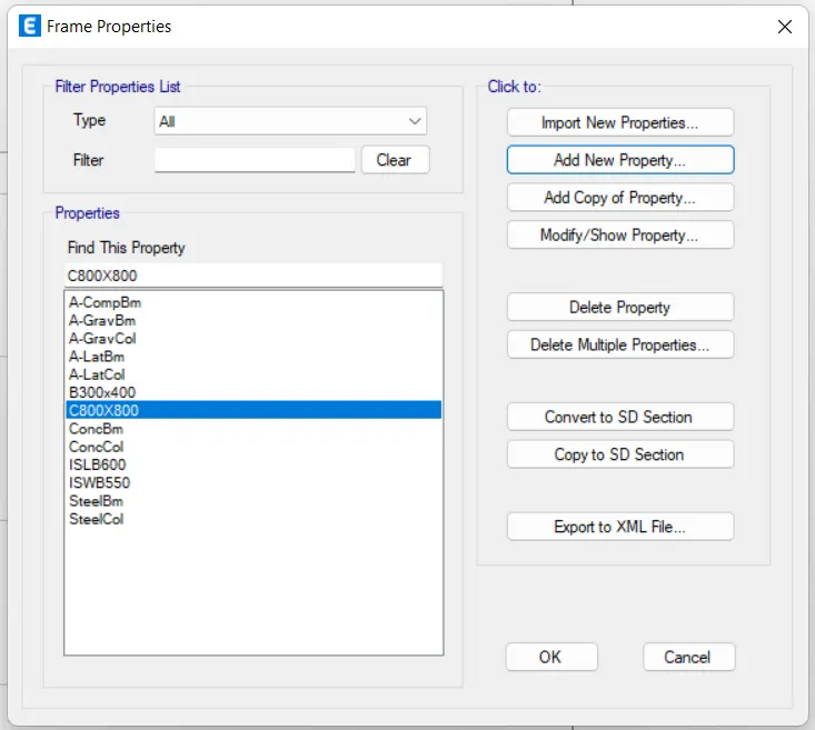
19. Then Beam and Column properties have been successfully added
Step 5:
1. Now we have to define the slab property
2. Go to the defined tab, select the section properties, and then select slab sections
3. Select Add new property
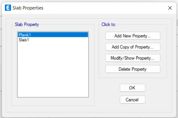
4. Give the property name as slab150 and slab material as m30
5. Select the modifying type as membrane
6. Then select the property data of type as slab and give thickness as 150mm as shown in the figure below
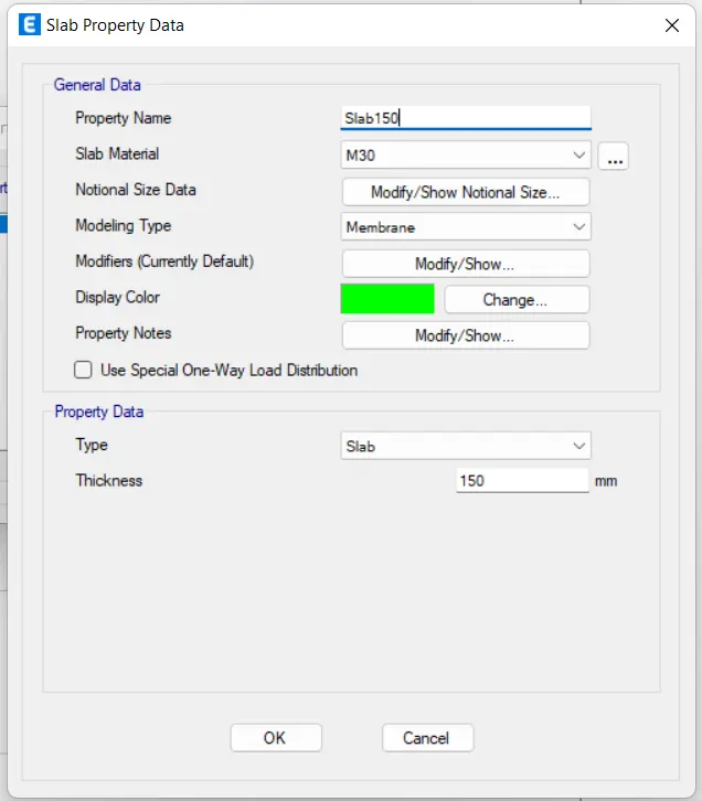
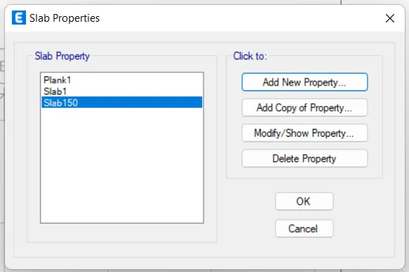
7. After giving all the data, click on press ok
8. The slab material has been successfully added
Step 6:
1. Now we have to define various load patterns and load combinations
2. Go to the defined tab and select the load patterns option
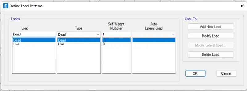
3. By default there is a dead load and live load, now we have to add other loads
4. Give the name of the load as Wall and select the type as super dead, then click on add new load
5. Similarly add EQX and EQY load by selecting the type as seismic and Auto lateral load as IS 1893:2016
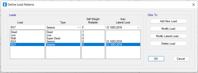
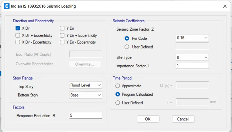
6. Select the EQX load and click on modify the lateral load
7. Then select only the 'X Dir' in direction and eccentricity
8. Then give the value of seismic zone factor as 0.16 and site type ad Zone 2.
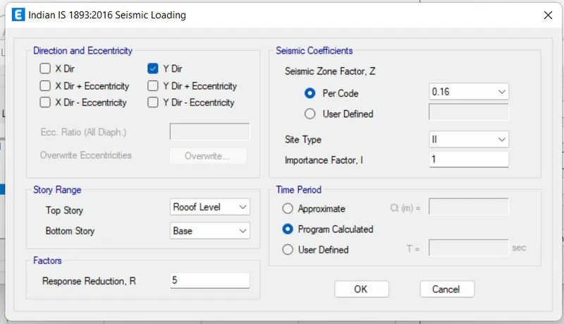
9. Similarly select the EQY load and click on modify the lateral load
10. Then select only the 'Y Dir' in direction and eccentricity
11. Then give the value of seismic zone factor as 0.16 and site type ad Zone 2
12. After adding all the required loads, click on ok
 \
\
Step 7:
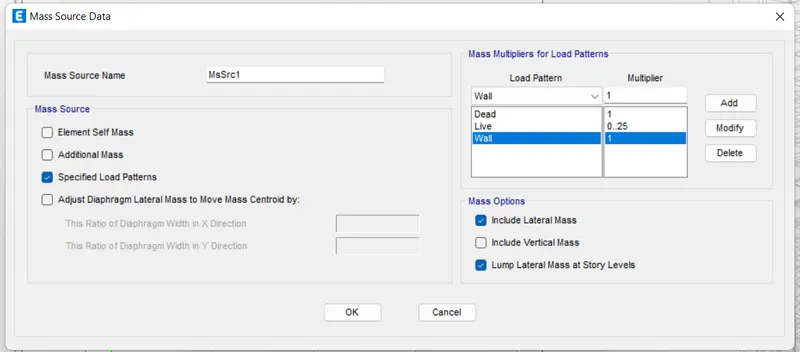
1. Go the to define tab and select the mass source option
2. Click on Add new mass source
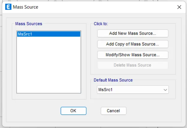
3. Select the mass source as specified load patterns
4. Add the load patterns with a multiplier by choosing Dead load as 1, Live load as 0.25, and Wall load as 1
5. After making changes click on ok
Step 8:
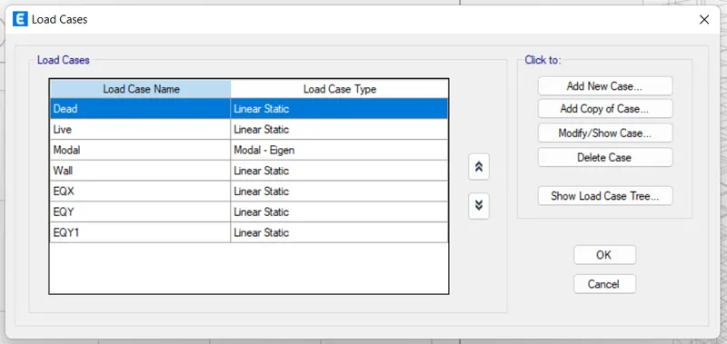
1. Gothe to define tab and select the load cases option
2. Check whether all the loads are there or not
3. Then after checking all the loads, Click on OK
4. Then again get to the defined tab and select the load combinations option
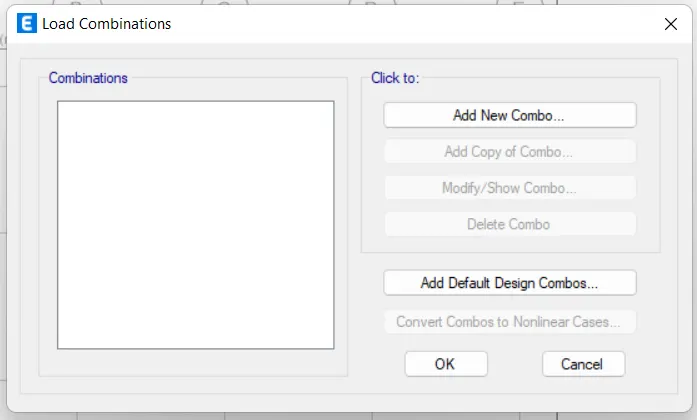
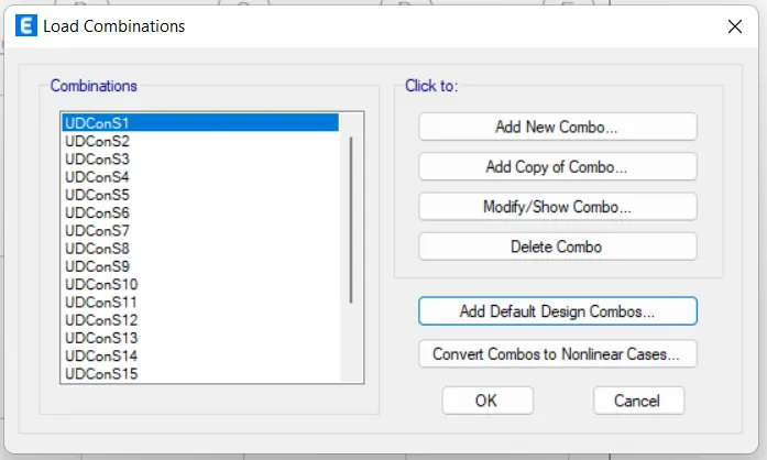
5. Select the option Add default design combos
6. Select the design type for load combinations as Concrete frame design
7. Then Turn on convert to user combinations (Editable) and press ok
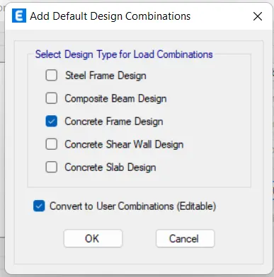
8. All the load combinative has been successfully added
Step 9:
1. Now we have to model the columns, beams, and slab selection
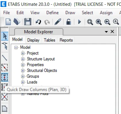
2. Select the Quickdrawdraw column on the toolbar
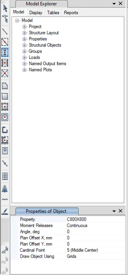
3. Select the properties of the object as C800x800 as shown in the figure below
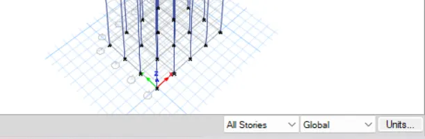
4. We have to model the columns on all stories
5. So select the all stories option in the right corner of the screen
6. Select each grid and the column will be specified on that grid automatically
7. Similarly select all the grids that we want to draw the columns
8. The column has been specified at the grids as shown in the figure below
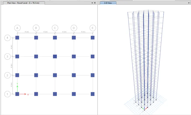
Step 10:
1. Now we have to model the beams
2. Select Quickdrawdraw beams on the toolbar
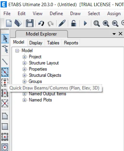
3. Select the properties of the object as B300x400
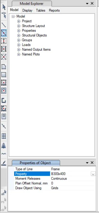
4. Select the grid line that we want to draw the beams
5. Here we specified beams the on left side grid line the and top grid line
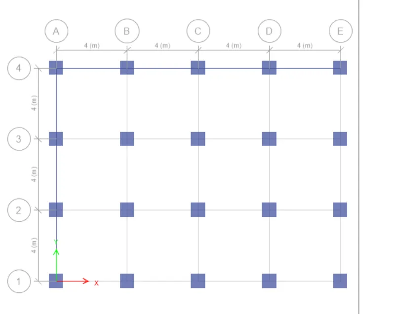
6. Now we have to replicate the same in all grid lines
7. Go to the edit tab and select the replicate option
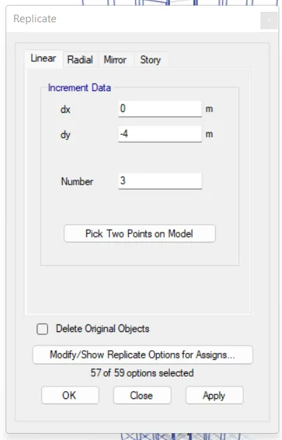
8. Select the increment Y data as -4 and number as 3, then click on ok
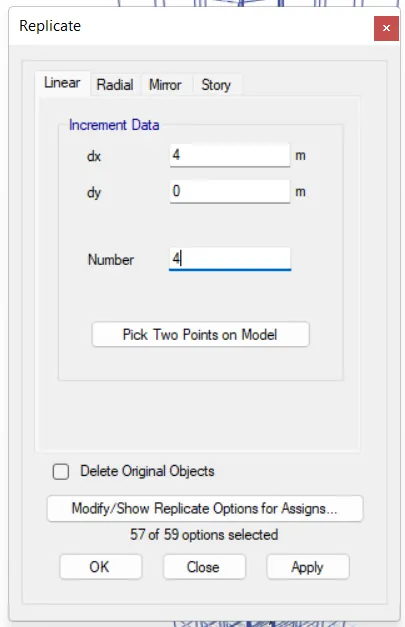
9. Similarly select replicate tool again and now this time give increment X data as 4 and number as 4
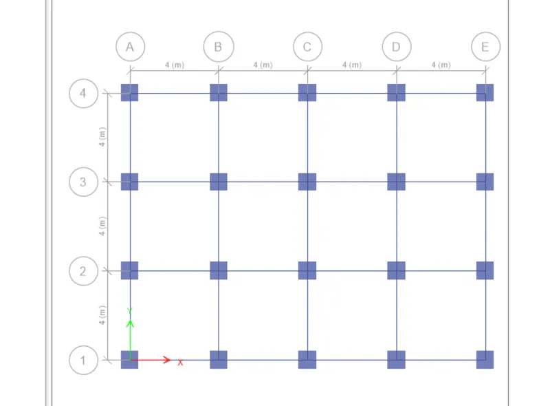
10. Then click on ok. All the behaviors have been specified on the grid lines as shown in the figure below
Step 11:
1. Now we have to model the slab sections between the grids
2. But we have to model the slabs above the plinth level
3. Go to the menu bar and select the PLAN option
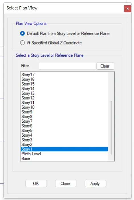
4. Select story 1 in the plan view and click on ok
5. Change the Stories into similar stories at the bottom right corner of the screen
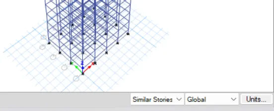
6. Now select the Quickdrawdraw Floor/wall option from the toolbar
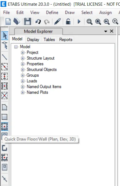
7. Select the properties of the object as Slab150
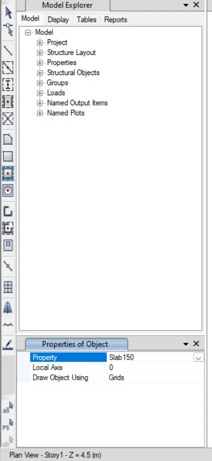
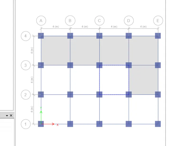
8. Select center of the each grid section to draw the slab
9. The slabs will automatically draw between each grid as shown in the figure below
Step 12:
1. to Go the select tab on the menu bar and select properties
2. Then select the frame sections option
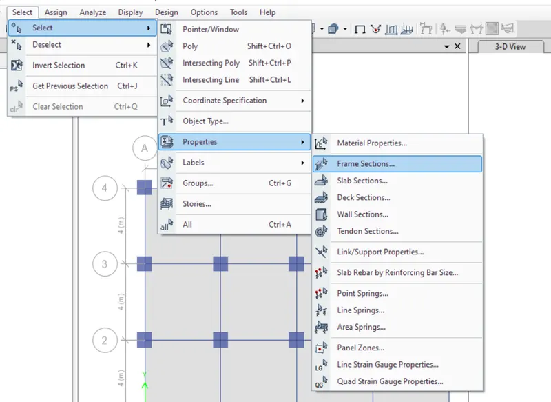
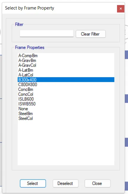
3. A dialog box will appear as selected by the frame properly
4. Select the Beam as B300x400 and click on select
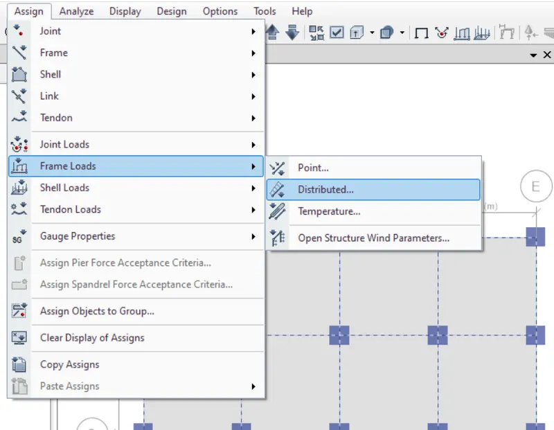
5. Then go to the assigned tab and select the frame loads and then distributed
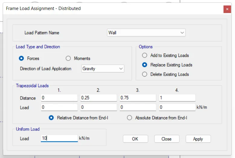
6. A new dialog box will open as Frame load assignment- Distributed
7. Select the Load pattern name as Wall and give the uniform load value as 10 Kn/m
8. Then click on OK
9. Then again go to the select the tab and select the properties and then select slab sections
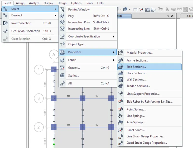
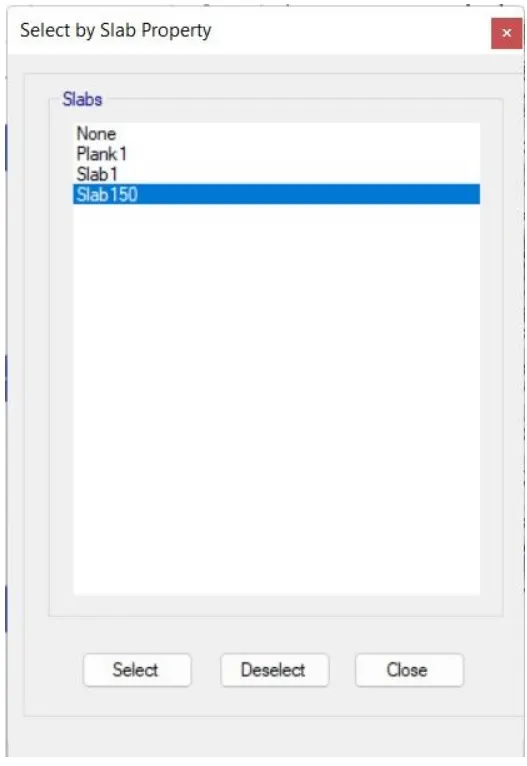
10. A new dialog box will open as Select by slab property
11. Select the slab150 and click on select option
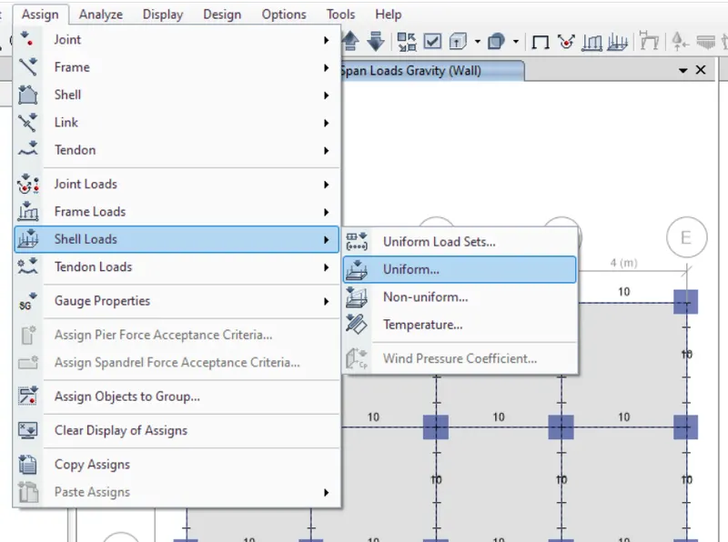
12. Then go to the assigned sign tab and select the Shell loads and then select Uniform
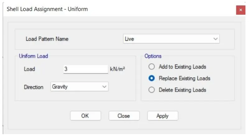
13. A new dialog box will open as Shell load assignment- Uniform
14. Select the Load pattern name as Live and give the uniform load value as 3 Kn/m^2
15. Then click on OK
16. Then again go to the assigned tab and select the Shell option and then select diaphragms
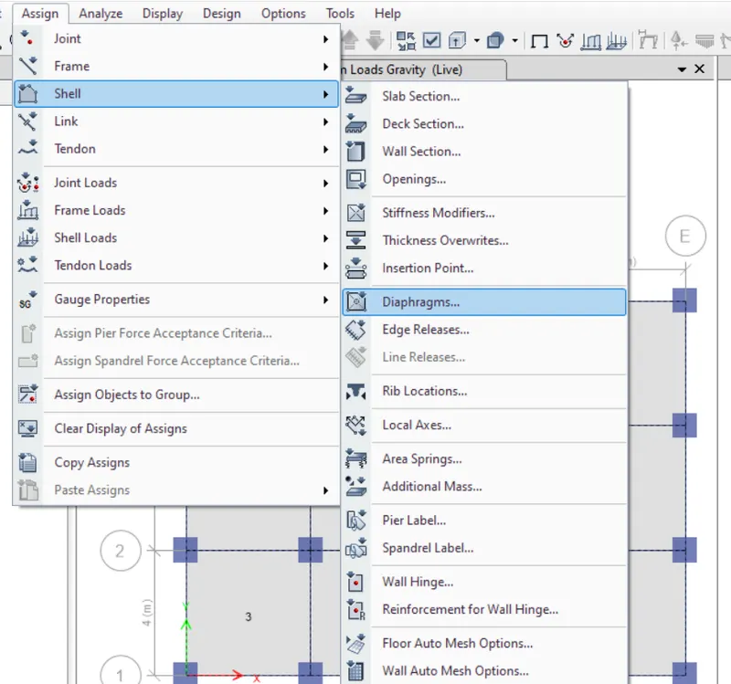
17. A new dialog box will open as Shell assignment- Diaphragms
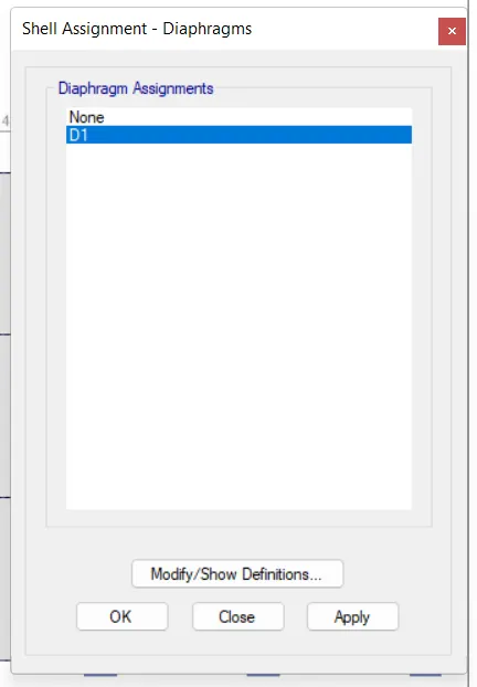
14. Select the D1 option and click on OK
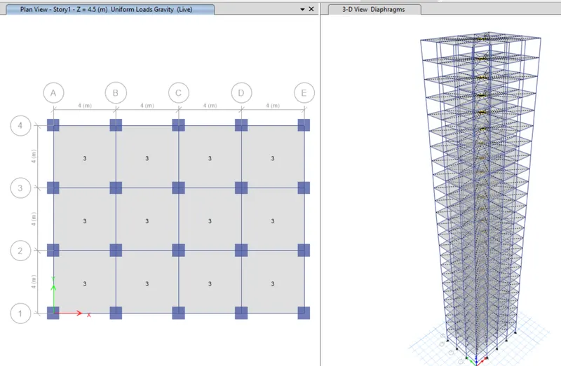
15. All loads and diaphragms have been assigned to the model
Step 13:
1. Then the Analysisysis
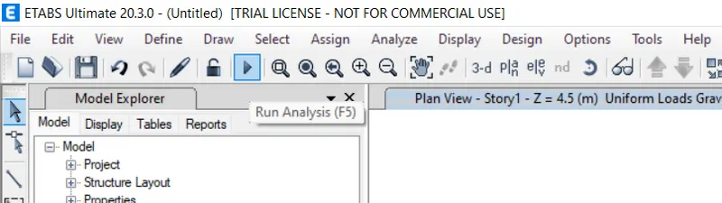
2. The model analysed the deflection patterns and cross-checked them logically.
RESULTS:
Fundamental Translation natural period:
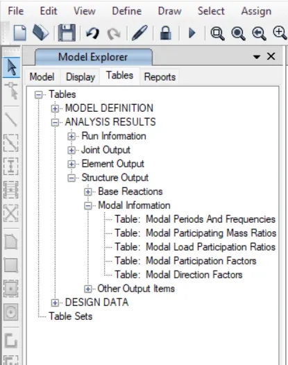
1. Now go to the model explorer and click on Tables Analysislsis results - > Structure output - > Model Information and then select model periods and frequencies
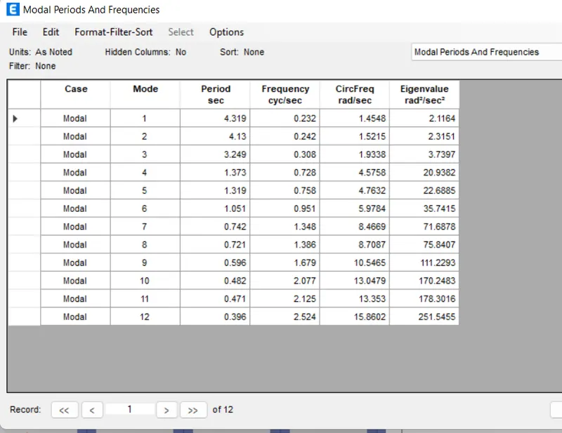
2. Time Periods Fundamental model mode1 Y direction and mode1 X direction are noted from the table and are as follows
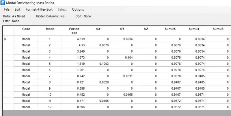
3. Go to Tables Analysislsis results - > Structure output - > Model Information and then select model participation pass mass ratio
4. Tx1 = 4.319s and Ty1 = 4.13s
5. From the table, the natural period for Mode1 and Mode 2 is shown below
Torsional Irregularity:
1. Tx1= 4.319s and Ty1= 4.13s and Txy1 = 3.249s.
2. So from the result it is clear that the torsion period is less than two translation periods as required by IS 1893 provision Table:5.
3. The natural period corresponding to the torsional mode of oscillation must be less than the two fundamental translational modes of oscillation along each principal direction.
Vertical Irregularity:
1. Check if the two provisions of clause 7 in Table 6 (shown below) of IS 1893 (part 1) – 2016, regarding vertical irregularity is satisfied
2. For mode1 and mode2, It's nearly 80% of the mass ratio which means it occupies 80% of the mass itself in the first mode. So, we don't need to add a second and third mode
Inter-storey Drift:
1. Check the if provision inter-story drift limitations in clause 7.11.1.1 are satisfied. Please note that this check is for Serviceability Limit State and hence it is for the situation when the structure is subjected to unfactored seismic base shear
2. The story drift serviceability base shear case is tabulated from the tool plots.
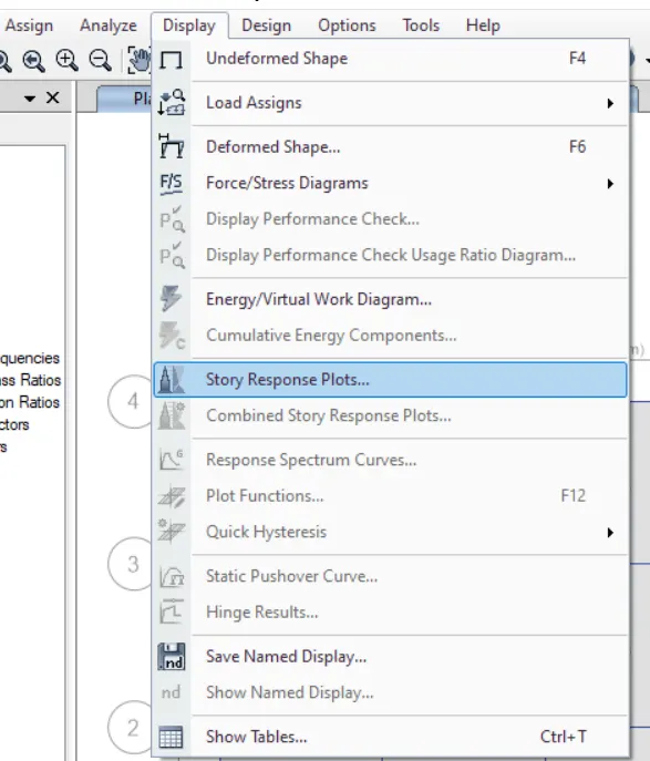
3. Go to display and then select story response plots.
4. Keeping load case to EQX and EQY, the maximum drift value noted for EQX is between 1.35 to 1.50 and EQY is between 1.40 to 1.60
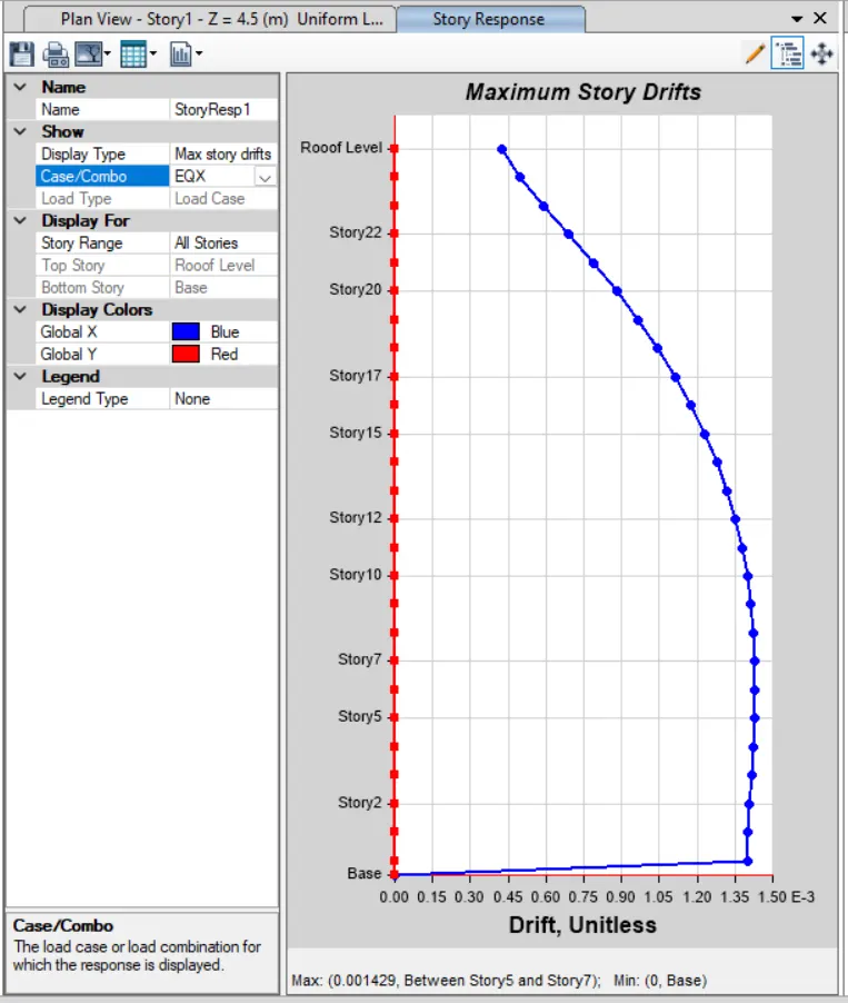
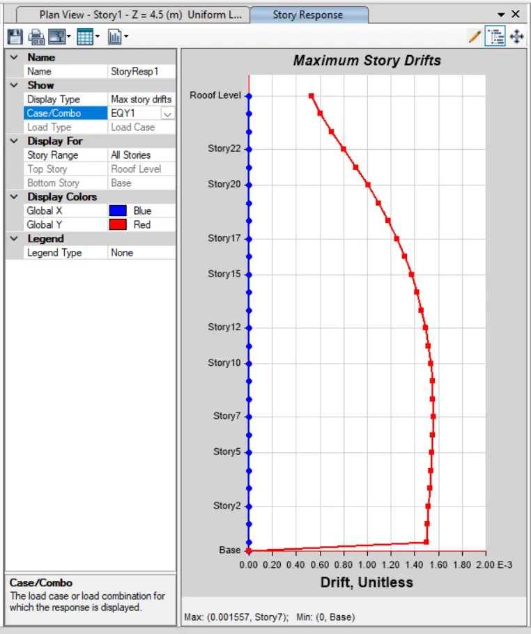
5. So as per the clause 7.11.1.1, the maximum inter-storey drift is limited to 0.004 for each story height, So it is satisfied
CONCLUSION:
Tmodelinging is completed and analysed in ETabs, The results are within the given range