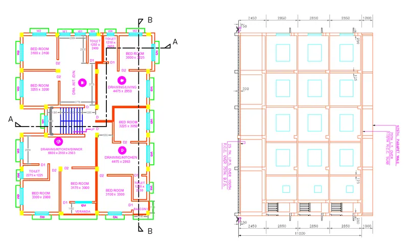
Creating a Layout, Section and Elevation with dimensions using AutoCad
Creating a Layout Plan, Section, and Elevation with dimensions using Autocad
1. SKETCHING LAYOUT PLAN:
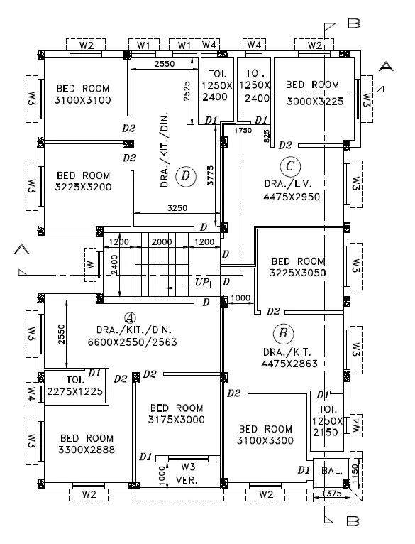
AIM:
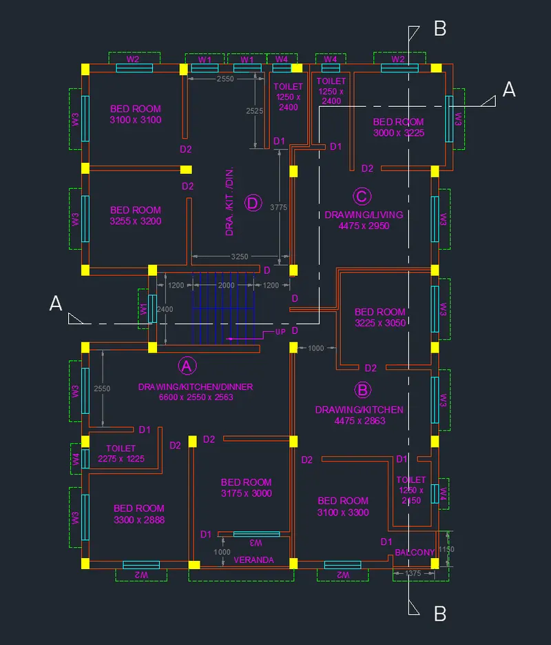
To draw the floor plan and give dimensions as per the drawing using Autocad
INTRODUCTION:
The floor plan is created in Autocad using primarily the XLine and other commands. The procedure of drawing is explained in detail step by step procedure with neat Sketches as shown below
COMMANDS USED:
1. Units
2. Limits
3. Layer Properties
4. XLine
5. Line
6. Trim
7. Offset
10. Rotate
11. Copy
12. Move
13. Text
14. Dimension
PROCEDURE:
1. Go to the application menu and select New
2. In the startup dialog box set Metric as the default settings
3. Type UN and set the units as Decimal and precision as 0.0
4. Set the units as Millimetres in the insertion scale
5. Type Limits in the command box and set the lower limit as 0,0 and upper limit as 10000,10000
6. Type Z enter for Zoom and A for Zoom all
Step 1:
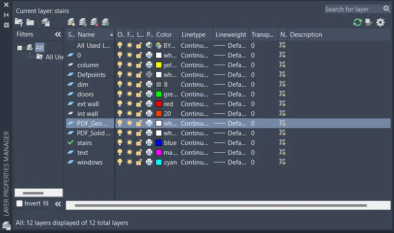
1. Select Layer properties by typing Layer in the command box
2. Click on a new layer to create the following layers (i.e., Doors and windows, External Wall, Internal Wall, Stairs, Furniture, Slab, Dimensions, and Text)
Step 2:
1. Select the Exterior wall as the default layer in the layer panel
2. Select the XLine tool by typing XL or XLine in the command box
3. Draw two lines ( i.e., horizontally and vertically ) both intersecting at a 90-degree point, and then press Esc to cancel the XLine
4. Select the Trim tool and trim the unnecessary lines and press enter
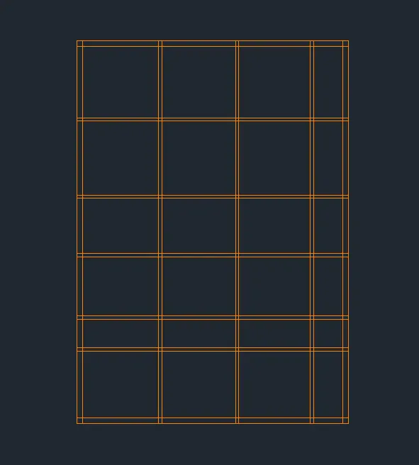
5. Select the Offset command and give the offset distance as 250
6. Select both the vertical and horizontal lines and Offset them inside
7. Similarly using the Offset command create the sketch that is shown in the figure below
3. Specify different colors for different layers to identify each layer easily and then close the layer properties manager
Step 3:
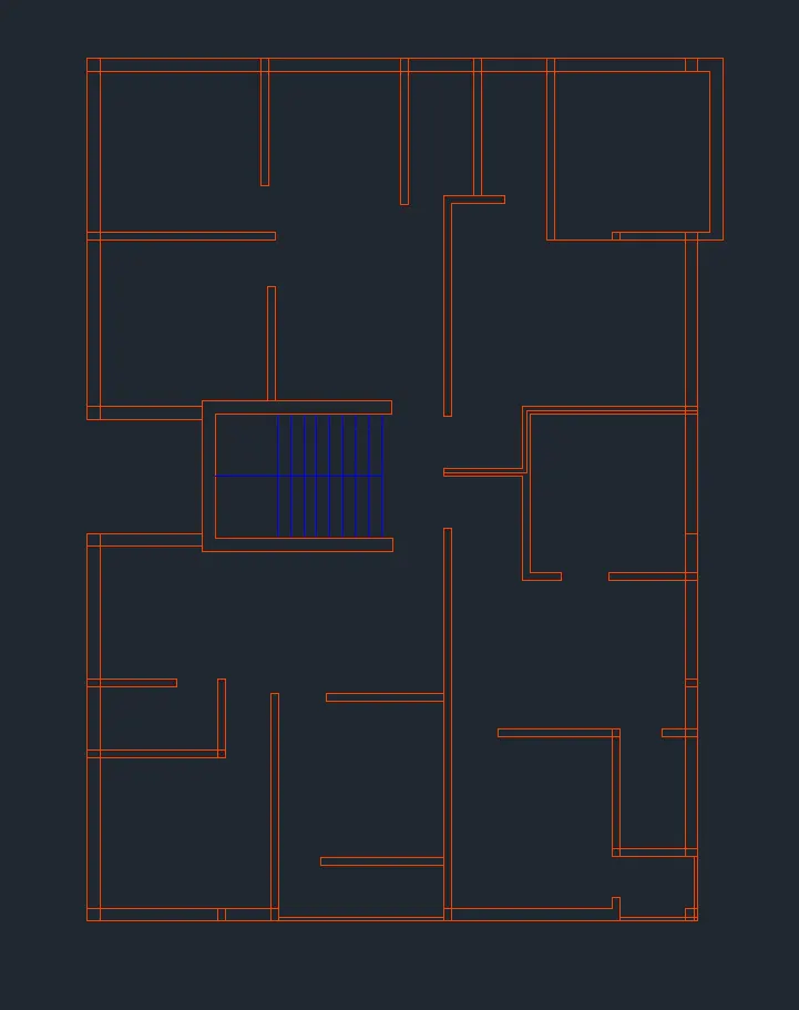
1. After Creating External walls, now we have to create internal walls using the Offset command
2. By using the Offset command create the internal walls with a thickness of 150mm
3. Specify the offset distance, select the line to offset, and click on the direction that we need to offset
4. Press Esc to cancel the line command
5. The new lines that we have drawn are selected and assigned to the internal wall layer
6. By using the Trim command and Extend Command, trim the unwanted lines and extend the lines that need to extend respectively
Step 4:
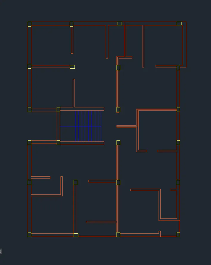
1. After creating external and internal walls, now we have to give column marking
2. Select the column layer in the layer properties
3. Select the Line tool by typing L or Line in the command box
4. Draw a column of dimension 250×350 and press Esc to cancel the Line Command
5. Select the Copy tool and copy the column created before to the desired locations as shown in the figure below
6. Select the Hatch tool by typing H or Hatch in the command box
7. Select Hatch pattern as solid, give hatch color as yellow and pick points inside the column
8. Select the Trim tool and trim the unnecessary lines
Step 5:
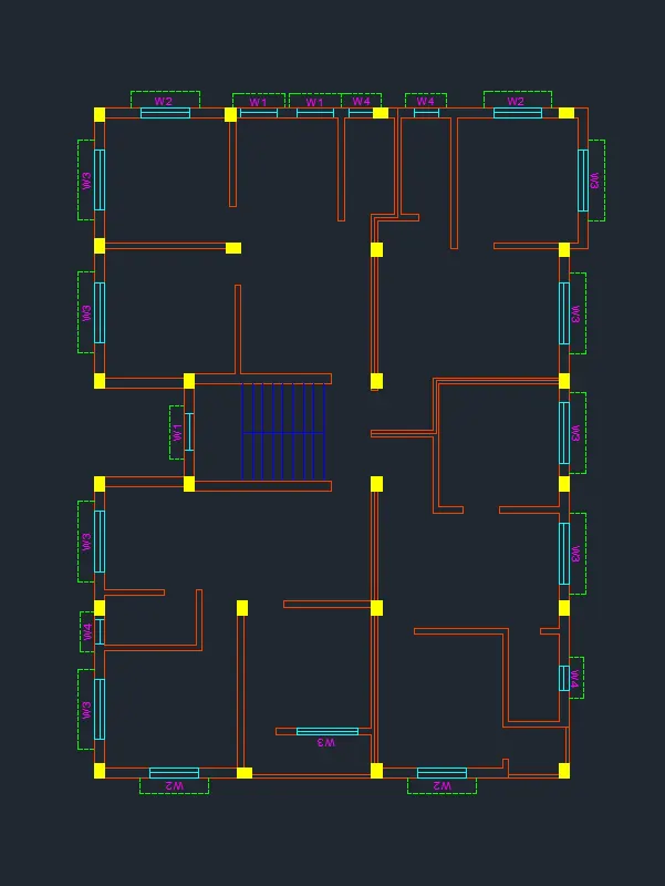
1. After creating Column markings, Now we have to draw doors and windows using the doors and windows layer
2. Select the Line tool by typing L or Line in the command box
3. Draw doors at the specified positions by using the Line tool and draw a swing of that door by using the Arc tool
4. Door D1 is created at the entrance with a width of 800
5. Door D2 is created at the entrance with a width of 900
6. Now we have to draw windows by using a door or window layer
7. Draw windows by using the Line command
8. Window W1 is created with a width of 900
9. Window W2 is created with a width of 1200
10. Window W3 is created with a width of 1500
11. Window W4 is created with a width of 600
12. After creating doors and windows, now we have to draw a staircase using staircase layer property
13. Select the Line tool and draw a length of 1800 at the entry point of the building
14. Select the Offset command and give the offset distance as 1200, then offset it through the desired side
15. Repeat Offset for distances 2000, 1200, and 250 to create the staircase
16. Draw a line through the midpoint of the lines created previously to divide the stairs and press Esc to cancel the line command
17. Select the offset tool and give the offset distance as 250mm and offset it through the desired side
18. By using the Line command, draw a line through the midpoint of the lines that we created earlier to divide the stairs
19. By using the Trim command, trim the unnecessary lines
Step 6:
1. Select the dimension and text layer as the default layer in the layer panel
2. Enter DS in the command box to open the dimension style manager dialog
3. Modify the dimensions as per the requirement
4. Change the color of the dimension and extension line as per the requirement
5. Under the text option, Change the text height to 100
6. click ok, then click set current and close the dimension style manager dialog box
7. Give dimensions and text as per the drawing and requirement using the Mtext command and Dimension Command
RESULT:
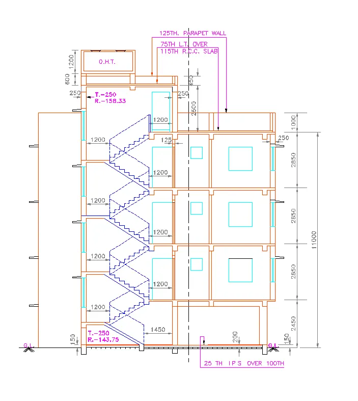
2. SKETCHING SECTION A-A :
AIM:
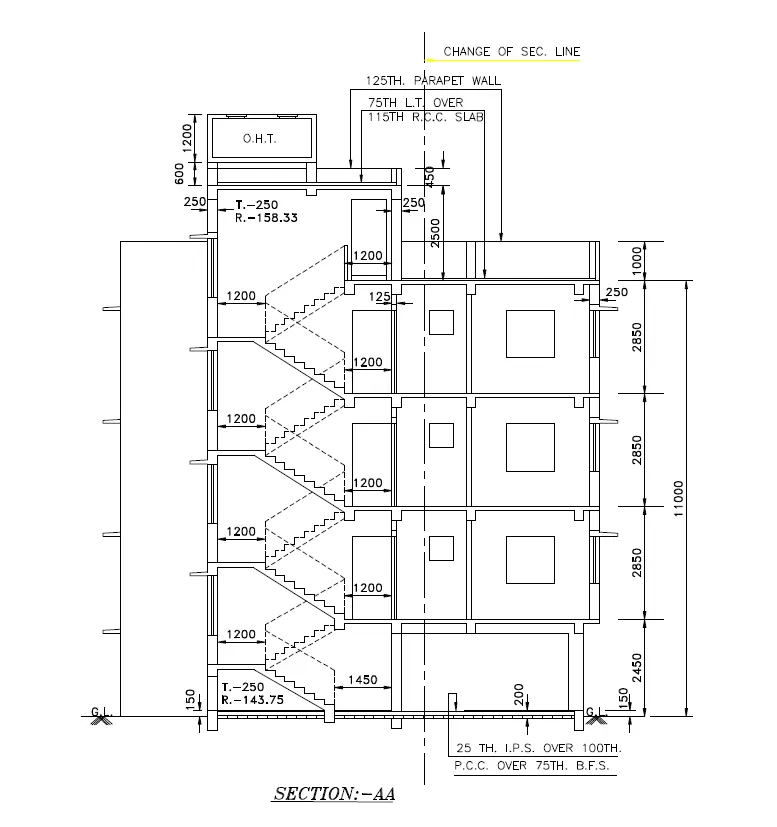
To draw Section A-A of the layout plan and give dimensions as per the drawing using Autocad
INTRODUCTION:
Section A-A is created in Autocad using primarily the Line and other commands. The procedure of drawing is explained in detail step by step procedure with neat Sketches as shown below
COMMANDS USED:
1. Units
2. Limits
3. Layer Properties
4. XLine
5. Line
6. Trim
7. Offset
10. Rotate
11. Copy
12. Move
13. Text
14. Dimension
PROCEDURE:
1. Go to the application menu and select New
2. In the startup dialog box set Metric as the default settings
3. Type UN and set the units as Decimal and precision as 0.0
4. Set the units as Millimetres in the insertion scale
5. Type Limits in the command box and set the lower limit as 0,0 and upper limit as 10000,10000
6. Type Z enter for Zoom and A for Zoom all
Step 1:
1. Select Layer properties by typing Layer in the command box
2. Click on a new layer to create the following layers (i.e., Doors and windows, External Wall, Internal Wall, Stairs, Furniture, Slab, Dimensions, and Text)
Step 2:
1. Select the XLine tool by typing XL or XLine in the command box
2. Draw vertical projection lines from the plan created and draw a horizontal line at a suitable distance
3. Select the Trim command and trim the unnecessary lines
4. Select the Offset tool by typing O or Offset in the command box
5. Create the offset lines according to the given drawing
6. The vertical X lines are offset to distances as per the given room dimensions and wall thickness
7. The horizontal X lines are offset to distances as per the given room dimensions and wall thickness
8. Select the Line Command by typing L or Line in the command box
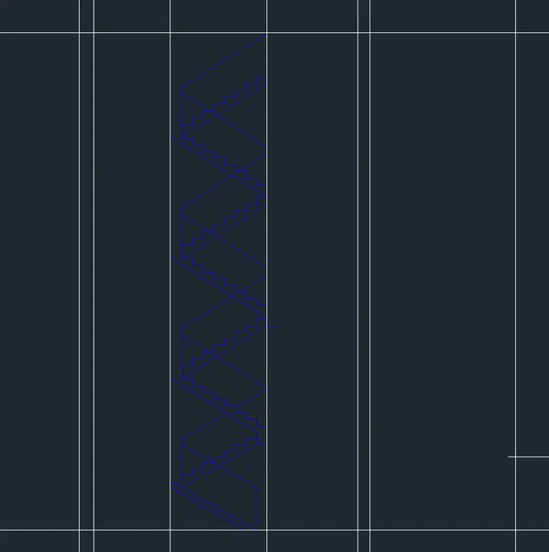
9. Draw stairs having a rise of 143.75 and thread of 250 and press Esc
10. Select the Copy tool and copy the stairs several times to create the flight of stairs as shown in the figure below
11. Select the flight of stairs created and assign it to the stairs layer
Step 3:
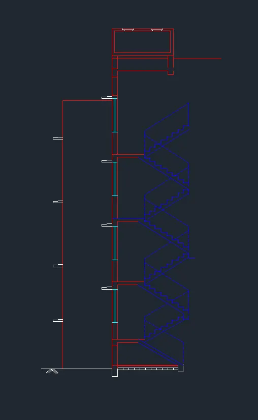
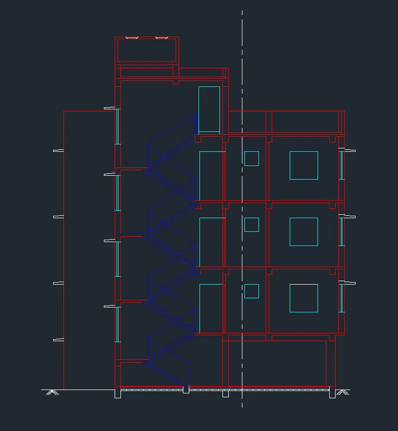
1. First we have to draw the line with the length of 8900mm horizontally forward
2. Next we have to draw another line from the previous line vertically with a length of 1mm
3. Next again draw the line from the previous line with the length of 11000mm horizontally backward from the previously drawn line.
4. Next draw the line from the first line and the last line we drew previously. Next, do the offset to the particular lines with the given offset values
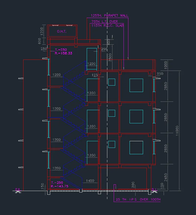
5. The inner wall offsets are 125mm and the outer wall thickness is 250mm. And the ground level thickness is 200mm and 150mm.
6. Next we have to draw the windows in their requires places in Ist. 2nd and 3rd floors Here
7. Next we have to draw the remaining parts, we draw the parapet wall and water tank (O.H.T) at the top of the building, Next, we draw the doors at their required places on the first second, and third floors.
8. Next remaining we draw the windows and sunshades in their particular places.
Step 4:
1. Select the Offset command by typing O or Offset in the command box
2. Create offsets according to the given drawing for the doors and windows
3. The height of the door is taken as 2100 and the height of the window is taken as 600 for smaller windows and 1200 for the bigger window
4. Select the Trim tool, trim the unnecessary lines, and press Esc
5. Select the Line tool by typing L or Line in the command box
6. Select Line type as ISO dash and draw the new section line
Step 5:
1. Select the dimension and text layer as the default layer in the layer panel
2. Enter DS in the command box to open the dimension style manager dialog
3. Modify the dimensions as per the requirement
4. Change the color of the dimension and extension line as per the requirement
5. Under the text option, Change the text height to 100
6. click ok, then click set current and close the dimension style manager dialog box
7. Give dimensions and text as per the drawing and requirement using the Mtext command and Dimension Command
RESULT:
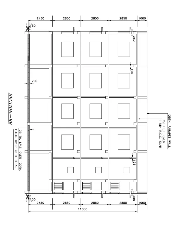
2. SKETCHING SECTION B-B:
AIM:
To draw Section A-A of the layout plan and give dimensions as per the drawing using Autocad
INTRODUCTION:
Section A-A is created in Autocad using primarily the Line and other commands. The procedure of drawing is explained in detail step by step procedure with neat Sketches as shown below
COMMANDS USED:
1. Units
2. Limits
3. Layer Properties
4. XLine
5. Line
6. Trim
7. Offset
10. Rotate
11. Copy
12. Move
13. Text
14. Dimension
PROCEDURE:
1. Go to the application menu and select New
2. In the startup dialog box set Metric as the default settings
3. Type UN and set the units as Decimal and precision as 0.0
4. Set the units as Millimetres in the insertion scale
5. Type Limits in the command box and set the lower limit as 0,0 and upper limit as 10000,10000
6. Type Z enter for Zoom and A for Zoom all
Step 1:
1. Select Layer properties by typing Layer in the command box
2. Click on a new layer to create the following layers (i.e., Doors and windows, External Wall, Internal Wall, Stairs, Furniture, Slab, Dimensions, and Text)
Step 2:
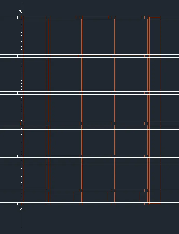
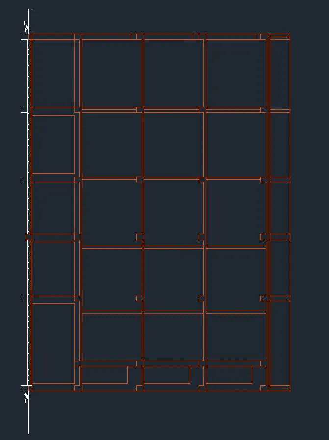
1. Select the XLine tool by typing XL or XLine in the command box
2. Draw Horizontal projection lines from the plan created and draw a horizontal line at a suitable distance
3. Select the Trim command and trim the unnecessary lines
4. Select the Offset tool by typing O or Offset in the command box
5. Create the offset lines according to the given drawing
6. The vertical X lines are offset to distances as per the given room dimensions and wall thickness
7. The horizontal X lines are offset to distances as per the given room dimensions and wall thickness
Step 3:
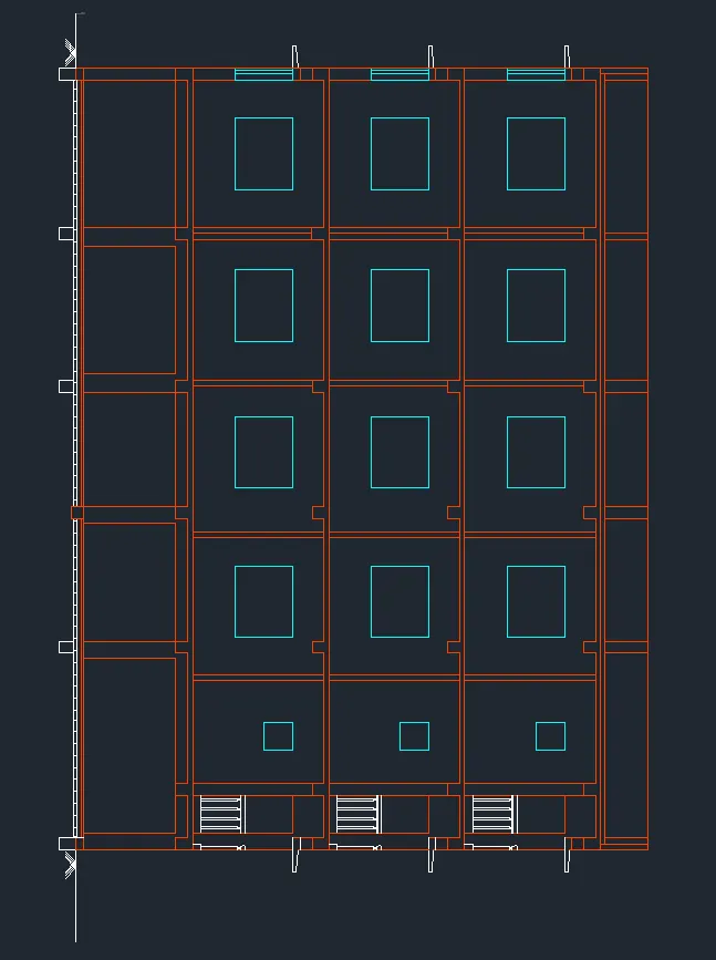
1. Select the Trim tool and trim the unnecessary lines
2. Select the Offset tool by typing O or Offset in the command box
3. Create offsets according to the given drawing for the doors and windows
4. The height of the door is taken as 2100, and the height of the window is taken as 600 for the smaller window and 1200 for the bigger window
5. Select the Trim tool by typing T or Trim in the command box
6. Trim the unnecessary lines and press Esc to cancel the Trim command
Step 4:
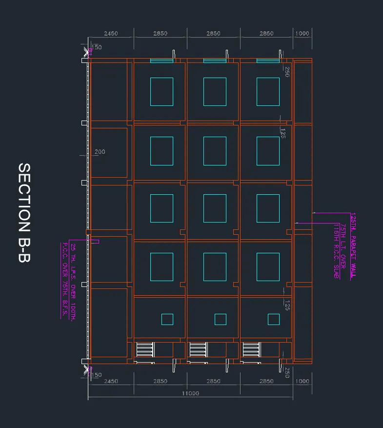
1. Select the dimension and text layer as the default layer in the layer panel
2. Enter DS in the command box to open the dimension style manager dialog
3. Modify the dimensions as per the requirement
4. Change the color of the dimension and extension line as per the requirement
5. Under the text option, Change the text height to 100
6. click ok, then click set current and close the dimension style manager dialog box
7. Give dimensions and text as per the drawing and requirement using the Mtext command and Dimension Command
RESULT: