Creation of Column Schedule and Drawing Template using AutoCad
1. TO CREATE A COLUMN SCHEDULE
AIM:
To Create a Column Schedule with the help of lines and to insert text with the help of the Dtext command or Single Line Text.
INTRODUCTION:
Structural columns are identified in a column schedule by intersecting grid lines and by their top and bottom constraints and offsets. They are placed into the column schedules according to these identifications.
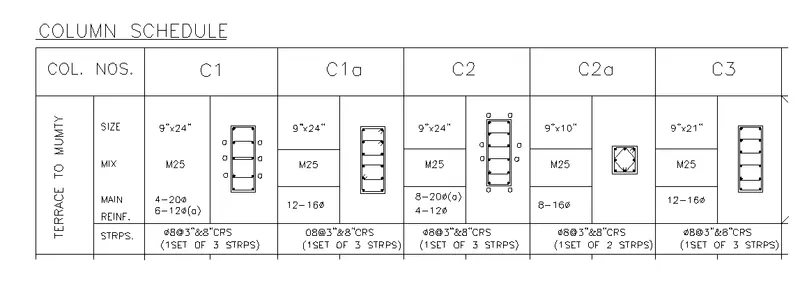
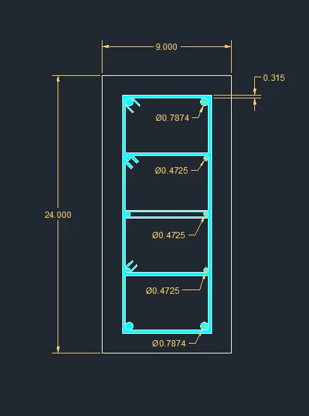
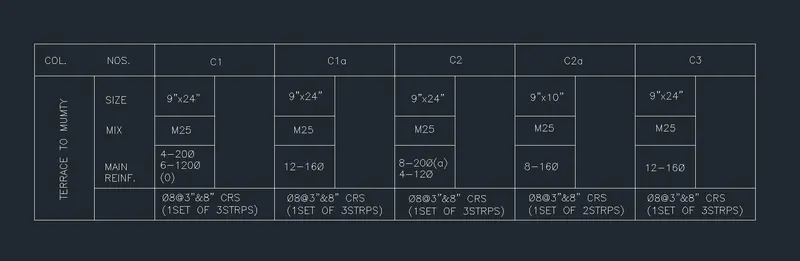
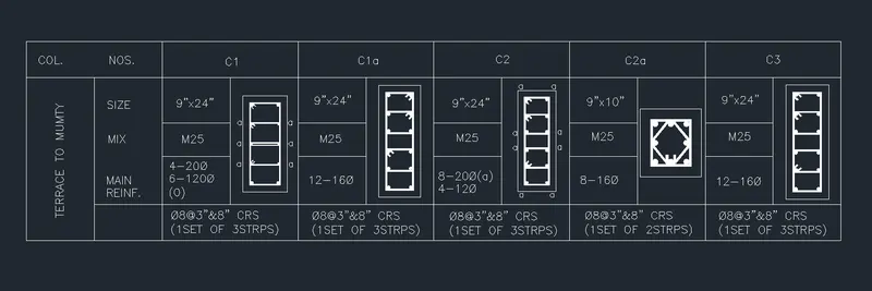
1. Column C1 is provided with 4 bars of 20 mm dia, and 6 bars of 12 mm dia. The 12 mm dia bars are marked with 'a.
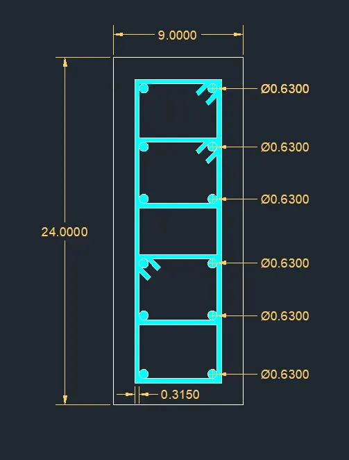
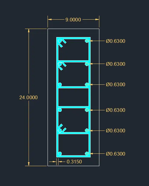
2. Column C1a and Column C3 are provided with 12 bars of 16 mm dia bars.
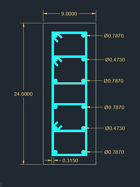
3. Column C2 is provided with 8 bars of 20 mm dia and 4 bars of 12 mm dia. The 20 mm dia bars are marked with 'a'.
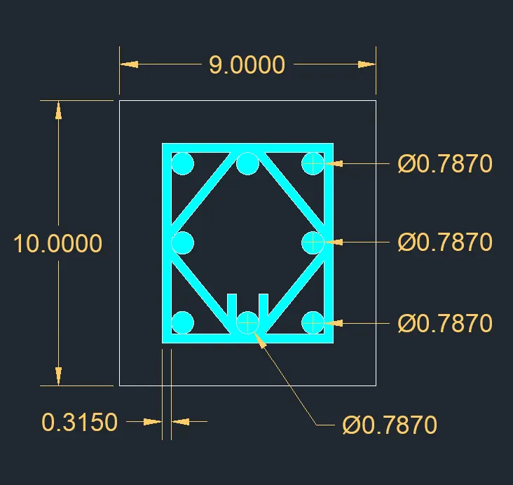
4. Column C2a is provided with 8 bars of 16 mm dia.
5. All columns are provided with 8 mm dia stirrups with 3" spacing cc near the ends and 8" cc in mid-length.
6. The clear cover for all the columns is assumed to be 1.5" (approx 40 mm). As per IS 256, the minimum cover to the column should not be less than 40 mm
Commands Used:
1. Units
2. Limits
3. Zoom
4. Line
5. Offset
6. Trim
7. Circle
8. Copy
9. Move
10. Rotate
11. Text
12. Dimension
PROCEDURE:
1. Open new page Select Architectural Precision as 0-0 1/256" and Apply Procedure
2. Type Limits in tho Command box and set the limits as 0,0 and 100',100'
3. Type 'Z' enter for Zoom and then type 'A' for Zoom all
Step 1:
We have to draw the column C1 as shown in the figure below by using all the dimensions and stirrup details with reinforcement
Step 2:
Similarly, We have to draw the column C1a as shown in the figure below by using all the dimensions and stirrup details with reinforcement
Step 3:
We have to draw Column C2 as shown in the figure below
Step 4:
Similarly, We have to draw Column C2a as shown in the figure below
Step 5:
We have to draw the column C3 as shown in the figure below by using all the dimensions and stirrup details with reinforcement
Step 6:
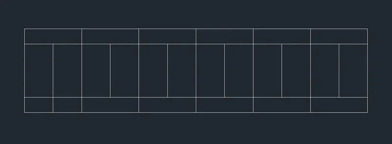
1. To create a column schedule by mentioning reinforcement details and stirrup details
2. Draw a table with the help of line command and trim the unnecessary extra lines and make a table
Step 7:
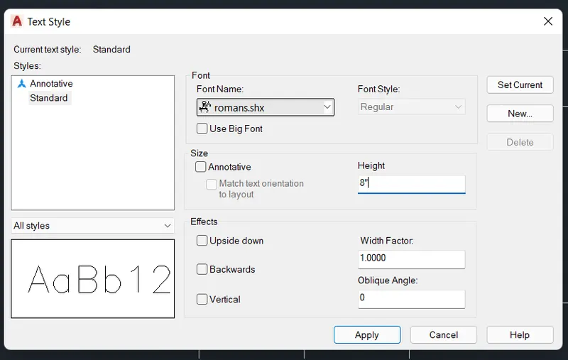
1. Open Text style dialog box and select the text style font as roman.shs and text height as 8"
2. Type all the necessary texts as shown in the figure below
Step 8:
1. After giving text details, now move the columns one by one to their respective places as shown in the figure below
RESULT:
2. TO CREATE A WINDOW SCHEDULE:
AIM:
To create a window schedule by using the line tool and text command
INTRODUCTION:
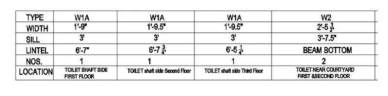
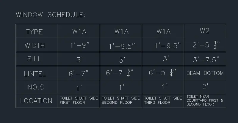
The table contains all the necessary window schedules such as width, sill, lintel height, and their numbers and respective location for different types of beams.
Commands Used:
1. Units
2. Limits
3. Zoom
4. Line
5. Offset
6. Trim
7. Text
PROCEDURE:
1. Open new page Select Architectural Precision as 0-0 1/256" and Apply Procedure
2. Type Limits in tho Command box and set the limits as 0,0 and 100',100'
3. Type 'Z' enter for Zoom and then type 'A' for Zoom all
Step 1:
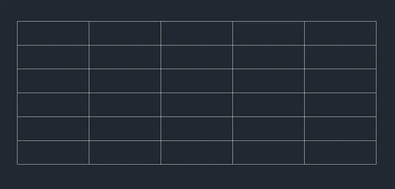
1. Select the Line command and create a table of 6×5 (i.e. 6 rows and 5 columns) as shown in the figure below
Step 2:
1. Open Text style dialog box and select the text style font as roman.shs and text height as 8"
2. Type all the necessary texts by using Single Line text or Multi-Line text as shown in the figure below
RESULT:
3. TO CREATE A DRAWING TEMPLATE:

AIM:
To create a Drawing template by using all the necessary data
Commands Used:
1. Units
2. Limits
3. Zoom
4. Line
5. Offset
6. Trim
7. Text
PROCEDURE:
1. Open new page Select Architectural Precision as 0-0 1/256" and Apply Procedure
2. Type Limits in tho Command box and set the limits as 0,0 and 100',100'
3. Type 'Z' enter for Zoom and then type 'A' for Zoom all
Step 1:
1. Select the Line command and make a table as shown in the figure below
2. Open Text style dialog box and select the text style font as roman.shs and text height as 8"
3. Type all the necessary texts by using Single Line text or Multi-Line text as shown in the figure below
RESULT:

3. TO CREATE THE LIST OF DRAWING SCHEDULE
AIM:
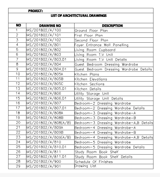
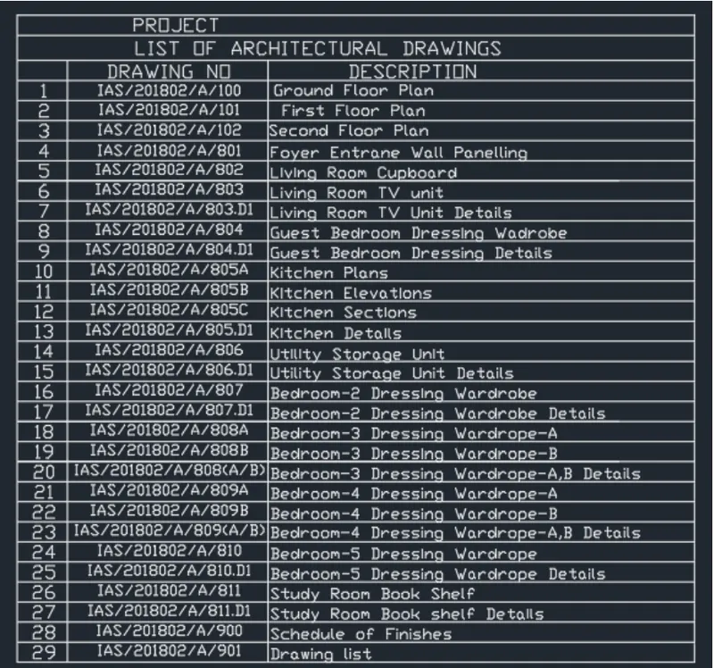
To create the list of architectural drawings with drawing number description
Commands Used:
1. Units
2. Limits
3. Zoom
4. Line
5. Offset
6. Trim
7. Text
PROCEDURE:
1. Open new page Select Architectural Precision as 0-0 1/256" and Apply Procedure
2. Type Limits in tho Command box and set the limits as 0,0 and 100',100'
3. Type 'Z' enter for Zoom and then type 'A' for Zoom all
Step 1:
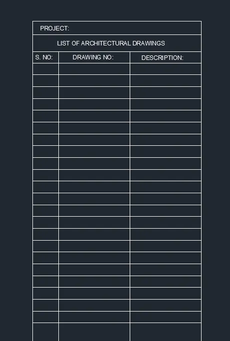
1. Create a table by using line command or table section
2. Make a table of 3× 31 (i.e. 3 rows and 31 columns) as shown in the figure below
Step 2:
1. Open Text style dialog box and select the text style font as roman.shs and text height as 8"
3. Type all the necessary texts by using Single Line text or Multi-Line text such as serial number, drawing number, and description as shown in the figure below
RESULT:
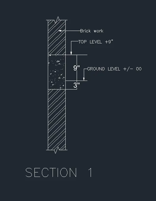
5. TO CREATE THE BEAM DETAILS
AIM:
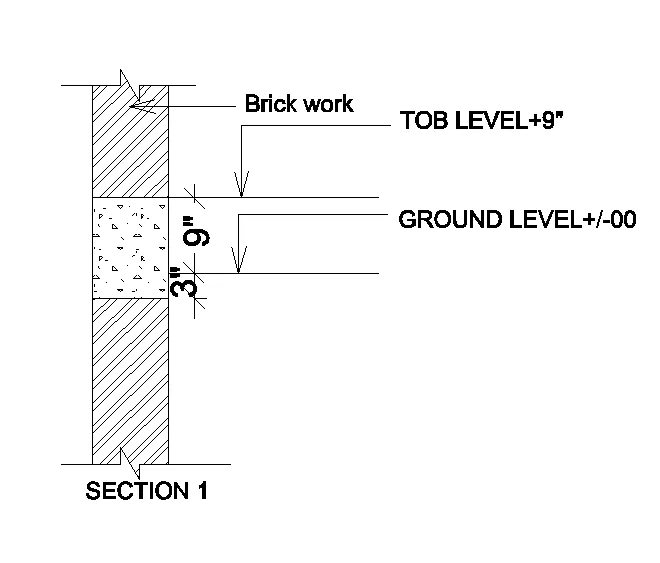
To create the beam detail and provide text for top-level and ground level as per drawing
Commands Used:
1. Units
2. Limits
3. Zoom
4. Line
5. Break Line
6. Offset
7. Trim
8. Hatch
9. Text
10. Dimension
PROCEDURE:
1. Open new page Select Architectural Precision as 0-0 1/256" and Apply Procedure
2. Type Limits in tho Command box and set the limits as 0,0 and 100',100'
3. Type 'Z' enter for Zoom and then type 'A' for Zoom all
Step 1:
1. Select the 'Line' command by typing Line in the command box
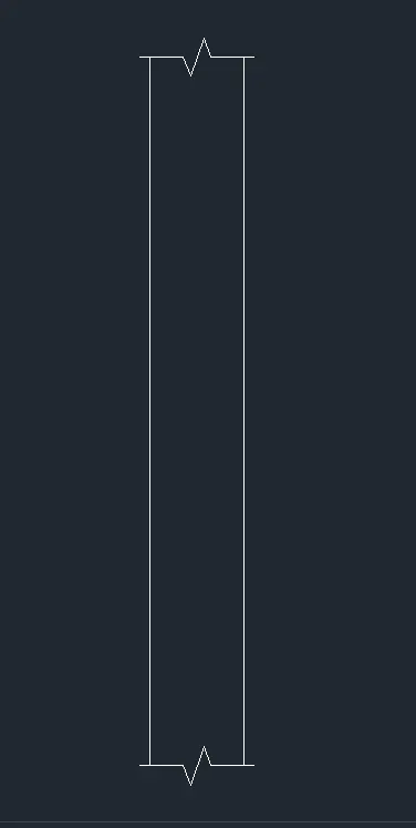
2. Make two parallel lines 45" long at a distance of 6" from each other
3. By using the 'Breakline' command, make a brake line at the top and bottom as shown in the figure below
Step 2:
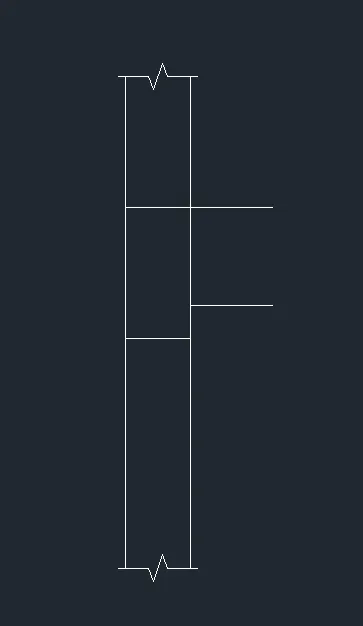
1. Take the Offest command by typing 'O' or Offset in the command box
2. Give offset distance as 12" and offset the top line to the -Y direction as shown in the figure below
3. Select the offset command again, now offset the previous line through -Y direction by giving Offset distance as 9"
4. Similarly, now offset the previous line through -Y direction again by giving Offset distance as 3"
Step 3:
1. Select Hatch command or by typing 'Hatch' in the command box
2. Now give the hatching of brickwork and concrete as shown in the figure below
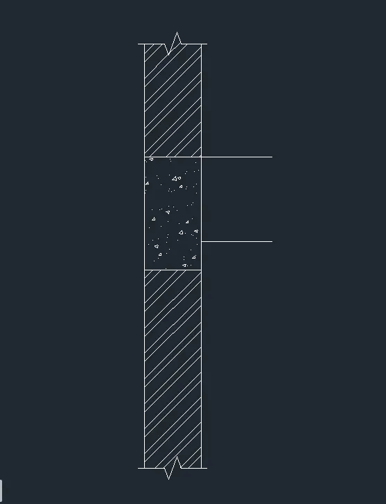
Step 4:
1. Give dimensions as per drawing by typing 'Dim' in the command
2. Open Text style dialog box and select the text style font as roman.shs and text height as 8"
3. Type all the necessary texts by using Single Line text or Multi-Line text
RESULT: