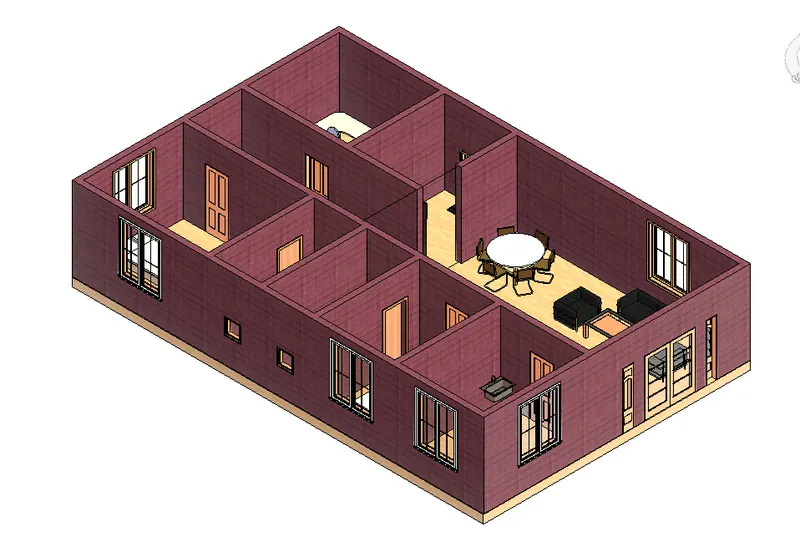
Creating Walls, Partition walls and Floors for a residential layout using REVIT
Creating Walls, Partition Walls, and Floors for a residential layout using REVIT
1) Use the project file created from Week 2. Use it for this assignment. Based on your layout from week 2, use the floor tool under the architecture tab and select the floor with appropriate material and thickness using the property browser to create a layout on the Ground floor Level. Align the floor plan with grids created from week 2
AIM:
To create a floor plan using the architectural tab and give appropriate material and thickness using the property browser
INTRODUCTION:
Floors in Revit are three-dimensional objects, and they have instance and type properties, just like other elements in Revit. These properties control the structure of the floor along with how the floor should be constructed.
In this project, we have to create a floor for the week 2 drawing using an architectural tab. After creating the floor, we have to give appropriate thickness, and material using the property browser and then align the floor plan with grids
PROCEDURE:
Step 1:
1. First open the REVIT software and click on Load to open the previous drawing
2. On the next page, go to the Architectural tab and select floor tool
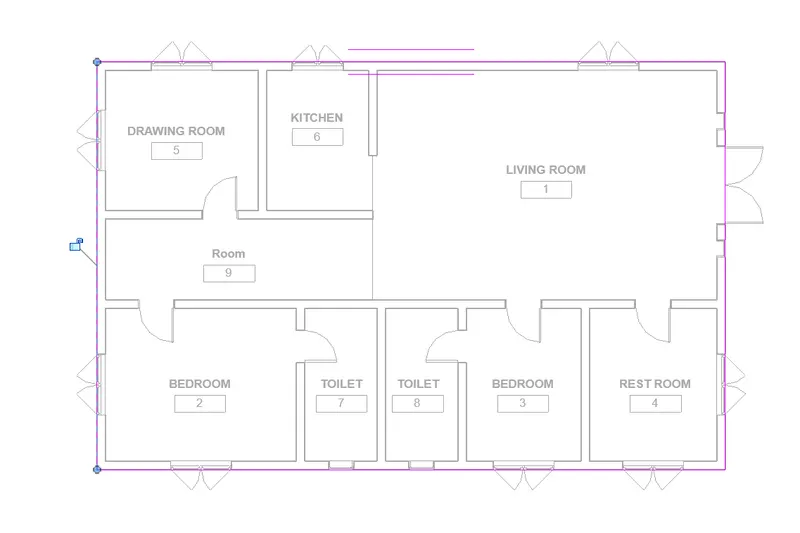
3. Create the floor by connecting the exterior walls as shown in the figure below.
Step 2:
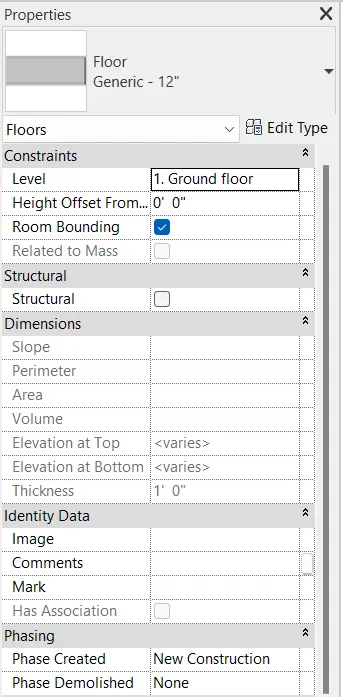
1. After Creating the floor, go to Property browser and click on edit type
2. We can access the properties of the floor in the edit type option
Step 3:
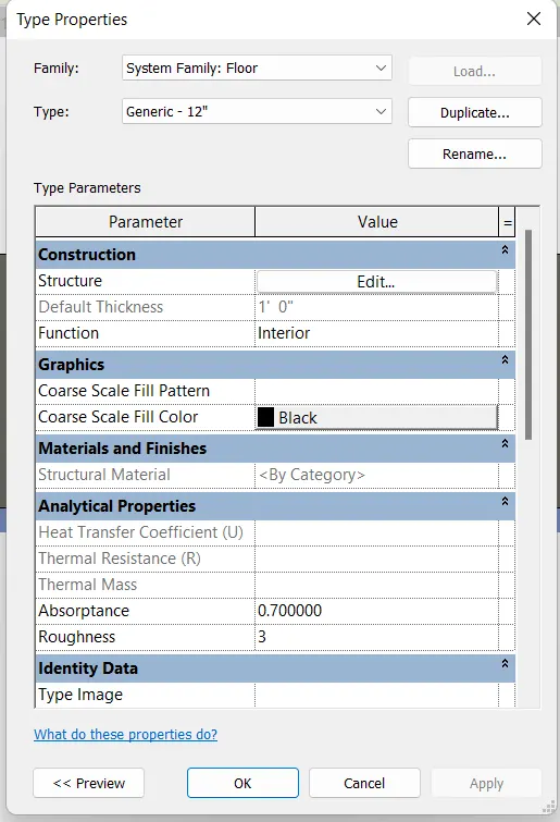
1. Create the duplicate floor and give the name as Generic 12" Floor
Step 4:
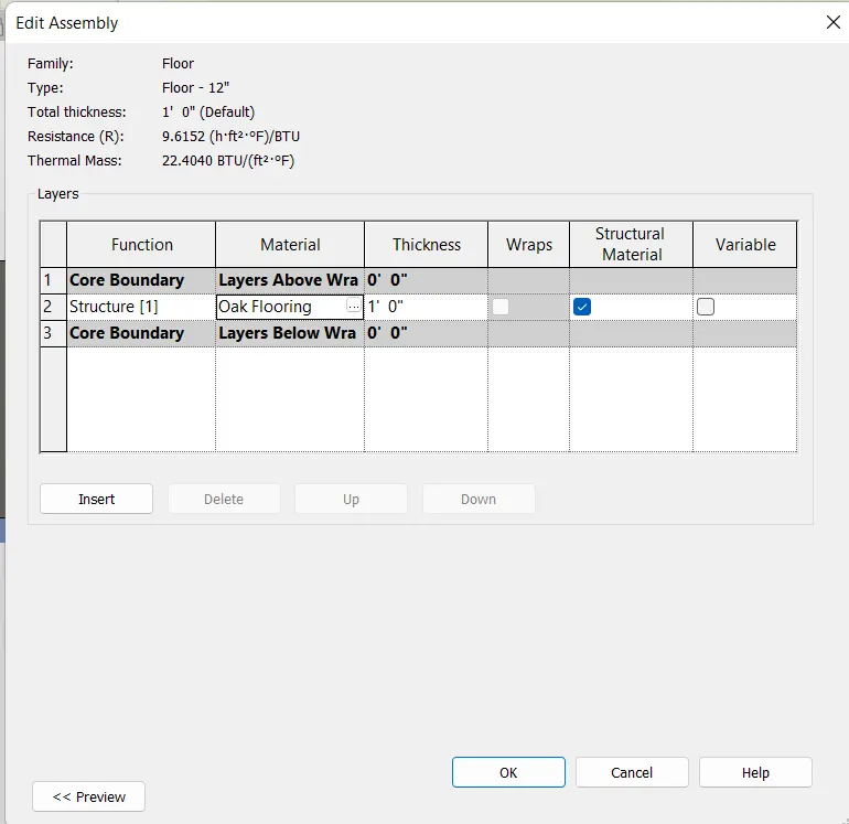
1. In the structure tab, click on the edit option to open the edited assembly
2. Give the thickness of the floor as 1'
3. In the material section, select the material as oak flooring
Step 5:
1. Click on Ok and then click Apply to change the material and thickness
2. After Creating the floor with appropriate thickness and material, it will apply to the selected floor as shown in the figure below 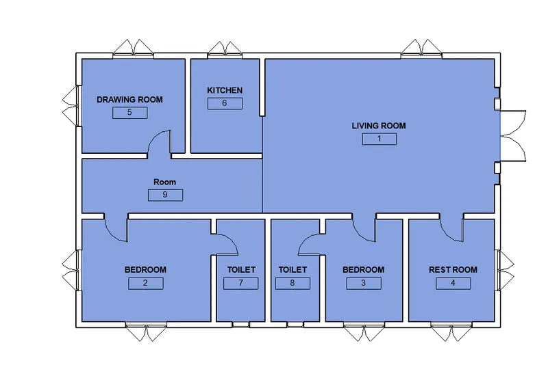
Step 6:
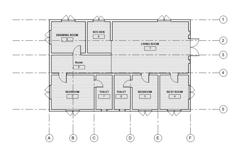
1. After creating the floor with appropriate thickness and material, now we have to align the grids to the floor plan
2. Go to the Architectural tab and select the grid tool
3. Select create line option and create the grids along with the floor plan
4. Align transverse and horizontal grids through the floor plan as shown in the figure below
RESULT:
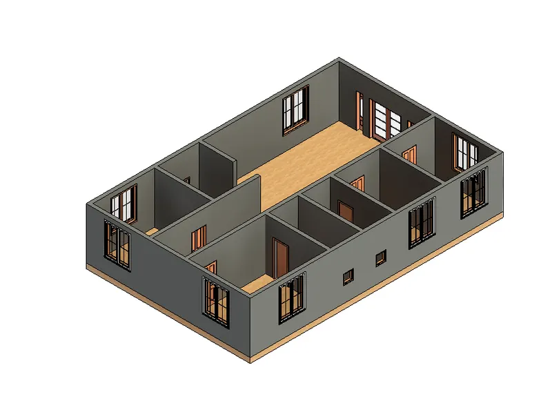
1. The floor has been successfully created to the week 2 plan with appropriate material and thickness
2. After creating the floor, the grids have been aligned to the floor plan successfully
2) Add walls based on the floor layout. Pick lines or use the draw tool to modify the boundary of walls. Use the property browser to select the appropriate material and thickness for walls. After creating the walls verify using the property browser to see if the top and bottom of the walls are constrained.
a. Based on your observation, what is beneficial for connecting walls with associated levels rather than being Unconnected
b. Which option is convenient for modeling walls, By Height or By Depth?
AIM:
To create walls and need to apply the material and thickness using the property browser
INTRODUCTION:
In this project, we have to create the walls for the floor plan and give appropriate thickness and material for the walls using the property browser
Whenever we want to create a new wall, we will have to start by duplicating an existing one. This is made by clicking on "Edit type" under the wall selector in the properties panel and later in "Duplicate".
PROCEDURE:
Step 1:
1. Go to the floor plan and select the walls that we want to give thickness and material
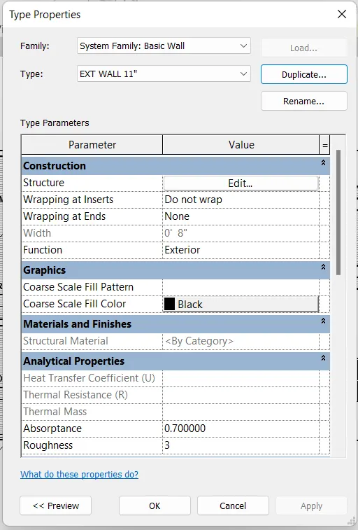
2. Go to Property browser and click on edit type to open type properties
3. In the Type Properties dialog box, create a duplicate and rename it as Exterior wall 11"
Step 2:
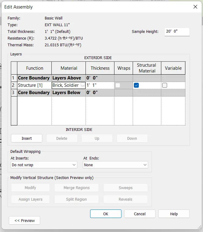
1. In the Type parameters section, click on edit under the structure tab
2. In the thickness box, Change the thickness of the wall to 11"
3. In the structure box, click on a category to open the material browser
Step 3:
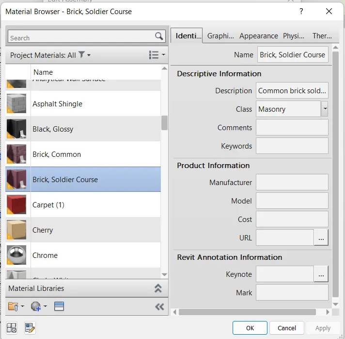
1. Select the wall material as Brick, Soldier Course
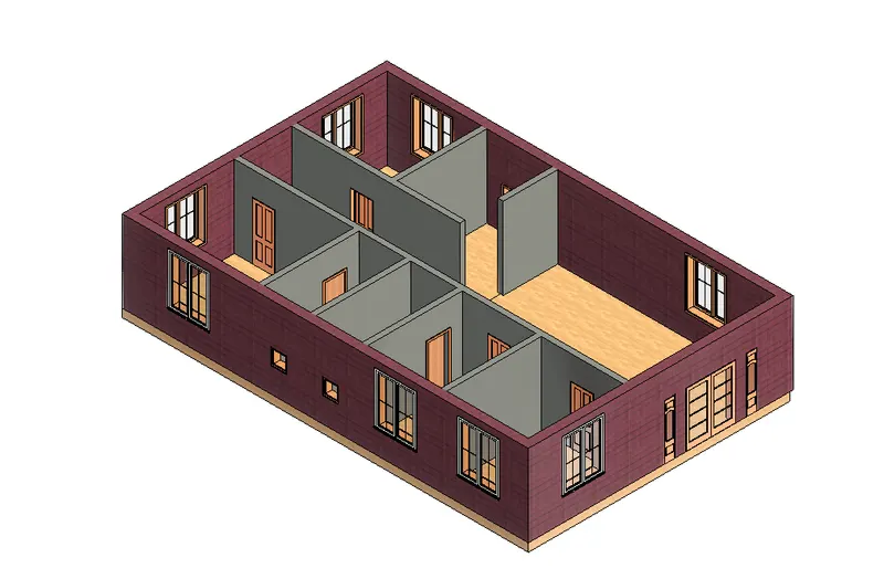
2. Click on Ok and Press apply to change the Thickness and Material of the walls
Step 4:
1. Go to the floor plan and select the interior walls that we want to give thickness and material
2. Go to Property browser and click on edit type to open type properties
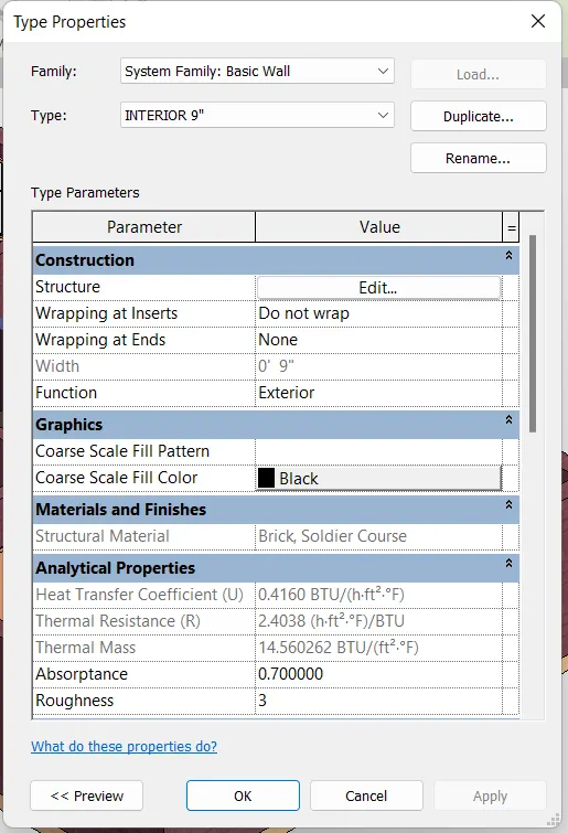
3. In the Type Properties dialog box, create a duplicate and rename it as Interior wall 9"
Step 5:
1. In the Type parameters section, click on edit under the structure tab
2. In the thickness box, Change the thickness of the wall to 9"
3. In the structure box, click on a category to open the material browser
Step 6:
1. Select the wall material as Brick, Soldier Course
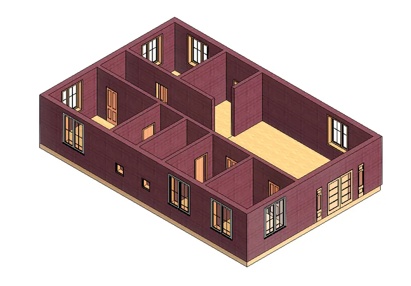
2. Click on Ok and Press apply to change the Thickness and Material of the walls
Step 7:
a. Based on your observation, what is beneficial for connecting walls with associated levels rather than being Unconnected
1. The initial constraints of a wall are the constraints we set in the properties browser
2. Base constraint is where the base of the wall is a constraint to, this is the level on which we placed the wall.
3. Top constraint is where the top of the wall is a constraint to. If we set this on unconnected, we specify the wall's unconnected height.
4. Alternatively we can specify a level as the top constraint, the wall will then run-up to this level.
- Additionally you can specify an offset for both the base and top constraints. This vertical distance is added or subtracted from the specified constraints. These offsets are ignored for attached or unconnected parts of a wall.
Attaching Top/Base:
- With the attach top/base function we can attach walls to other elements like roofs, floors, ceilings, or other elements in the same vertical plane. The effect is, that if we change the height of those elements or the shape the wall will follow automatically.
b. Which option is convenient for modeling walls, By Height or By Depth?
By using Height Option:
1. If we connect a wall's height to a level, REVIT will understand that when a level changes its height, the wall needs to change.
2. Thus, it will automatically coordinate the wall's height to the level's height.
3. If we do not wish to connect a wall to a level, select Unconnected, which allows you to specify a value for Height.
By using the Depth option:
1. When we create a wall in a plan view, the Base Constraint is the level associated with the view.
2. When we create a wall in a 3D view, use Level on the Options Bar to specify the level to use for the wall's Base Constraint value.
3. When we use Depth on the Options Bar, use a structural plan to see the walls extending downward from the current level, or modify the view range of a floor plan to make them visible.
RESULT:
The walls have been successfully added to the floor plan with appropriate material and thickness.
a) According to my observation, the Connected wall is beneficial rather than unconnected
b) Similarly, the height option is better and more convenient for modeling rather than the depth option because it does not disturb the base level
3) Copy the model elements ( wall, floor ) modeled to Ground Floor Level and paste it aligned to First Floor Level. Use modify tab to utilize copy and paste options to align elements to a different level
AIM:
To Copy the model elements from the ground floor level and paste them aligned to the first-floor level using modify tab
INTRODUCTION:
The Copy to Clipboard tool copies one or more elements to the clipboard. We can then use the Paste from Clipboard or Paste Aligned tools to paste copies of the elements in the drawing or another project.
PROCEDURE:
Step 1:
1. Go to floor plan and select the ground level plan using the project browser
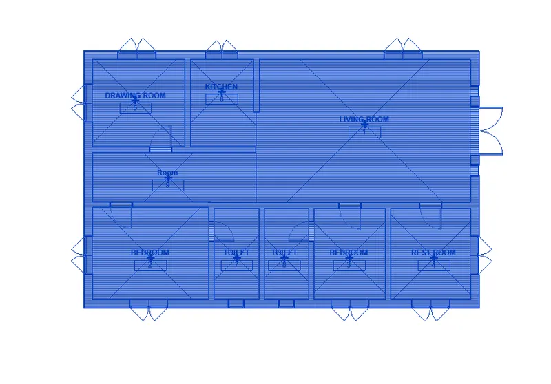
2. Then Select the total ground floor and click on copy clipboard in modify tab
Step 2:
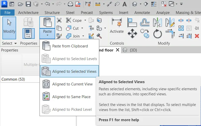
1. After Copying the ground floor, go to the paste option in modify tab
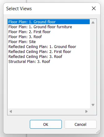
2. Select the paste option as aligned to selected views
Step 3:
1. Select the aligned paste location as the First floor
2. In this view, we need to select the Floor plan 2. First floor
Step 4:
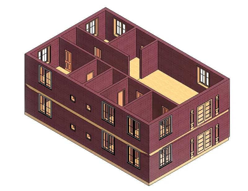
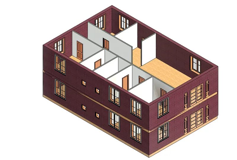
1. Finally the elements are aligned to the different levels as shown in the figure below
RESULT:
The Ground Floor elements are successfully aligned to the First Floor using the copy and paste option in modify tab
4) Use interior partition walls to create separate rooms within your residential unit. The model must include the following rooms
a. Living Room/ Drawing Room ( 15’ X 18’)
b. Dining Room (9’ X 11’)
c. Bed Room ( 9’ X 12’ and 15’ X 11’)
d. Rest Room ( 10’ X 12’ )
e. Kitchen (8’ X 10’)
AIM:
To create the separate rooms for residential building units using interior partition walls
INTRODUCTION:
A partition wall may be described as a wall or separation constructed up of bricks, studding, glass, or other such types of material and utilized to separate one part of a room from another part of a room. Fixed type. If partition walls are load-bearing then it is called 'internal walls'.
PROCEDURE:
Step 1:
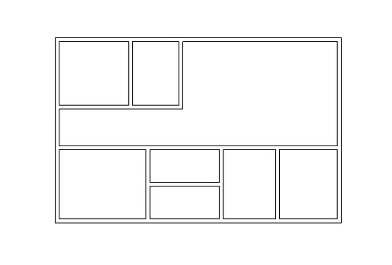
1. First we have to create the separate rooms for the residential building unit
2. Go to the Architectural tab, Create the walls to define different rooms
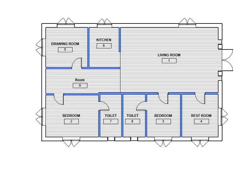
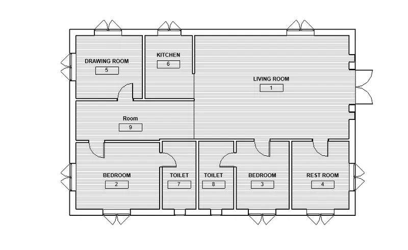
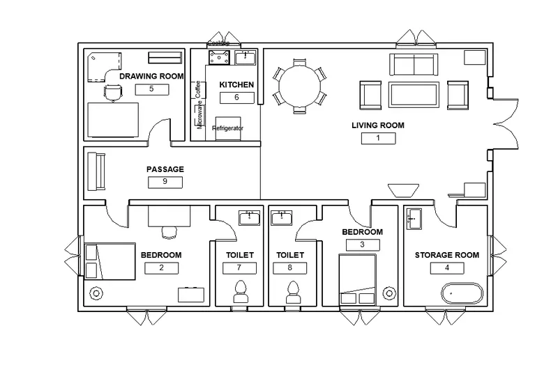
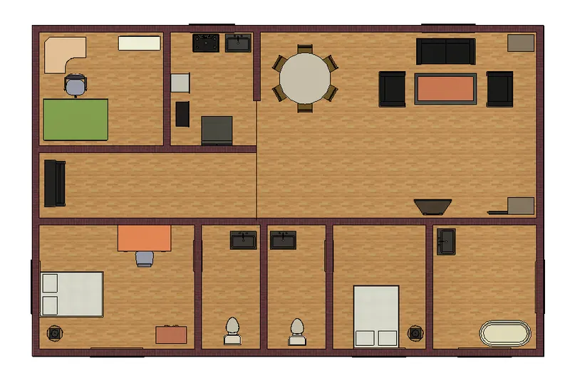
3. The model is included with the Living room, Dining room, Bedrooms, Restroom, Kitchen, and with the addition of a Drawing room and toilets
Step 2:
1. Specify the room tags for identifying the Rooms
2. After Creating the residential plan, select the interior walls as shown in the figure below
Step 3:
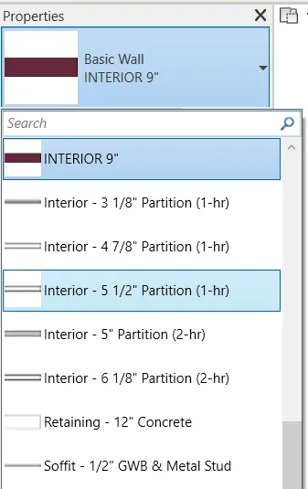
1. After Selecting the interior walls, go to Properties browser
2. Select the wall type as Interior 5 1/2" Partition (1-hr)
Step 4:
1. The Interior partition walls are created as shown in the figure below
RESULT:
The interior partition walls are successfully created for the residential building unit.
5) Based on the week 2 assignment, the components to be included in a residential unit were inserted into the Revit file. Place these components in appropriate locations to add details to your residential model
a. Place Doors and windows on the wall at appropriate locations
b. The Living Room must include a furniture set, couch table, TV desk, and shelf cabinets
c. The Dining Room must include a table and chairs serving the purpose of eating
d. Bed Room must include a bed set, shelf, lighting, and individual study desk and chair
e. Restroom should include a bathtub and plumbing fixtures discussed in class
f. Kitchen should include countertops, gas stove cabinet, and shelves to store food items
g. The wash/storage room can include washing machines and shelves to store clothes
AIM:
To Insert the components in appropriate locations to add details to the residential model, based on the week 2 assignment
INTRODUCTION:
Components are instances of loadable families and are hosted by other elements, which are instances of system families.
In Revit, components are used to model building elements that are usually delivered and installed on-site, such as doors, windows, furniture, and so on.
For example, a door is hosted by a wall, while a freestanding component such as a desk is hosted by a floor or a level.
PROCEDURE:
Step 1: (Doors and Windows)
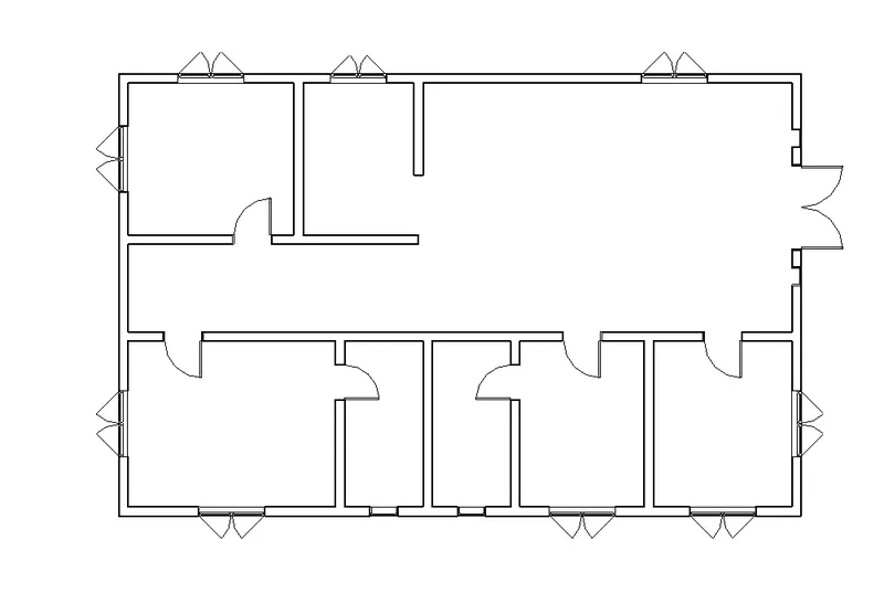
1. First we need to insert the doors and windows for the residential unit
2. Go to the Architectural tab and select the Load Component option
3. In that tab, select load family and select the required components such as Doors and windows
4. After loading the components, Place the doors and windows in the desired locations
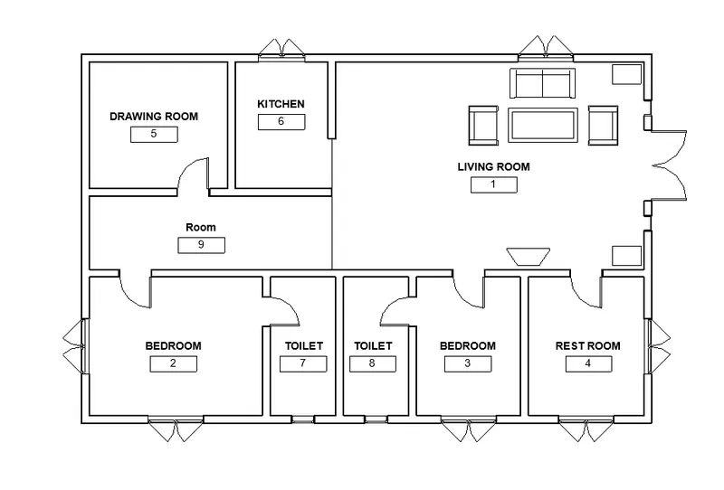
Step 2: (Living Room)
1. Then we need to insert the furniture components into the hall
2. Go to the Architectural tab and select the Load Component option
3. In that tab, select load family (Libraries > US > Furniture) and select the required components such as sofa set, couch, TV desk, and Self cabinets
4. After loading the components, Go to the Architectural tab and select the load components option
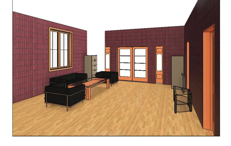
5. Place the Furniture components for the hall in the desired locations as shown in the figure below
Step 3: (Dining Room)
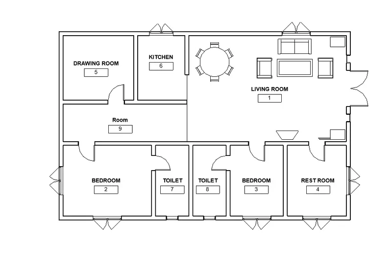
1. Now, we need to insert the furniture components in the Dinning room
2. Go to the Architectural tab and select the Load Component option
3. In that tab, select load family (Libraries > US > Furniture) and select the required components such as Dinning table
4. After loading the components, Go to the Architectural tab and select the load components option
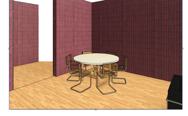
5. Place the Furniture components for Dinning room in the desired locations as shown in the figure below
Step 4: (Bedrooms)
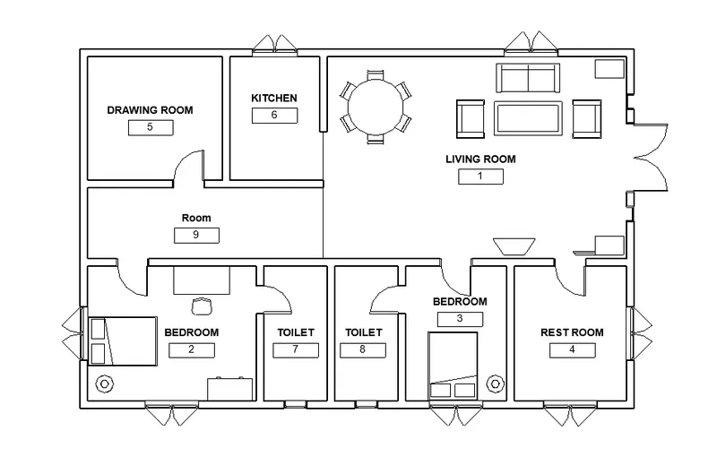
1. Now, we need to insert the furniture components into the Bedrooms
2. Go to the Architectural tab and select the Load Component option
3. In that tab, select load family (Libraries > US > Furniture) and select the required components such as Bed, Desk, Chair, Cabinets, and lighting
4. After loading the components, Go to the Architectural tab and select the load components option
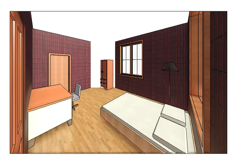
5. Place the Furniture components for the Bedroom in the desired locations as shown in the figure below
Step 5: (Restroom and Toilets)
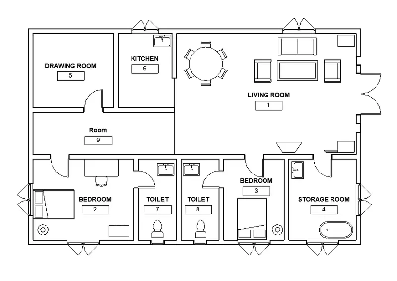
1. Now, we need to insert the Plumbing components in the Restrooms and Toilets
2. Go to the Architectural tab and select the Load Component option
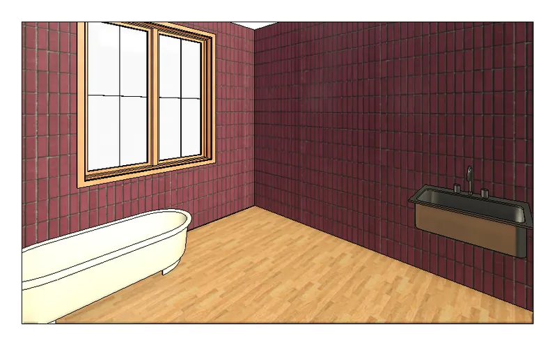
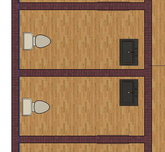
3. In that tab, select load family (Libraries > US > Plumbing) and select the required components such as bathtub, toilet sink, and other plumbing fixtures
4. After loading the components, Go to the Architectural tab and select the load components option
5. Place the Plumbing components for the Restroom and Toilets in the desired locations as shown in the figure below
Step 6: (Kitchen)
1. Now, we need to insert the Domestic components in the Kitchen room
2. Go to the Architectural tab and select the Load Component option
3. In that tab, select load family (Libraries > US > Special Equipment > Domestic) and select the required components such as Countertops, Gas stove, Coffee maker, Cabinets, and Sink
4. After loading the components, Go to the Architectural tab and select the load components option
5. Place the Domestic components for the Kitchen room in the desired locations as shown in the figure below
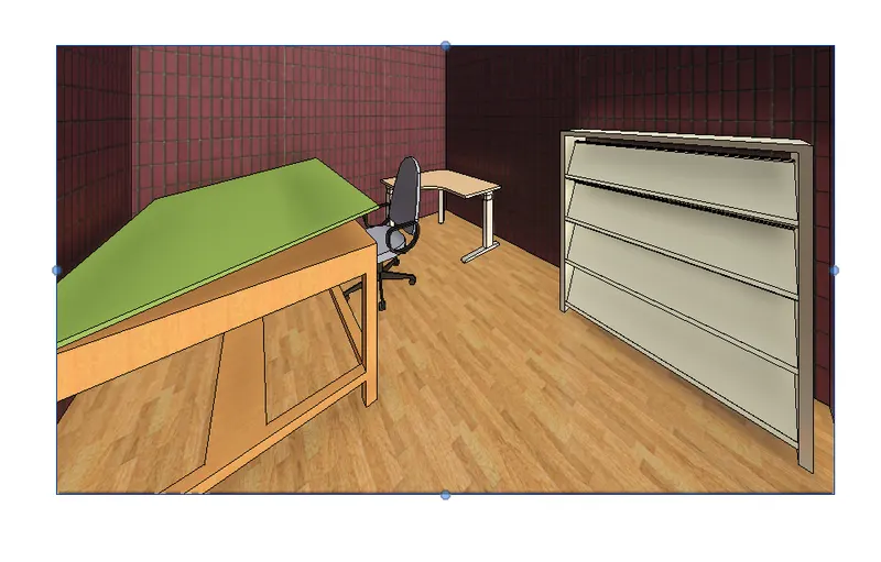
6. Additionally, we placed Furniture components in the drawing-room as shown in the figure below
RESULT:
All the components are inserted successfully in the desired locations for the different rooms.
1. Living Room:
2. Dining Room:
3. Bed Room:
4. Rest Rooms:
5. Drawing Room:
Top View:
Front-Side View: