Creating Bar Bending schedule, Different Door types, and Creation of standard drawing templates using AutoCad
Creating Bar Bending schedule, Different Door types, and Creation of standard drawing templates using AutoCad
1. Creating the Templates:
AIM:
To Create the Custom1_titleblock and Custom2_titleblock templates using Autocad
INTRODUCTION:
In this project, we have to create the templates of custom1_titleblock and Custom2_titleblock using various tools like MText, Block, and Attributes. The template is arranged in the table format that specifies the drawing and which was provided in the corner of the drawing sheet
COMMANDS USED:
1. Units
2. Limits
3. Line
4. Rectangle
5. Offset
6. Trim
7. Move
8. MText
9. Block definition
10. Block insert
11. Attribute
PROCEDURE:
1. Open the Autocad application and Type Qnew to open New drawing
2. In the startup dialog box set Metric as the default settings
3. Type UN and set the units as Decimal and precision as 0.0
4. Set the units as Millimetres in the insertion scale
5. Type Limits in the command box and set the lower limit as 0,0 and upper limit as 10000,10000
6. Type Z enter for Zoom and A for Zoom all
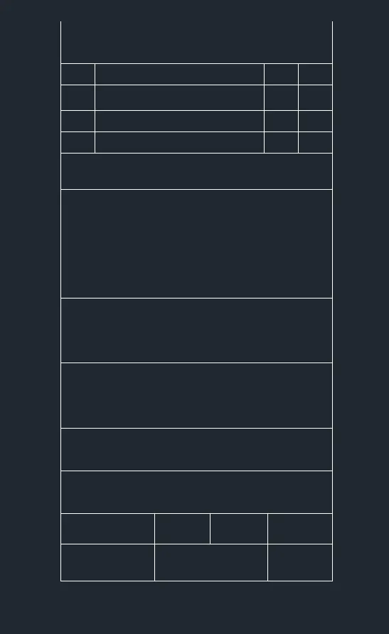
Step 1: (Custom1_titleblock)
1. Select the Rectangle tool by typing REC or Rectangle in the command box
2. Draw a rectangle of size @2400,5200 and explode it by using Explode Command
3. Select the Offset tool by typing O or Offset in the command box
4. Give Offset distance as 500 and Offset the top of the line through inside
5. Give offset distance again as 200 and offset the top of the line through inside for four times as shown in the figure below
6. Repeat the Offset command and give Offset distance as 300, 1000, 600, 600, 400, 400, 300, 300 respectively
7. Select the Trim tool by typing TR or Trim in the command box
8. Trim the unnecessary lines as shown in the figure below
9. Select the Offset tool by typing O or Offset in the command box
10. Give Offset distance as 300, 1500, 300, 300 respectively
11. Select the left line and offset it through inside as shown in the figure below
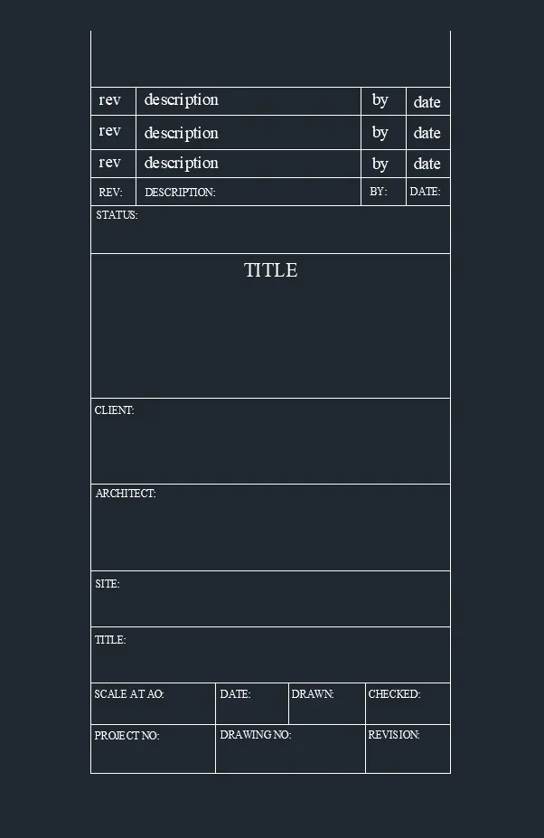
Step 2:
1. Go to Annotate tab and Open the Text Style dialog box
2. Give Text Style as Standard, Font style as Times New Roman, and Text height as 500
3. Select Multiline Text and type the text as rev, description, by, and date.
4. Select the Copy tool by typing CO or COPY in the command box
5. Select the MText and Paste it through the desired locations
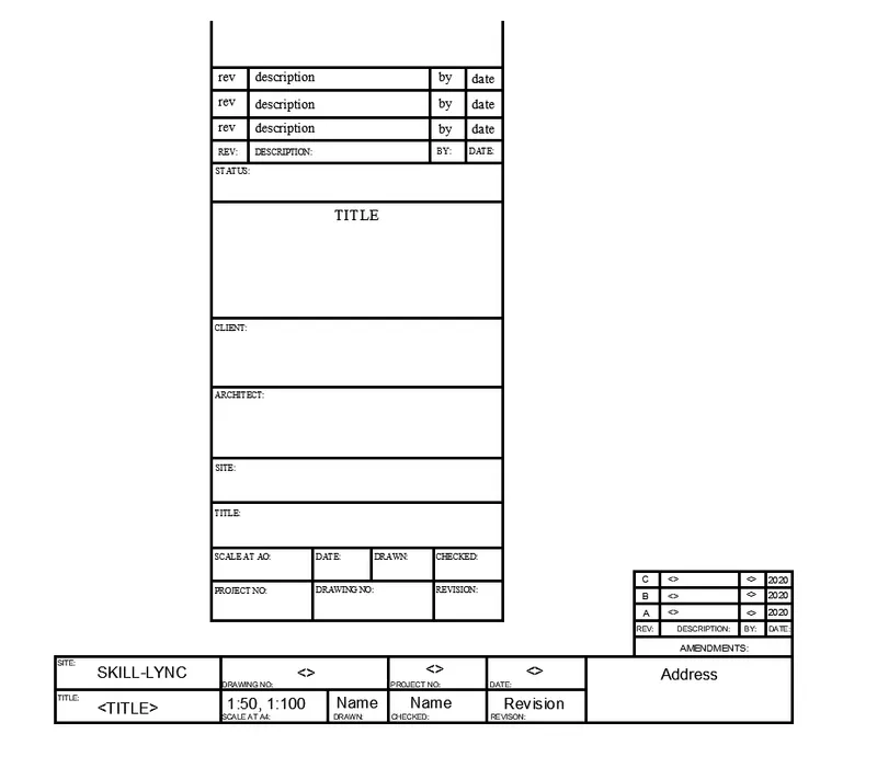
6. Select Multiline Text again and type the text as Status, Title, Client, Architect, Site, Scale at AO, Project No., Date, Drawing No., Drawn, Checked, Revision respectively
7. Place the Text in the desired locations as shown in the figure below
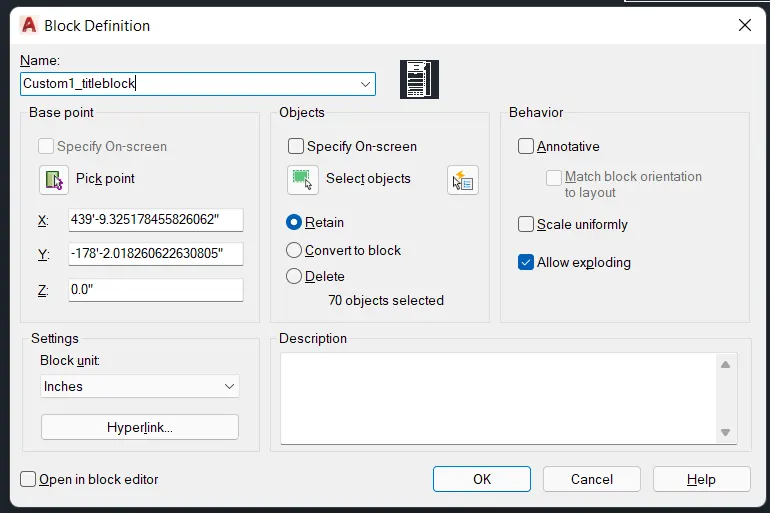
Step 3:
1. Open the Block Definition dialog box by typing B or Block in the command box
2. Give the Name of the block as Custom1_titleblock
3. Select pick point in the block definition and pick a point in the Sketched Template
4. Select the Object as Whole table template and press Enter
5. Click Allow Exploding, Select Retain option, and Press OK to convert into the block as shown in the figure below
6. Open the Insert block by typing I or Insert in the command box
7. Insert the Custom1_titleblock into the screen
Step 4: (Custom2_titleblock)
1. Select the Rectangle tool by typing REC or Rectangle in the command box
2. Draw a rectangle of size @1000,12000 and explode it by using Explode Command
3. Select the Offset tool by typing O or Offset in the command box
4. Give Offset distance as 500 and Offset the top of the line through inside
5. Repeat the Offset command and give Offset distance as 2500, 2532, 1500, 1500, 3000 respectively
6. Select the left line and Offset it through inside as shown in the figure below
7. Select the Trim tool by typing TR or Trim in the command box
8. Trim the unnecessary lines as shown in the figure below

Step 5:
1. Go to Annotate tab and Open the Text Style dialog box
2. Give Text Style as Standard, Font style as Times New Roman, and Text height as 500
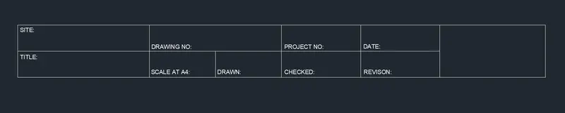
3. Select Multiline Text and type the text as Site, Title, Dawing No., Scale at A4, Drawn, Project No., Checked, Date and Revision respectively
4. Select the Move tool by typing M or Move in the command box
5. Select the Text and Move it through the desired locations as shown in the figure below
Step 6:
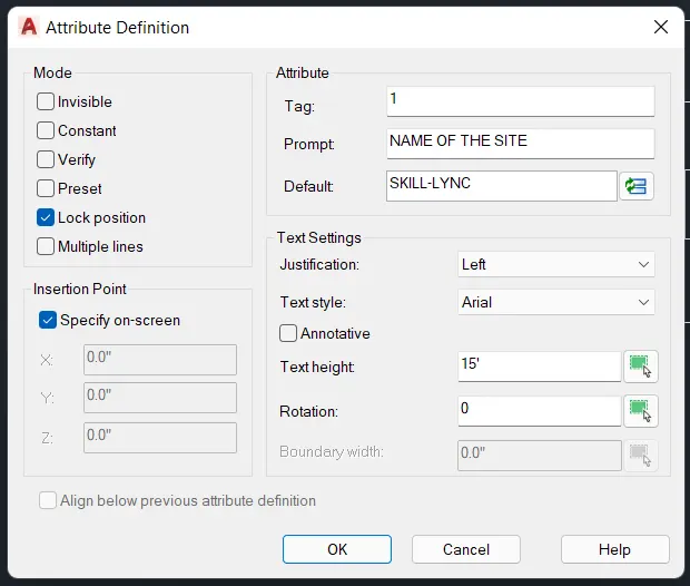
1. Open Attribute Definition by typing ATT or Attributes in the command box
2. Give the Tag as 1 (i.e., it will be visible before we convert it into the block)
3. Give the Promot as the Name of the Site
4. Give the Default as Site (i.e., it will be visible after we convert into the block)
5. Select the Lock Position option and Insertion point as specified on the screen
6. Specify the location where we want to insert the attribute text
Step 7:
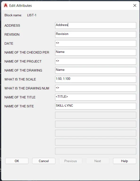
1. Similarly do the same process for all the attributes
Step 8:
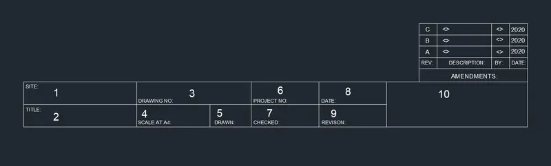
1. Draw the table below the previous table as shown in the figure below
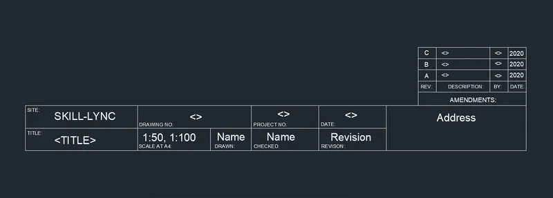
2. Select Multiline Text and type the text as Rev, Description, By, Date, A, B, C, <> and 2020 respectively
3. Select the Move tool by typing M or Move in the command box
4. Select the MText and Move it through the desired locations as shown in the figure below
5. Select the Copy tool by typing CO or COPY in the command box
6. Select the Text and Paste it through the desired locations
Step 9:
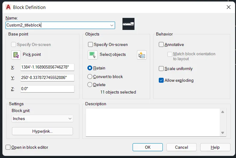
1. Open the Block Definition dialog box by typing B or Block in the command box
2. Give the Name of the block as Custom2_titleblock
3. Select pick point in the block definition and pick a point in the Sketched Template
4. Select the Object as Whole table template and press Enter
5. Click Allow Exploding, Select Retain option, and Press OK to convert into the block as shown in the figure below
6. Open InsertBlock by typing I or Insert in the command box
7. Insert the Custom2_titleblock into the screen
RESULT:
2. Creating Door Panels for Warehouse
AIM:
To create the door types D1 and D2 for the warehouse using Autocad
INTRODUCTION:
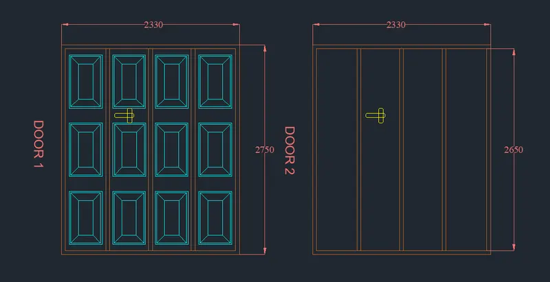
In this project, we create two sides of the door type for the warehouse, and has been drafted with the name of Door 1 and Door 2 using various tools in the Autocad.
The first drawing D1 Shows the front view of the door and the second drawing D1 Shows the back view of the door
COMMANDS USED:
1. Units
2. Limits
3. Rectangle
4. Offset
5. Divide
6. Line
7. Mirror
8. Copy
9. Block definition
10. Block insert
11. Dim Linear
12. MText
PROCEDURE:
1. Open the Autocad application and Type Qnew to open New drawing
2. In the startup dialog box set Metric as the default settings
3. Type UN and set the units as Decimal and precision as 0.0
4. Set the units as Millimetres in the insertion scale
5. Type Limits in the command box and set the lower limit as 0,0 and upper limit as 10000,10000
6. Type Z enter for Zoom and A for Zoom all
Step 1: (DOOR 1)
1. Select the Rectangle tool by typing REC or Rectangle in the command box
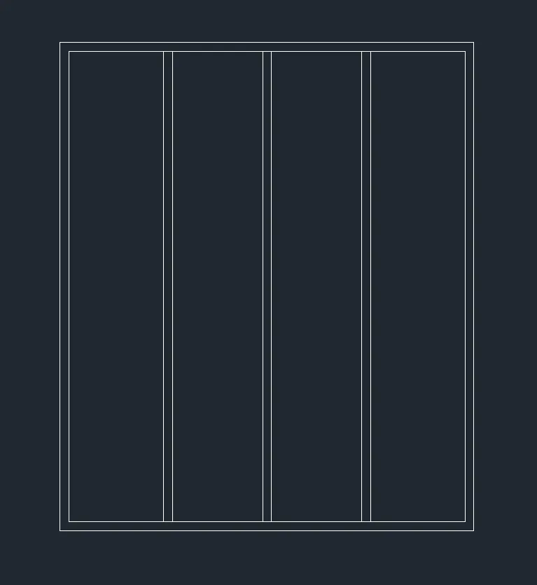
2. Draw a rectangle with the size of 2330x2750mm
3. Select the Offset tool by typing O or Offset in the command box
4. Give offset distance as 50mm and offset it through the inside as shown in the figure below
5. Select the Divide tool by Typing DIV or Divide in the command box
6. Divide the top line into Four segments and draw vertical lines from it
7. Select the Offset tool and give the Offset distance as 25mm
8. Offset the divided lines on both sides for thickness and delete the centerline
Step 2:
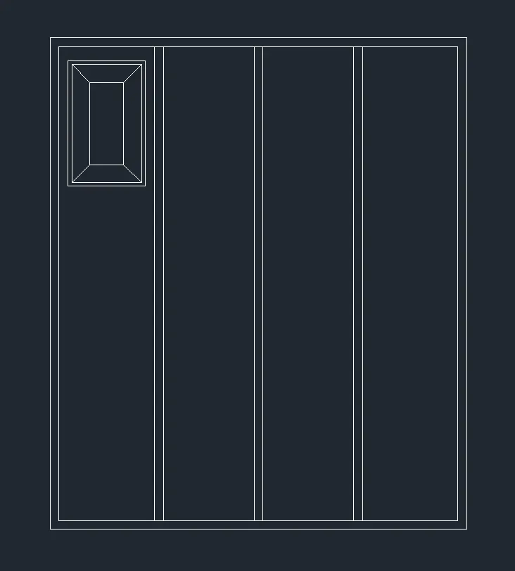
1. Select the Rectangle tool by typing REC or Rectangle in the command box
2. Create a rectangle to show the panel and insert it in the door as shown in the figure below
3. Select the Offset tool and give offset distance as 25mm and 100mm respectively
4. Offset it through inside as shown in the figure below
5. Draw a line joining the corners of the rectangles as shown in the figure below
Step 3:
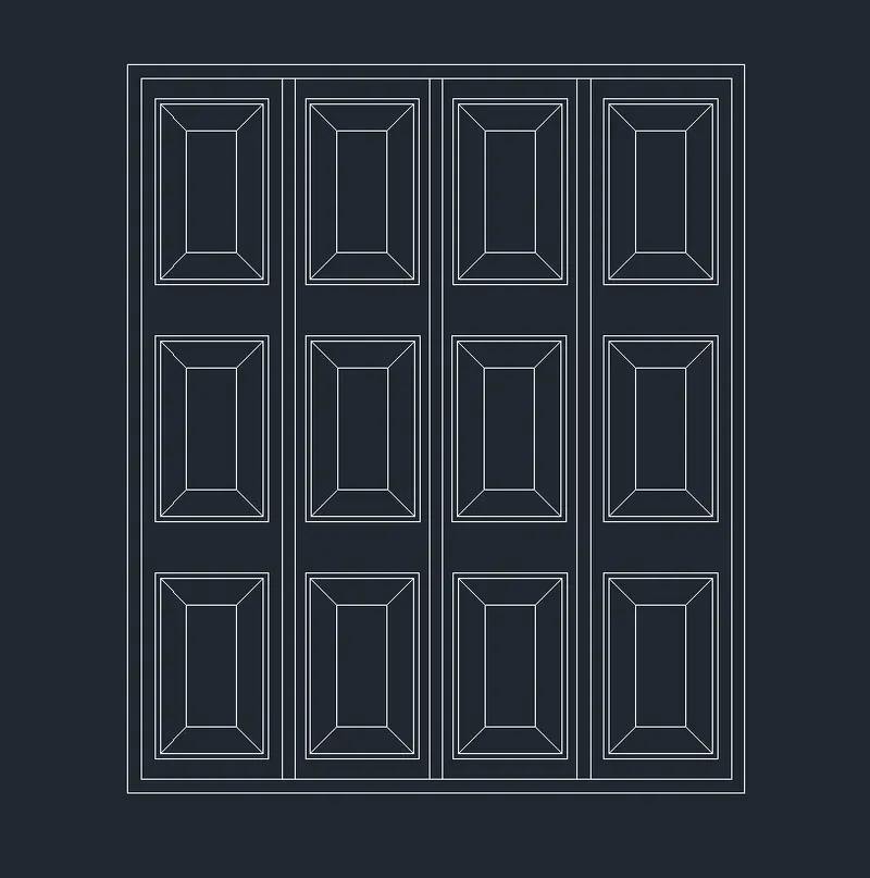
1. Select the Mirror tool by Typing MIR Mirror in the command box
2. Select the panel and mirror it through the both sides
3. Select the Copy tool by typing CO or COPY in the command box
4. Select the panel and copy it through the desired locations as shown in the figure below
Step 4:
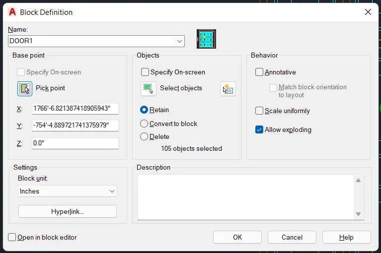
1. Open the Block Definition dialog box by typing B or Block in the command box
2. Give the Name of the block as DOOR 1
3. Select pick point in the block definition and pick a point in the Door
4. Select the Object as Whole Door and press Enter
5. Click Allow Exploding, Select Retain option, and Press OK to convert into the block as shown in the figure below
6. Open the Insert block by typing I or Insert in the command box
7. Insert the Door 1 into the screen
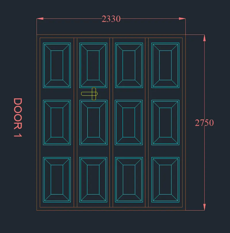
8. Select the Dimension tool by typing DIMLIN in the command box
9. Specify the dimensions of the door as per the drawing
10. Select Multiline Text and type the text as DOOR 1 and place it as shown in the figure below
Step 5: (DOOR 2)
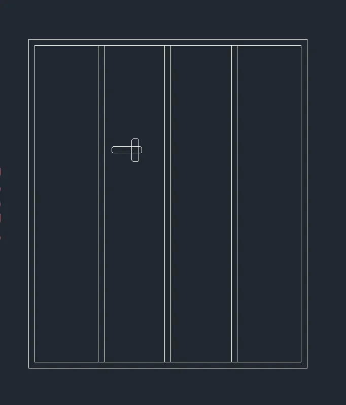
1. Select the Rectangle tool by typing REC or Rectangle in the command box
2. Draw a rectangle with the size of 2330x2750mm
3. Select the Offset tool by typing O or Offset in the command box
4. Give offset distance as 50mm and offset it through the inside as shown in the figure below
5. Select the Divide tool by Typing DIV or Divide in the command box
6. Divide the top line into Four segments and draw vertical lines from it
7. Select the Offset tool and give the Offset distance as 25mm
8. Offset the divided lines on both sides for thickness and delete the centerline
Step 6:
1. Select the Rectangle tool and draw two rectangles perpendicular to each other
2. Place it on the door to show the lock position
Step 7:
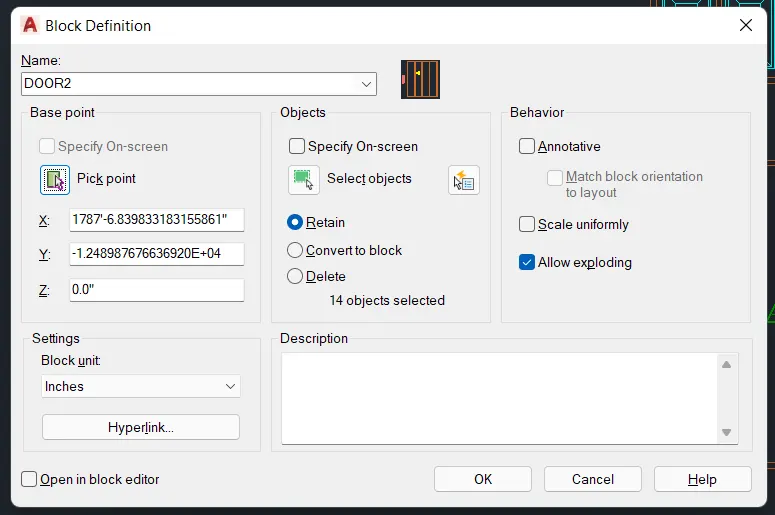
1. Open the Block Definition dialog box by typing B or Block in the command box
2. Give the Name of the block as DOOR 2
3. Select pick point in the block definition and pick a point in the Door
4. Select the Object as Whole Door and press Enter
5. Click Allow Exploding, Select Retain option, and Press OK to convert into the block as shown in the figure below
Step 8:
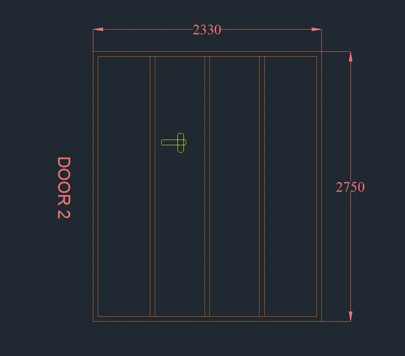
1. Select the Dimension tool by typing DIMLIN in the command box
2. Specify the dimensions of the door as per the drawing
3. Select Multiline Text and type text as DOOR 2 and place it as shown in the figure below
RESULT:
3. Creating Electrical Symbols
AIM:
To create Electrical Symbols as a Block and Insert them into a Table using Autocad
INTRODUCTION:
In this project, we create different types of electrical symbols and the legend has been created with the blocks of the symbols along with the table insertion.
The Symbols are denoting the electrical items such as symbols and sockets
COMMANDS USED:
1. Circle
2. Line
3. Rectangle
4. Hatch
5. Mirror
6. Copy
7. Mtext
8. Block definition
9. Block insert
10. Field
PROCEDURE
1. Open the Autocad application and Type Qnew to open New drawing
2. In the startup dialog box set Metric as the default settings
3. Type UN and set the units as Decimal and precision as 0.0
4. Set the units as Millimetres in the insertion scale
5. Type Limits in the command box and set the lower limit as 0,0 and upper limit as 10000,10000
6. Type Z enter for Zoom and A for Zoom all
Step 1: (Single gang switch)
1. Select the Circle tool by typing C or Circle in the command box
2. Draw a circle of radius 100mm
3. Select the Line tool by typing L or Line in the command box
4. Draw a vertical line inclined through the circle and draw a horizontal line perpendicular to the previous line as shown in the figure below

Step 2: (Double gang switch)
1. Select the Circle tool by typing C or Circle in the command box
2. Draw a circle of radius 100mm
3. Select the Line tool by typing L or Line in the command box
4. Draw a vertical line inclined through the circle and draw two horizontal lines perpendicular to the previous line as shown in the figure below

Step 3: (Triple gang switch)
1. Select the Circle tool by typing C or Circle in the command box
2. Draw a circle of radius 100mm
3. Select the Line tool by typing L or Line in the command box
4. Draw a vertical line inclined through the circle and draw three horizontal lines perpendicular to the previous line as shown in the figure below

Step 4: (Single two-way switch)
1. Select the Circle tool by typing C or Circle in the command box
2. Draw a circle of radius 100mm
3. Select the Line tool by typing L or Line in the command box
4. Draw a vertical line inclined through the circle and draw a horizontal line perpendicular to the previous line as shown in the figure below
5. Select Hatch Pattern as solid and pick the point as a circle to fill the hatch

Step 5: (Double two-way switch)
1. Select the Circle tool by typing C or Circle in the command box
2. Draw a circle of radius 100mm
3. Select the Line tool by typing L or Line in the command box
4. Draw a vertical line inclined through the circle and draw two horizontal lines perpendicular to the previous line as shown in the figure below
5. Select Hatch Pattern as Solid and pick the point as a circle to fill the hatch

Step 6: (Triple two-way switch)
1. Select the Circle tool by typing C or Circle in the command box
2. Draw a circle of radius 100mm
3. Select the Line tool by typing L or Line in the command box
4. Draw a vertical line inclined through the circle and draw three horizontal lines perpendicular to the previous line as shown in the figure below
5. Select Hatch Pattern as Solid and pick the point as a circle to fill the hatch

Step 7: (Switch cross)
1. Select the Circle tool by typing C or Circle in the command box
2. Draw a circle of radius 100mm
3. Select the Line tool by typing L or Line in the command box
4. Draw a vertical line inclined through the circle and draw a horizontal line perpendicular to the previous line as shown in the figure below
5. Select Hatch Pattern as Solid and pick the point as a circle to fill the hatch
6. Select the Mirror tool and Mirror it through the top and bottom as shown in the figure

Step 8: (Switch serial)
1. Select the Circle tool by typing C or Circle in the command box
2. Draw a circle of radius 100mm
3. Select the Line tool by typing L or Line in the command box
4. Draw a vertical line inclined through the circle and draw a horizontal line perpendicular to the previous line as shown in the figure below
5. Select the Mirror tool and Mirror it through the left side as shown in the figure

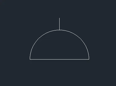
Step 9: (Single socket)
1. Select the Circle tool by typing C or Circle in the command box
2. Draw a circle of radius 100mm and divide it into the half
3. Draw a line of 10mm at the top as shown in the figure below
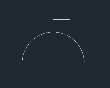
Step 10: (Single socket for lamp)
1. Select the Circle tool by typing C or Circle in the command box
2. Draw a circle of radius 100mm and divide it into the half
3. Draw a line of 10mm at the top and draw another line perpendicular to the previous line as shown in the figure below
Step 11: (Double socket)
1. Select the Circle tool by typing C or Circle in the command box
2. Draw a circle of radius 100mm and Divide it into the half
3. Draw a Line of 10mm at the top as shown in the figure below
4. Select the Copy tool and copy it to create the same and place it using snap-on

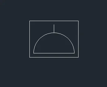
Step 12: (Floor socket single)
1. Select the Circle tool by typing C or Circle in the command box
2. Draw a circle of radius 100mm and Divide it into the half
3. Draw a line of 10mm at the top as shown in the figure below
4. Draw a rectangle surrounding the single socket
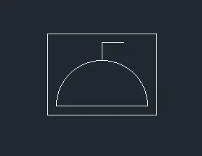
Step 13: (Floor socket single for lamp)
1. Select the Circle tool by typing C or Circle in the command box
2. Draw a circle of radius 100mm and Divide it into the half
3. Draw a Line of 10mm at the top and draw another line perpendicular to the previous line as shown in the figure below
4. Draw a rectangle surrounding the single socket
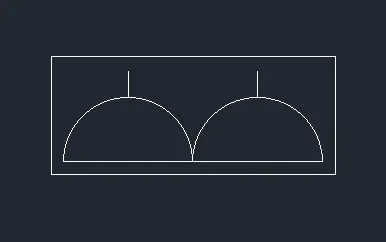
Step 14: (Floor socket double)
1. Select the Circle tool by typing C or Circle in the command box
2. Draw a circle of radius 100mm and Divide it into the half
3. Draw a Line of 10mm at the top as shown in the figure below
4. Select the Copy tool and copy it to create the same and place it using snap-on
5. Draw a rectangle surrounding the double socket
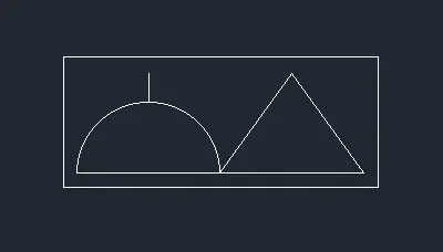
Step 15: (Floor socket single telephone)
1. Select the Circle tool by typing C or Circle in the command box
2. Draw a circle of radius 100mm and divide it into the half
3. Draw a Line of 10mm at the top as shown in the figure below
4. Create a Triangle beside the Single socket as shown in the figure below
5. Draw a rectangle surrounding to it
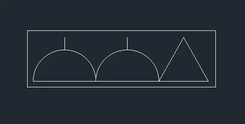
Step 16: (Floor socket double telephone)
1. Select the Circle tool by typing C or Circle in the command box
2. Draw a circle of radius 100mm and divide it into the half
3. Draw a line of 10mm at the top as shown in the figure below
4. Select the Copy tool and copy it to create the same and place it using snap-on
5. Create the Triangle beside the double socket as shown in the figure below
6. Draw a rectangle surrounding to it
Step 17: (Telephone Socket)
1. Select the Line tool by typing L or Line in the command box
2. Draw a Triangle by using the Line tool

Step 18: (Internet socket)
1. Draw a Triangle by using the Line tool
2. Insert the text as "i" in the triangle

Step 19: (TV socket)
1. Draw a Triangle by using the Line tool
2. Insert the text as "TV" in the triangle

Step 20: ( Weatherproof socket)
1. Draw a Triangle by using the Line tool
2. Insert the text as "W" in the triangle

Step 21: (Duct base section)
1. Draw a Rectangle by using REC Command
2. Draw a single line below the rectangle as shown in the figure below
3. Similarly, Draw two lines above the rectangle
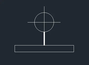
Step 22: (Wall Bracket)
1. Draw a Rectangle by using REC Command
2. Draw a Circle above the rectangle by using Circle Command
3. Draw the lines connecting both Circle and Rectangle
Step 23: (Picture Lamp)
1. Draw a Rectangle by using REC Command
2. Draw another small rectangle and place it below the previous rectangle
3. Draw two lines connecting both rectangles
Step 24:
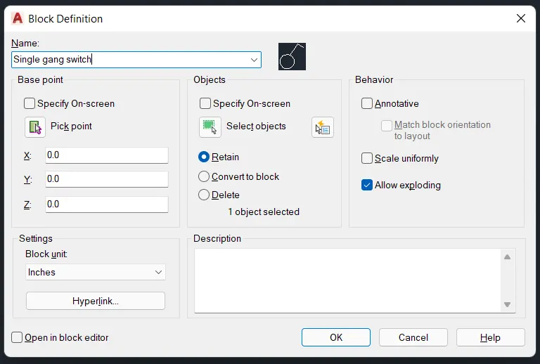
1. Open the Block Definition dialog box by typing B or Block in the command box
2. Give the Name of the block as a Single gang switch
3. Select pick point in the block definition and pick a point in the Symbol
4. Select the Object as Symbol and press enter
5. Click Allow Exploding, Select Retain option, and Press OK to convert into the block as shown in the figure below
Step 25:
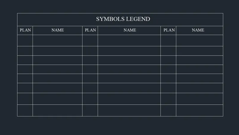
1. Select the Rectangle tool by typing REC or Rectangle in the command box
2. Draw a rectangle to create the table of contents
3. Select the Offset command and do the offsets as per the requirement
4. Go to Annotate tab and Open the Text Style dialog box
5. Give Text Style as Standard, Font style as Times New Roman, and Text height as 500
6. Select Multiline Text and type the text as Symbols legend, Plan, and Name respectively
7. Select the Copy tool by typing Co or COPY in the command box
8. Select the Text and copy it through the desired locations as shown in the figure below
Step 26:
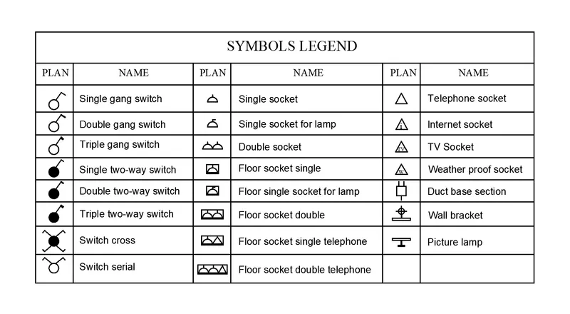
1. Open the Insert block by typing I or Insert in the command box
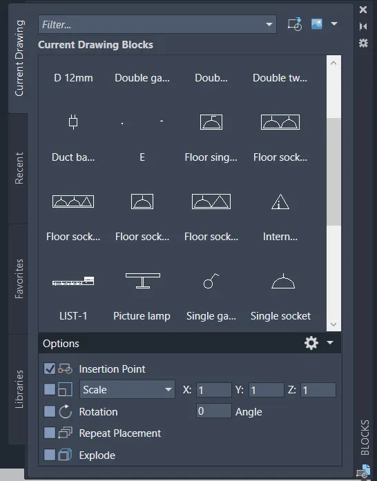
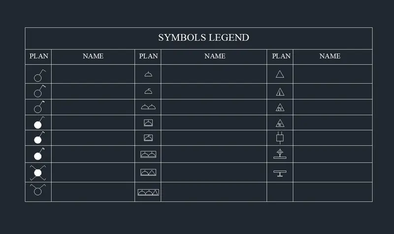
2. Insert all the symbols into the table at the desired positions
Step 27:
1. Open the FieldDialog box by typing Field in the command box
2. Select FieldCategory as objects and Field name as Named object
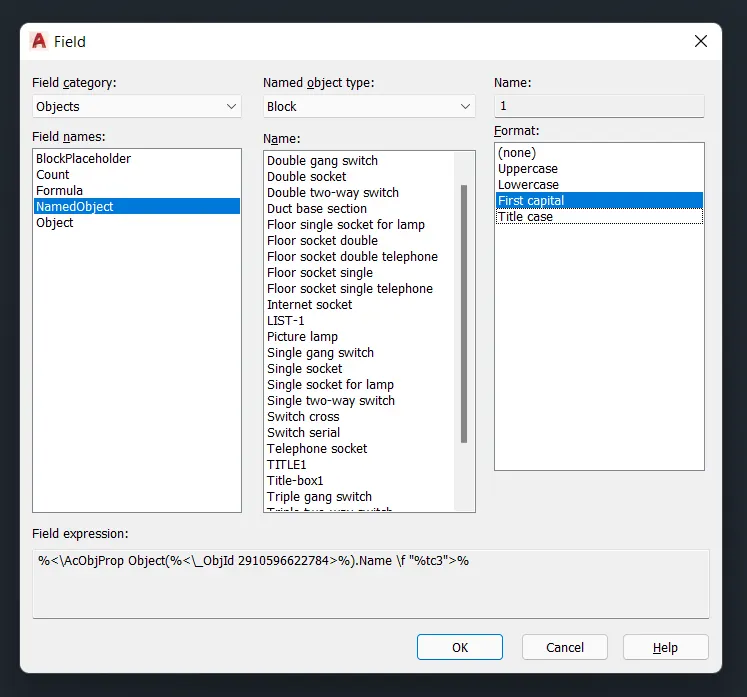
3. Select the name of the object that you want to insert and select the format of the text as First capital (E.g.: For single gang switch - Select from the field - select format as upper case)
4. Insert it at the desired location. Similarly, do the same process for all the symbol names
RESULT:
4. Creating Door types for Residential buildings:
AIM:
To draw the door types for a residential building as a Block.
INTRODUCTION:
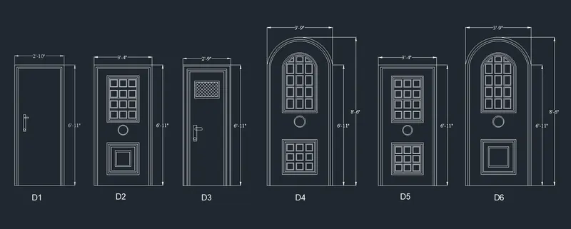
The door types for the residential building are drawn with the various types of the front elevation designs with the names D1, D2, D3, D4, D5, and D6
COMMANDS USED:
1. Units
2. Limits
3. Rectangle
4. Circle
5. Offset
6. Trim
7. Block definition
8. Mtext
PROCEDURE:
1. Open the Autocad application and Type Qnew to open New drawing
2. In the startup dialog box set Feet Inches as the default settings
3. Type UN and set the units as Architectural and precision as 0.0
4. Set the units as Inches in the insertion scale
5. Type Limits in the command box and set the lower limit as 0,0 and upper limit as 100',100'
6. Type Z enter for Zoom and A for Zoom all
Step 1: (D1)
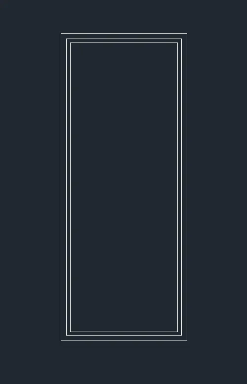
1. Select the Rectangle command by typing REC or Rectangle in the command box
2. Draw a rectangle with dimensions 2'10" as length and 6'11" as width
3. Select the Offset tool by typing O or Offset in the command box
4. Give offset distance as 1.5" and 1" and offset it through inside as shown in the figure below
Step 2:
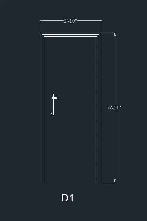
1. Select the Rectangle tool by typing REC or Rectangle in the command box
2. Draw two rectangles perpendicular to each other and fillet the corners with a radius of 0.2"
3. Draw a circle with a radius of 0.1" in the rectangle
4. Give dimensions as per drawing using the DimLinear command
5. Select Multiline Text and type the text as D1
6. Create it as a Block and give the block name as Door 1
Step 3 (D2)
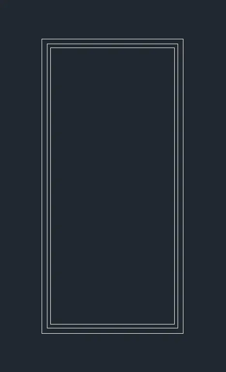
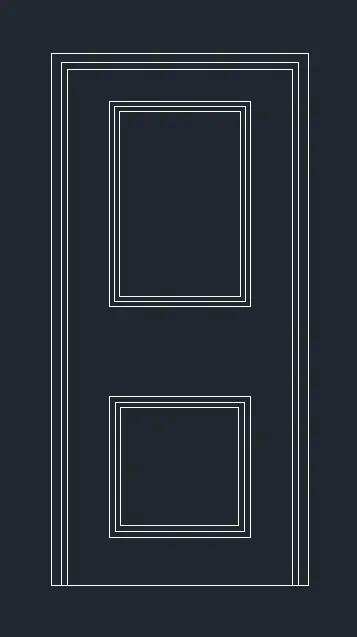
1. Select the Rectangle command by typing REC or Rectangle in the command box
2. Draw a rectangle with dimensions 3'4" as length and 6'11" as width
3. Select the Offset tool by typing O or Offset in the command box
4. Give offset distance as 1.5" and 1" and offset it through inside as shown in the figure below
Step 4:
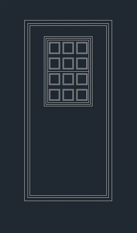
1. Select the Rectangle tool by typing REC or Rectangle in the command box
2. Draw a rectangle for the panel with the dimension 2' as length and 3' as width
3. Select the Offset tool by typing O or offset in the command box
4. Give offset distance as 1" and offset it through inside two times

Step 5:
1. Select the Rectangle tool by typing REC or Rectangle in the command box
2. Draw a rectangle for the panel with the dimension 6" as length and 10" as width
3. Select the Offset tool by typing O or offset in the command box
4. Give offset distance as 1" and offset it inside
5. Select the Copy tool and copy it to desired locations as shown in the figure below
Step 6:
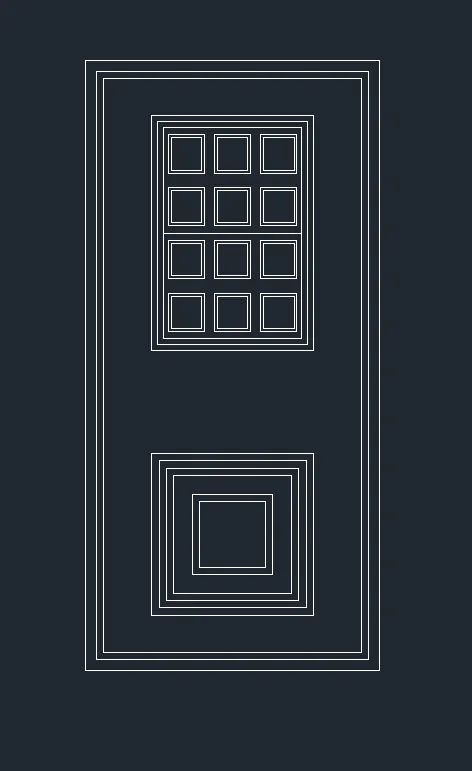
1. Select the Rectangle tool by typing REC or Rectangle in the command box
2. Draw a rectangle for the panel with the dimension 2' as length and 2' as width
3. Select the Offset tool by typing O or Offset in the command box
4. Give offset distance as 1" and offset it through inside three times
5. Select the Offset tool again and give the offset distance as 4" and 5" respectively
6. Offset it through inside from the previous line as shown in the figure below
Step 7:
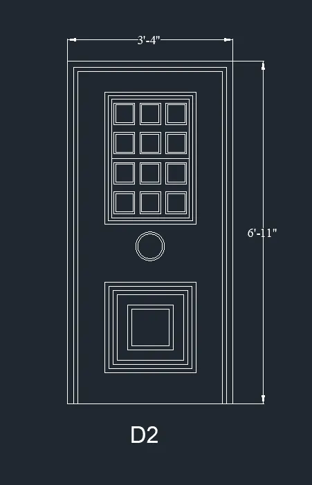
1. Select the Circle tool by typing C or Circle in the command box
2. Draw a circle with a radius of 10" and place it on the middle section of the door
3. Select the Offset tool and give offset distance as 1"
4. Offset it through inside as shown in the figure below
5. Give dimensions as per drawing using the DimLinear command
6. Select Multiline Text and type text as D2
7. Create it as a Block and give the block name as Door 2
Step 8: (Door 3)
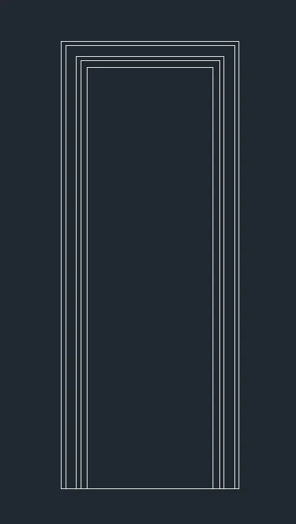
1. Select the Rectangle command by typing REC or Rectangle in the command box
2. Draw a rectangle with dimensions 2'9" as length and 6'11" as width
3. Select the Offset tool by typing O or Offset in the command box
4. Give offset distance as 1", 1.5", 1," 1" and offset it through inside as shown in the figure below
Step 9:
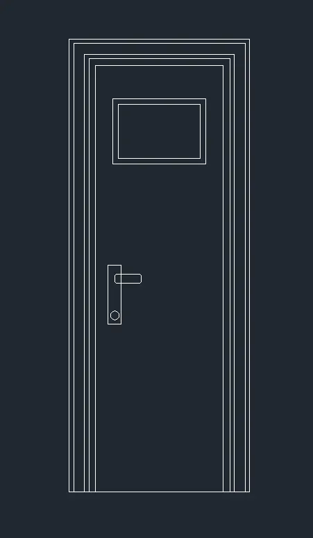
1. Select the Rectangle tool and draw a rectangle at the top for ventilation 1'6" x 10"
2. Select the Offset command and give offset distance as 1" for thickness
3. Draw two rectangles perpendicular to each other for the lock as shown in the figure below
4. Select the Circle tool and draw a circle inside the lock
Step 10:
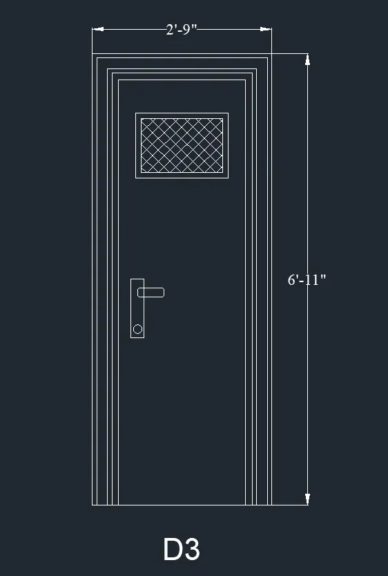
1. Select the Hatch tool and do the hatching inside the ventilation
2. Give dimensions as per drawing using the DimLinear command
3. Select Multiline Text and type text as D3
4. Create it to block and give block name as Door 3
Step 11: (Door 4)
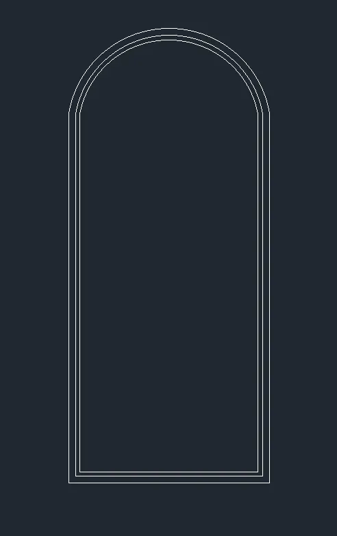
1. Select the Rectangle tool and draw a rectangle of dimension 3'9" x 6'11"
2. Select the Arc tool and draw an arc connecting both endpoints
3. Select the Offset command and give offset distances 1.5" and 1" respectively
4. Offset the arc line through inside two times as shown in the figure below
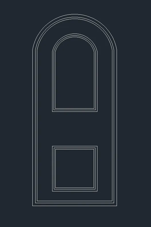
Step 12:
1. Select the Offset tool and give the offset distance as 8"
2. Offset the previous Arc line through inside as shown in the figure below
3. Select the Offset tool again and give offset distance as 1"
4. Select the preview arc line and offset it through inside two times to show the thickness
5. Similarly draw another rectangle of dimension 2' x 2'
6. Select the Offset command and give offset distance as 1"
7. Offset the below rectangle two times to show the thickness
Step 13:
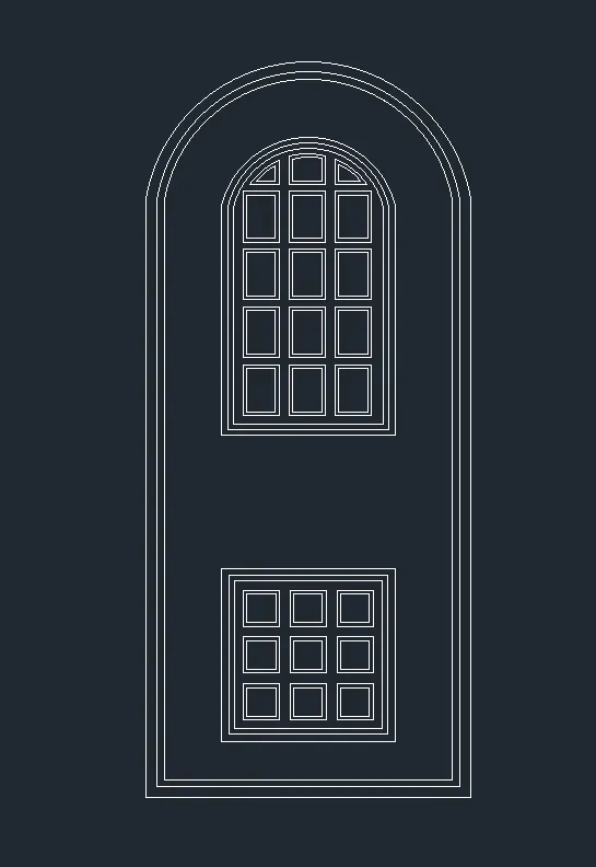
1. Select the Rectangle tool and draw a rectangle of size 8"×8" for the panel
2. Select the Offset tool and give the offset distance as 0.8"
3. Offset the rectangle inside
4. Select the Copy tool and Copy the panels to the desired location as shown in the figure below
5. Similarly do the same process for another panel below the door
Step 14:
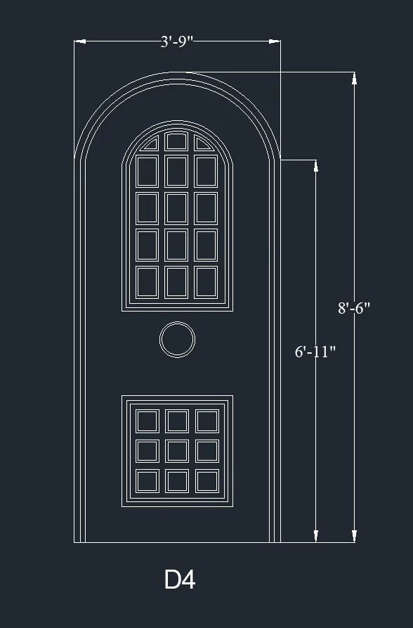
1. Select the Circle tool by typing C or Circle in the command box
2. Draw a circle to show the lock inside the door panel
3. Give dimensions as per drawing using the DimLinear command
4. Select Multiline Text and type text as D4
5. Create it as a Block and give the block name as Door 4
Step 15: (Door 5)
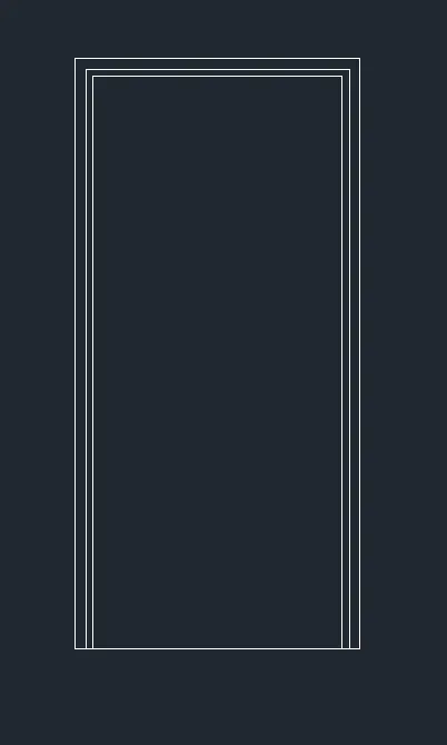
1. Select the Rectangle command by typing REC or Rectangle in the command box
2. Draw a rectangle with dimensions 3'4" as length and 6'11" as width
3. Select the Offset tool by typing O or Offset in the command box
4. Give offset distance as 1.5" and 1" and offset it through inside as shown in the figure below
Step 16:
1. Select the Rectangle tool by typing REC or Rectangle in the command box
2. Draw a rectangle for the panel with the dimension 2' as length and 3' as width
3. Select the Offset tool by typing O or Offset in the command box
4. Give offset distance as 1" and offset it through inside two times
5. Select the Rectangle tool by typing REC or Rectangle in the command box
6. Draw a rectangle for the panel with the dimension 2' as length and 2' as width
7. Select the Offset tool by typing O or Offset in the command box
8. Give offset distance as 1" and offset it through inside for two times as shown in the figure below
Step 17:
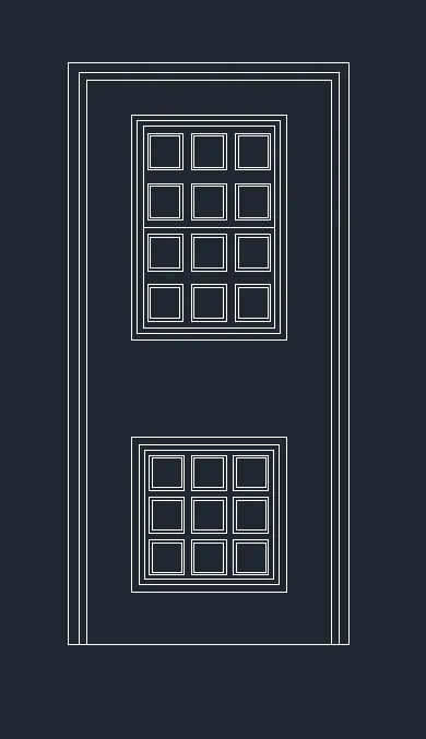
1. Select the Rectangle tool by typing REC or Rectangle in the command box
2. Draw a rectangle for the panel with the dimension 8" as length and 8" as width
3. Select the Offset tool by typing O or Offset in the command box
4. Give offset distance as 0.8" and offset it inside
5. Offset it through inside from the previous line as shown in the figure below
Step 18:
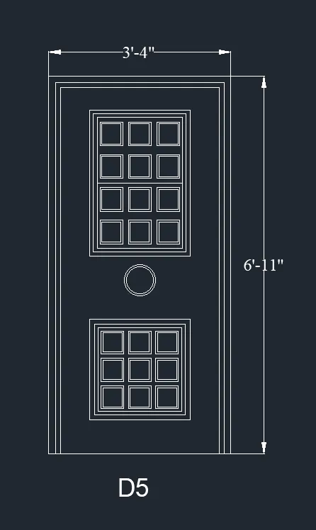
1. Select the Circle tool by typing C or Circle in the command box
2. Draw a circle with a radius of 10" and place it on the middle section of the door
3. Select the Offset tool and give offset distance as 1"
4. Offset it through inside as shown in the figure below
5. Give dimensions as per drawing using the DimLinear command
6. Select Multiline Text and type text as D5
7. Create it as a Block and give the block name as Door 5
Step 19: (Door 6)
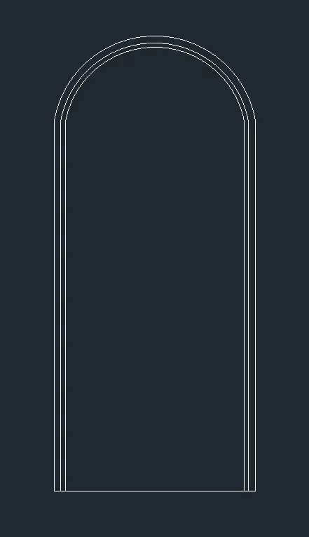
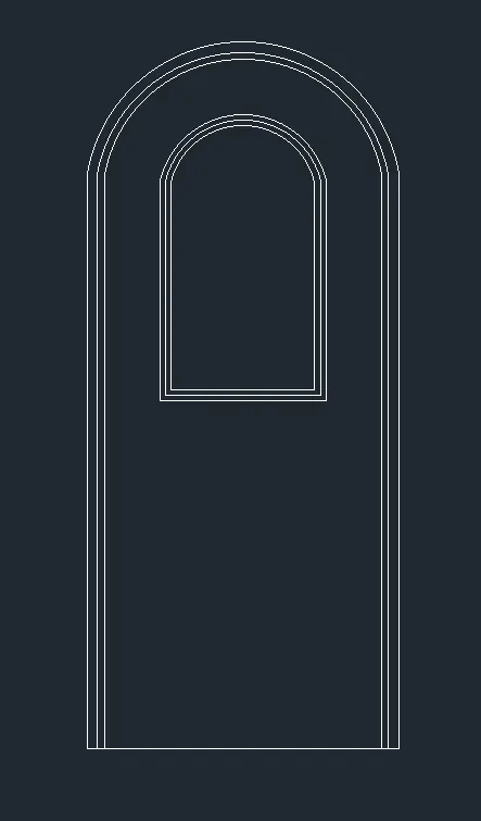
1. Select the Rectangle tool and draw a rectangle of dimension 3'9" x 6'11"
2. Select the Arc tool and draw an arc connecting both endpoints
3. Select the Offset command and give offset distances 1.5" and 1" respectively
4. Offset the arc line through inside two times as shown in the figure below
Step 20:
1. Select the Offset tool and give the offset distance as 8"
2. Offset the previous Arc line through inside as shown in the figure below
3. Select the Offset tool again and give offset distance as 1"
4. Select the preview arc line and offset it through inside two times to show the thickness as shown in the figure below
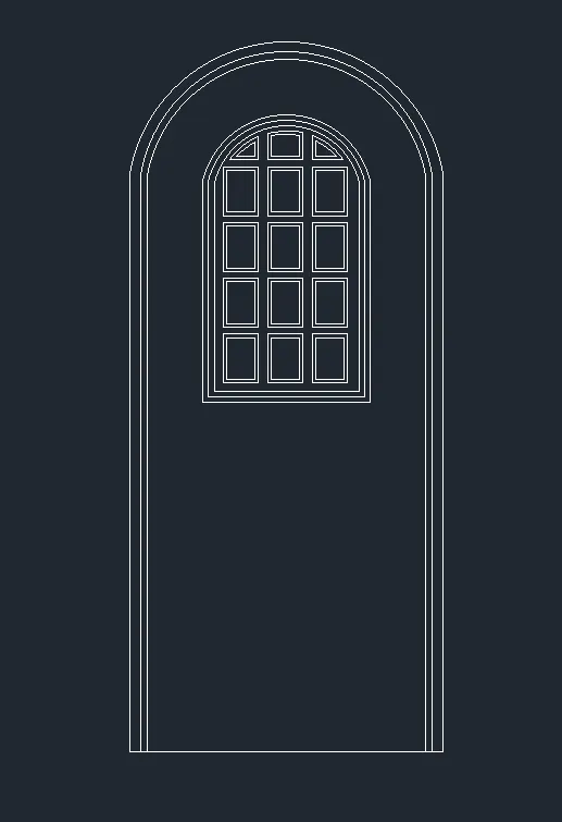
Step 21:
1. Select the Rectangle tool and draw a rectangle of size 8"×8" for the panel
2. Select the Offset tool and give the offset distance as 0.8"
3. Offset the rectangle inside
4. Select the Copy tool and Copy the panels to the desired location as shown in the figure below
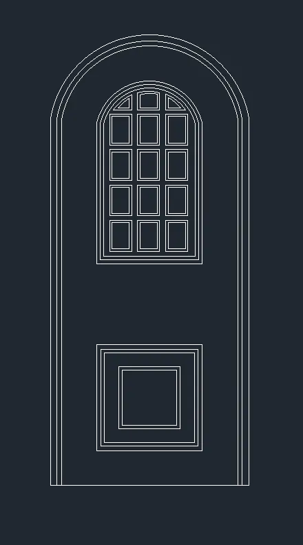
Step 22:
1. Select the Rectangle tool by typing REC or Rectangle in the command box
2. Draw a rectangle of dimension 2' x 2'
3. Select the Offset command and give offset distance as 1"
4. Offset the below rectangle two times to show the thickness
5. Select the Offset tool again and give offset distance as 2.5", 3" respectively
6. Offset the previous line through inside as shown in the figure below
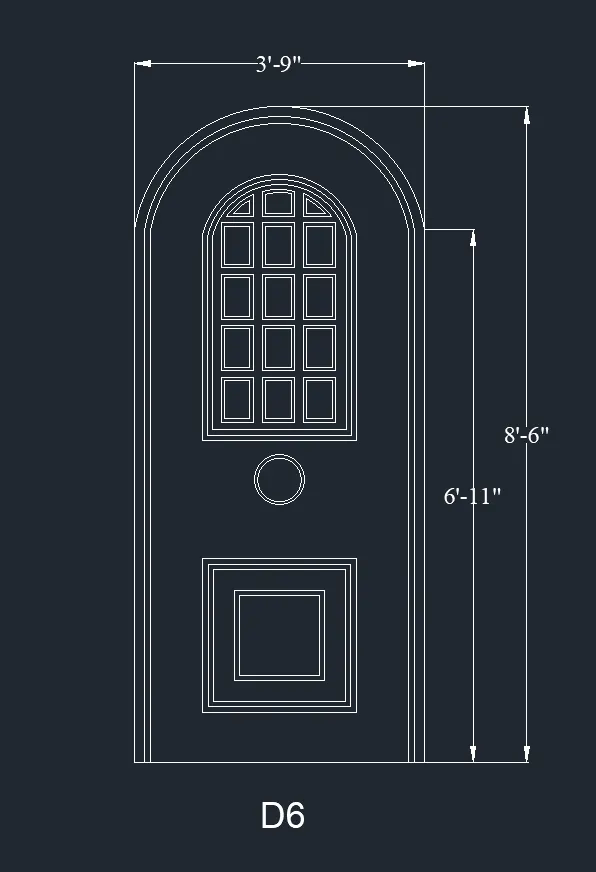
Step 23:
1. Select the Circle tool by typing C or Circle in the command box
2. Draw a circle to show the lock inside the door panel
3. Give dimensions as per drawing using the DimLinear command
4. Select Multiline Text and type text as D6
5. Create it as a Block and give the block name as Door 6
RESULT:
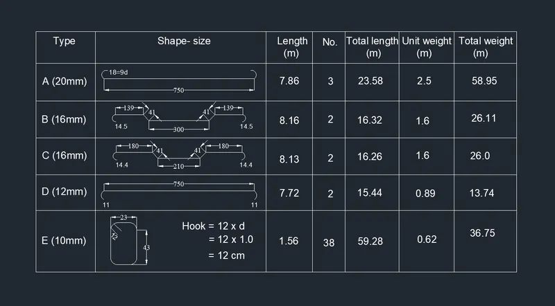
5. Creating Bar Bending Schedule
AIM:
To create a bar bending schedule and insert it as a block
INTRODUCTION:
The shapes of the steel rebar are created and converted into the blocks and attached to the table which was created bar bending schedule with rebar properties
COMMANDS USED:
1. Units
2. Limits
3. Line
4. Arc
5. Rectangle
6. Block definition
7. Insert Block
8. Mtext
PROCEDURE:
1. Open the Autocad application and Type Qnew to open New drawing
2. In the startup dialog box set Metric as the default settings
3. Type UN and set the units as Decimal and precision as 0.0
4. Set the units as Millimetres in the insertion scale
5. Type Limits in the command box and set the lower limit as 0,0 and upper limit as 1000,1000
6. Type Z enter for Zoom and A for Zoom all
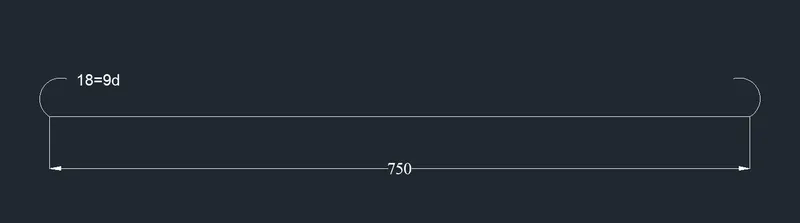
Step 1: (A-20mm)
1. Select the Line Command by typing L or Line in the command box
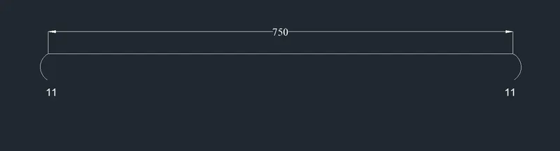
2. Draw a line of length 750mm for a straight bar
3. Select the Arc tool and create an arc to bend upwards at both corners
4. Create it as a Block and give the block name as A-20mm
Step 2: (B-16mm)
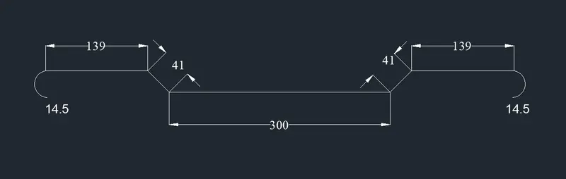
1. Select the Line tool by typing L or Line in the command box
2. Draw a line of length 300mm for a straight bar
3. Draw an inclined vertical line of 41mm on both edges at an angle of 45°
4. Draw an extended horizontal line on both sides of length as 139mm
5. Create it as a Block and give the block name as B-16mm
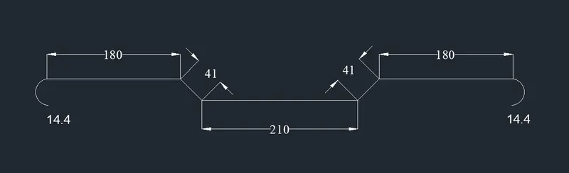
Step 3: (C-16mm)
1. Select the Line tool by typing L or Line in the command box
2. Draw a line of length 210mm for a straight bar
3. Draw an inclined vertical line of 41mm on both edges at an angle of 45°
4. Draw an extended horizontal line on both sides of a length of 180mm
5. Create it as a Block and give the block name as C-16mm
Step 4: (D-12mm)
1. Select the Line Command by typing L or Line in the command box
2. Draw a line of length 750mm for a straight bar
3. Select the Arc tool and create an arc to bend downwards at both corners
4. Create it as a Block and give the block name as D-12mm
Step 5: (E-10mm)
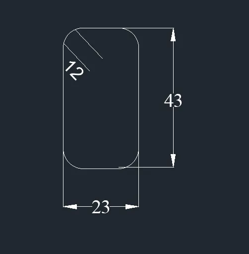
1. Select the Rectangle tool by typing REC or Rectangle in the command box
2. Draw a rectangle of dimension 23 x 43
3. Select the Fillet tool and fillet the corners with a radius of 15mm
4. Draw two lines inclined of length 120mm at the left corner as shown in the figure below
5. Create it as a Block and give the block name as E-10mm
Step 6:
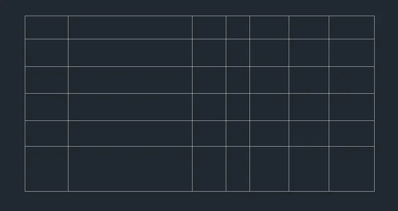
1. Select the Rectangle tool by typing REC or Rectangle in the command box
2. Draw a rectangle to show the table as shown in the figure
3. Select the Offset tool and Offest the lines according to position
Step 7:
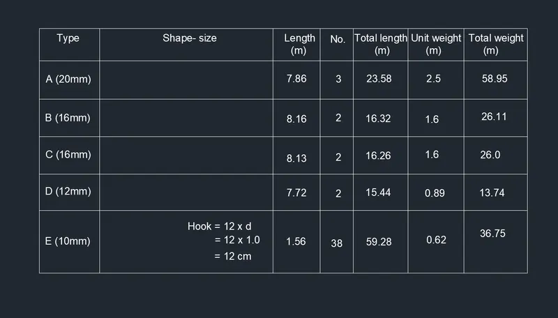
1. Select Multiline Text and type text as per the drawing
2. Select the Move tool by typing M or Move in the command box
3. Select the Text and Move it through the desired locations as shown in the figure below
4. Select the Copy tool by typing CO or COPY in the command box
5. Select the Text and Paste it through the desired locations
Step 8:
1. Open InsertBlock by typing I or Insert in the command box
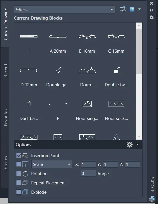
2. Insert all the bars into the screen as shown in the figure below
RESULT: