Creating Levels, Grids, Layout and model elements for a residential unit using REVIT
Creating Levels, Grids, Layout, and model elements for a residential unit using REVIT
1) What is BIM? Summarize the features of BIM and the benefits of using BIM over 2D CAD tools.
Answer:
BIM:
BIM is an acronym for Building Information Modeling or Building Information Management. It is a highly collaborative process that allows architects, engineers, real estate developers, contractors, manufacturers, and other construction professionals to plan, design, and construct a structure or building within one 3D model
BIM is used for creating and managing data during the design, construction, and operations process. BIM integrates multi-disciplinary data to create detailed digital representations that are managed in an open cloud platform for real-time collaboration. Using BIM gives you greater visibility, better decision-making, more sustainable options, and cost savings on AEC projects.
Features of BIM:
The main features of BIM are - (a) Coordination and (b) Computation.
Coordination: Revit as one of the BIM tools helps in achieving coordination between various disciplines associated with a construction project.
The different project teams while working on their individual design/models can come together and collectively achieve progress in a project as a whole. Autodesk REVIT aids this project coordination which is a key feature of Building Information Modelling.
Computation: REVIT as a BIM tool helps in producing Material schedule, Quantity schedule as well as performing Structural analysis and energy analysis of the building. Autodesk CFD provides fluid flow and thermal computations, specific to mechanical engineers, which helps to predict and optimize the performance of the structure.
Benefits of using BIM over 2D CAD tools:
There are great benefits of using BIM over 2D CAD tools
1. BIM offers a more complete representation of a building's design. It takes more than the building's core components into account. For example, BIM allows you to design electrical and HVAC systems, as well as the building itself. This means the project team can take full advantage of the space and resources available.
2. BIM pulls your documents into a single database. Several people can work on the same model and save it to the cloud. This allows for instant updates, so you won't waste time searching for documents when you need to make changes.
3. A BIM model will allow you to prefabricate important components ahead of time. You won't have to adjust them based on the building design. Instead, such components are part of the initial design.
4. You can provide much more to your clients using BIM than you could with CAD. The models you give to your clients update constantly as you work on your project. Your client can check-in at any time, which leads to quicker approval for milestones and more efficient project development.
4. Resource tracking is a key component of BIM models. You'll be able to figure out how much of each resource you need during the design stage. This improves the flow and efficiency of construction.
2) Understand the concept of Categories, Families, Elements, and Instances in Revit. Go to Insert Tab, and choose a category. Pick a family and element. Understand the instances and insert them into the Revit model
AIM:
To understand the concept of Categories, Families, Elements, and Instances in Revit
INTRODUCTION:
First, we need to understand the concept of the Categories, Families, Elements, and Instances in Revit
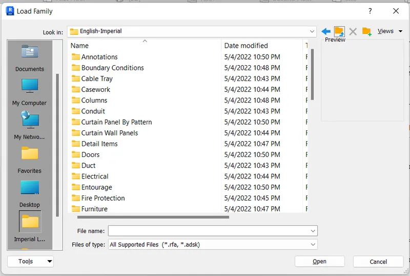
In the Insert toolbar, there is an option called Load Families. We can select the Categories, Families, Elements, and Instances by selecting load family

1. Categories:
Categories are the group of families in REVIT that are predefined by software.
A category controls the organization, visibility, graphical representations, and scheduling options of families within the project
Ex: Annotations, Columns, Doors, Furniture, etc.,
2. Family:
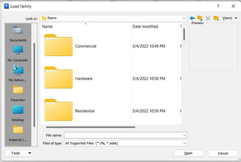
A Family is a group of elements with a common set of properties, called parameters, and a related graphical representation
A family is a grouping of 2D/3D information that serves to represent a discrete building or documentation element in the project.
Ex: Commerical, Residential, Hardware, etc.
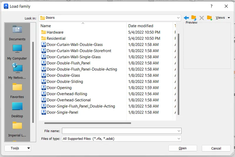
3. Element/Type:
The Type refers to a unique element that can be found under a family with specific characteristics.
In many cases, types represent different sizes/dimensions of the same family.
Ex: Under the single flush door family, we can find doors of different sizes like 30'x80', 36'x84', 36'x76' etc.,
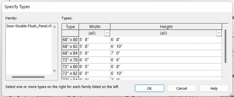
4. Instances:
Instances represent the individual graphical/ geometric elements placed in a Revit model
Every time a new type of element is added to the model, an instance is created and shown in the project
Ex: each single-flush door of the same size used in a model is an instance
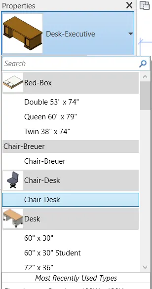
PROCEDURE:
Step 1:
1. Go to the start menu, click on Revit 2023
2. On the Home page, load the new model by clicking on New
3. In the New Project dialog box, select the desired template from the drop-down list
4. Create a New project and press Ok
Step 2:
1. Click on the Insert tab on the ribbon page
2. Click on the Load family option
3. In the Load family dialog box, browse to libraries
4. Next go to the US and select the Door Category
4. Select the door type that you want to insert
5. Select the type of door in the specified type dialog box
6. Select the Element in the Project browser and drag it to the desired location to create an instance.
RESULT:
The concept of understanding Categories, Families, Elements and Instances in Revit was clearly explained and it was inserted into the Revit model.
3) Setting up a Project – Open a project file with an architectural template. Save the file with an appropriate name. Set up the project units to Imperial / Metric based on your convenience of modeling. Complete the project information under the Manage tab. Set up the maximum backups for project files to 3
AIM:
To Create a new project and name the project appropriately
PROCEDURE:
Step 1:
1. Click on the Windows button and Type Revit to Open Revit software
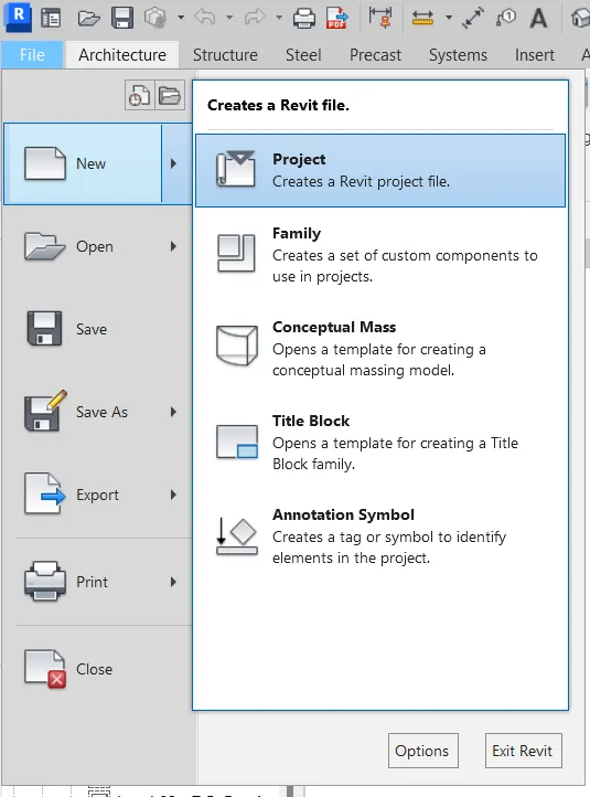
2. Once the Revit is opened, click on the File tab
3. In the file tab, Select New > Project and open the new project
Step 2:
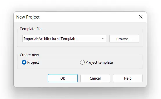
1. In the New Project dialog box, select the template file as Imperial- Architectural Template
2. Select Create new as Project option and open the project
Step 3:
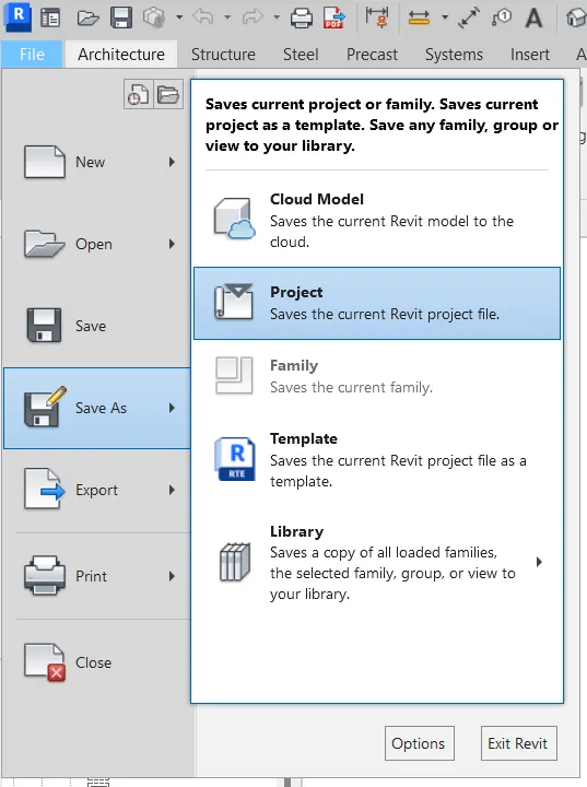
1. Save the new project file by clicking the save button in the File tab ( File > Save > Choose the folder that you want to save )
2. Give the New Project name Project-001
Step 4:
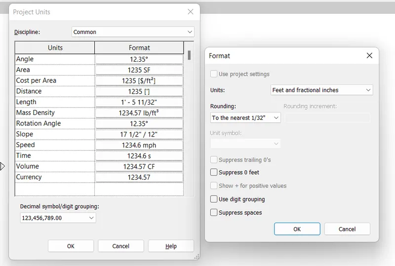
1. Open the project units dialog box by typing U or UN
2. Set the Units to Feet and Fraction inches and close the dialog box
Step 5:
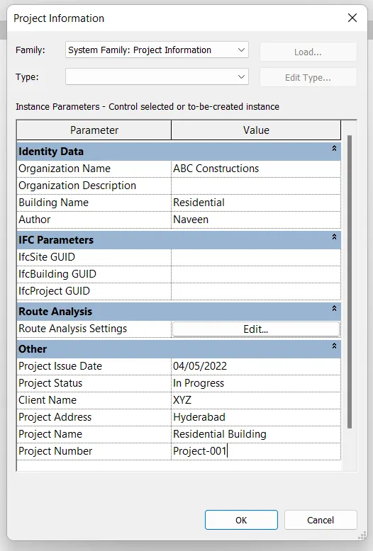
1. Click on the manage toolbar and select the project information option
Step 6:
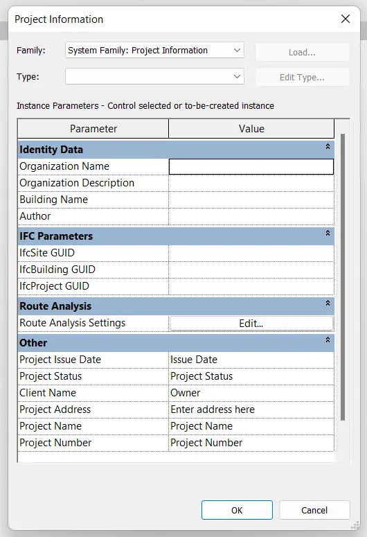
1. Give the necessary details such as organization name, building name
2. Type project issue date as of 04/05/2022 and project status as In progress
3. Type Client name as XYZ, Project Address as Hyderabad, Project name as Residential building, and Project number as Project-001
Step 7:
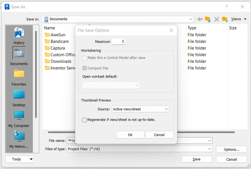
1. Click on the File tab and select the save option
2. Give the Project name as Project-001
3. Select the Options box in the right corner of the dialog box
4. Give maximum backup value as 3 and press Ok
5. Save it in the desired folder
RESULT:
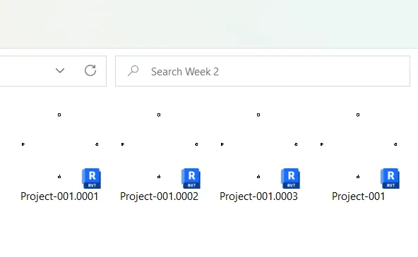
The project file is successfully set up and the procedure illustrated step by step how to open, save, set the Units, enter project information, and set the maximum number of backup files.
4) Understand the concept of Levels and Grids. Follow the naming and conventions. Create the following Levels: ( Convert to metric equivalents if the metric is your unit)
Ground Floor @ 0’
First Floor @ 10’
Second Floor @ 20’
Roof @ 30’
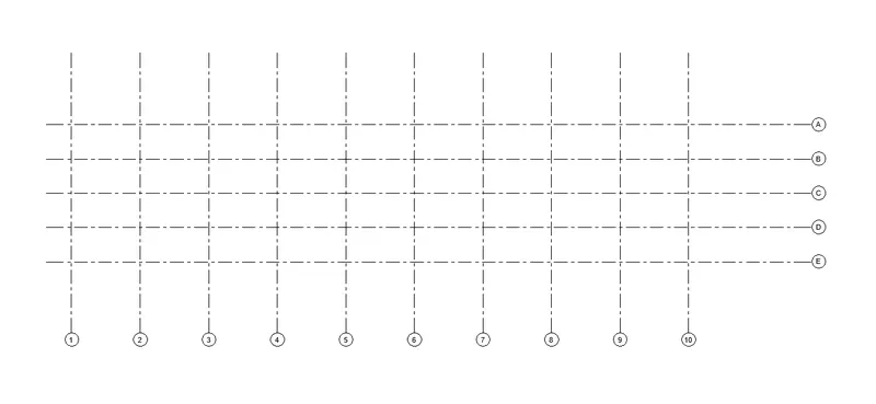
Grids Transverse Grids A, B, C, D, E @ 10’ spacing
Longitudinal Grids from 1 to 10 @ 20’ spacing
AIM:
To understand the concept of Levels and Grids. To create the levels and Grids according to that given data
INTRODUCTION:
The concept of Levels and Grids in Revit is explained and the procedure to create Levels and Grids in Revit following the naming and order convention is illustrated.
Levels and grids are finite planes and they help define project context. Levels and Grids act as reference points for all the model elements in a project.
Levels: A Level is a finite horizontal plane whose function is to act as a reference for elements such as roofs, floors, and ceilings. Levels indicate the location of the foundation, floors, and roof of a building in section and elevation views.
Grids: These are lines that represent finite planes. Using Grid several horizontal and Vertical lines (both curved and straight) can be created to divide the project space into smaller quadrangular units/cells. Gridlines help to organize the design and to locate the various elements within a project. The conventional practice of placing grids is either from right to left or left to right. We should stick to one particular type of convention for a given project. Additionally, Grids are placed in increments of numbers or alphabets.
PROCEDURE:
Step 1:
1. Click on the Windows button and Type Revit to Open Revit software
2. Once the Revit is opened, click on the File tab
3. In the file tab, Select New > Project and open the new project
4. Select the template as architectural and click ok
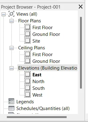
5. Go to Project browser and select the east view in elevation
Step 2:
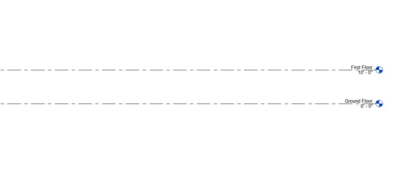
1. By default it shows two levels
2. Change the name of the levels to Ground Floor and first floor
Step 3:
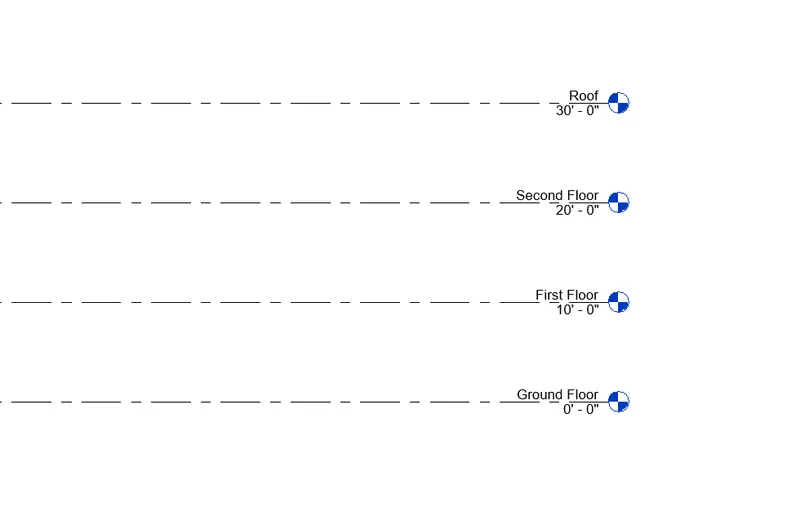
1. Go to the Architectural tab and select the Add levels option
2. Give the offset distance as 10'
3. Select the previous level and add another two levels
4. Change the name of the levels as Second floor and roof respectively
Step 4:
1. Now we have to create the grids on the floor plan
2. Go to Project browser, and select the ground floor in the floor plans
3. Go to the Architectural tab and select the grid option
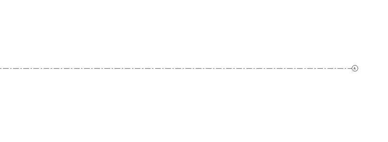
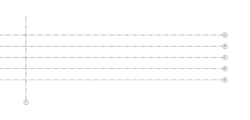
4. Create the horizontal grid from the left to right as shown in the figure below
Step 5:
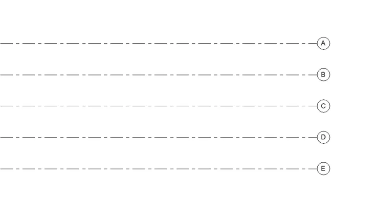
1. Select the grid tool again and give the Offset distance as 10'
2. Select the previous grid and create respective grids at the interval distance of 10'
3. Change the names of the grids lines as A, B, C, D, and E respectively
Step 6:
1. Go to the Architectural tab again and select the grid option
4. Create the vertical grid line from the top to the bottom screen as shown in the figure below
Step 7:
1. Select the grid tool again and give the Offset distance as 20'
2. Select the previous grid and create respective grids at the interval distance of 20'
3. Change the names of the grids lines to 1,2,3,4,5,6,7,8,9 and 10 respectively
RESULT:
The levels and the grid lines are created successfully in the Revit Model
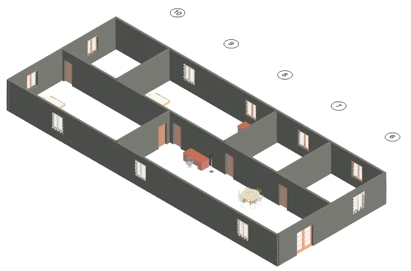
5) 3D modeling of the residential unit – From looking at your house / or a place you aspire. Create a conceptual layout of the residential unit. You can measure using a tape or
you can access your residential plan to create a similar layout.
AIM:
To create a conceptual layout of the residential unit in the Revit
INTRODUCTION:
The procedure of how to create a conceptual layout of the residential unit in Revit is explained in step by step procedure and the final result is given
PROCEDURE:
Step 1:
1. Open Revit Application and open the previous project that we created earlier
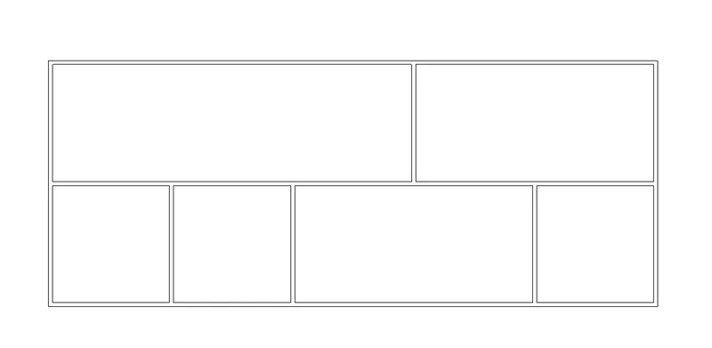
2. Go to the Architectural tab and select the Wall option as the default
3. From the Properties browser select the wall type as Generic 8' wall
4. Specify the location line as the grid point that we created earlier
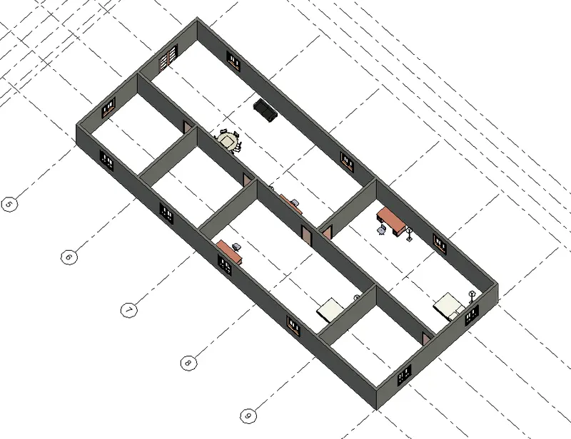
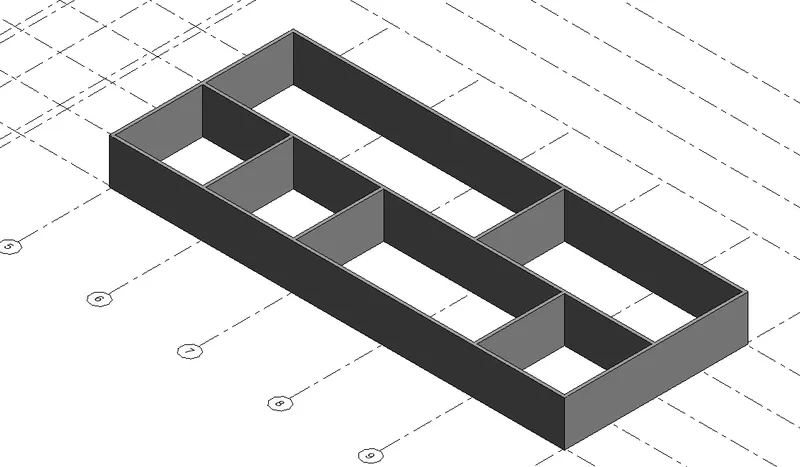
5. Draw the walls connecting the grids as shown in the figure below
Step 2:
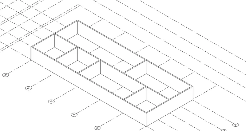
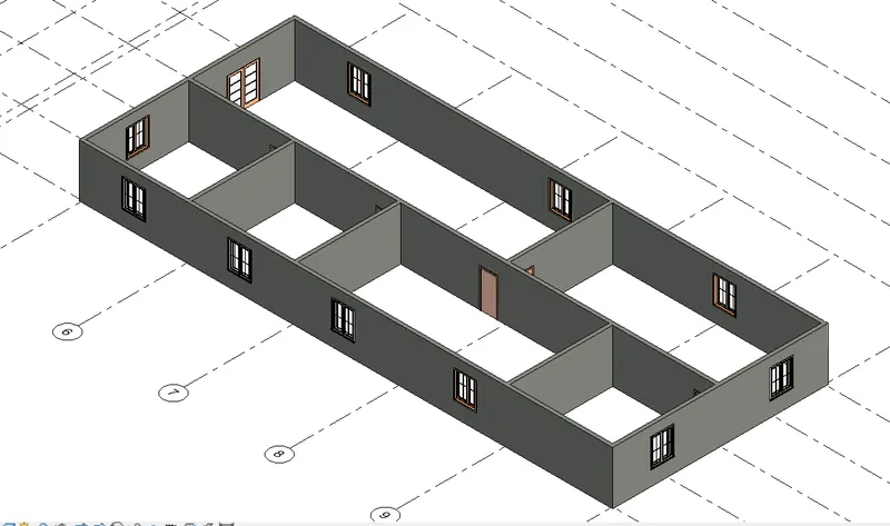
1. Go to 3D view and see the plan in 3D perspective
RESULT:
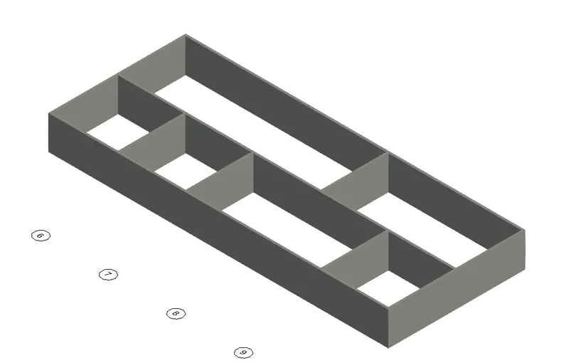
The conceptual layout of the residential unit has been created successfully
6) In the layout created draft the level of details you are planning to include – Dimensions of the room, and components you plan to add to the residential unit.
AIM:
To draft the level of details and to provide dimensions of the room, and components to the residential unit
INTRODUCTION:
The procedure of drafting details for the layout of a residential unit is explained by showcasing how to provide dimensions of the room and add components to the plan
PROCEDURE:
Step 1:
1. Open the project that we created earlier
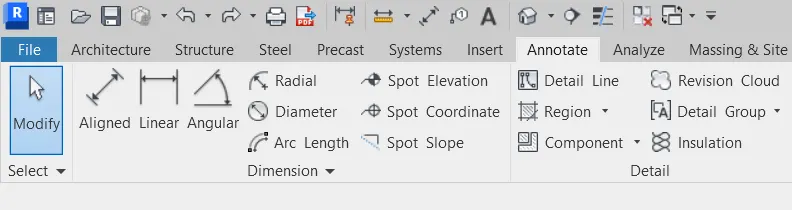
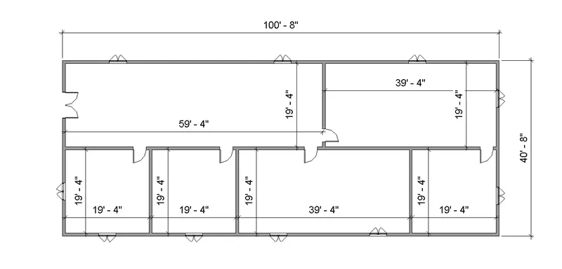
2. Go to Annotate tab and select the dimension tool as aligned
Step 2:
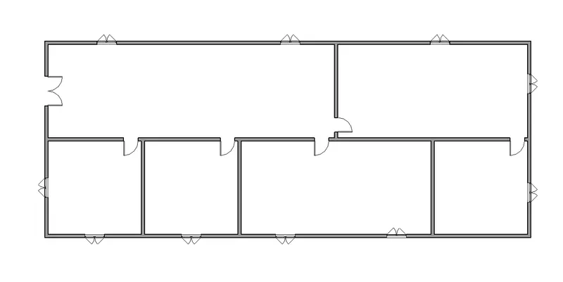
1. Go to the Architectural tab and select the door tool
2. Select the door as M- Double door Exterior
3. Place the doors at the desired location as shown in the figure below
4. Go to the Architectural tab again and select the window tool
5. Select the window as a Double window
6. Place the windows at the desired location as shown in the figure Below
Step 3:
1. Specify location line as Finish face: interior and Height as the first floor
2. Give the dimensions by clicking start point and endpoint
3. Do the same process for all the room dimensions as shown in the figure below
Step 4:
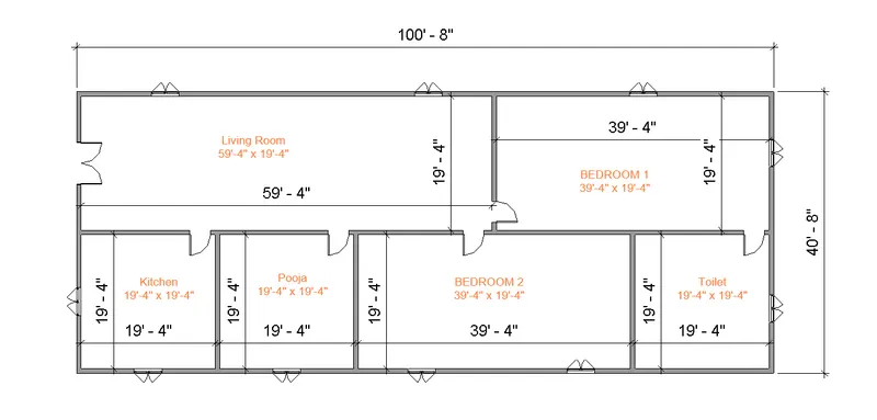
1. Go to Annotate tab and select the text tool
2. Place the text in the rooms at the desired location
3. Give the text as room dimensions as shown in the figure below
RESULT:
The details were added to the conceptual layout of the residential unit including the dimensions and sizes of the rooms
7) Identify the residential model elements such as Door, Windows, Tables, Chair, Couch, Bed, and Lamps from the library and insert them into the model
AIM:
To identify the residential model elements such as Doors, Windows, Tables, Chairs, Couch, Beds, and Lamps from the Library and insert them into the model.
INTRODUCTION:
The procedure of identifying elements from the library and inserting them into the model in Revit is explained in step by step procedure with the result
PROCEDURE:
Step 1:
1. Open the project that we created earlier
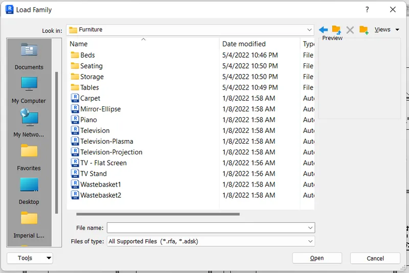
2. Go to the Insert tab and select the load family option
3. A load family dialog box will appear, go to the US and select the furniture category
Step 2:
1. Go to the Architectural tab and select the door tool
2. Select the door as M- Double door Exterior
3. Place the doors at the desired location as shown in the figure below
4. Go to the Architectural tab again and select the window tool
5. Select the window as a Double window
6. Place the windows at the desired location as shown in the figure Below
Step 3:
1. After loading the furniture into the Revit model, Select the Architectural tab and open the components option
2. Select the component as Desk- Executive and Select the size
3. Insert it through the screen at the desired location
Step 4:
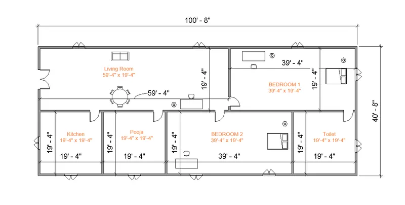
1. Similarly load the all the furniture that required using the Load family option
2. Select the size of the element as required
3. Place the furniture at the required position as shown in the figure below
RESULT:
The residential model elements such as Doors, Windows, Tables, Chairs, Couch, and Bed were identified from the library and inserted into the Revit model