Creating Architectural and Structural model with 3D rendering using REVIT
Creating Architectural and Structural models with 3D rendering using REVI
1) Select the type of structure you want to build from one of the three below:
a. Multi-Unit Residential Apartment
b. Office Buildings
c. School
Answer:
I have selected to design a Multi-Unit Residential Apartment
2) Assume reasonable assumptions for geographic and location details for your project modeling. Based on assumptions and type of structure selected identify the modeling requirements from NBC
Answer:
The geographical and location details for my project modeling based on the assumptions are listed below
1. My Residential Apartment is constructed in the urban area, Hyderabad, Telangana
2. It comes under the Group A - Residential Building- Subsection A5 as per NBC
3. The height of the Multi-Unit Residential building is 50'
4. The projected height in meters is 16m and the road width is 20m
5. The height, area limitation, and safety measures are followed according to National Building Code 2016
6. The thickness of the walls that I have chosen for Exterior and Internal walls are 9" and 6" respectively
7. The Size of the rooms also taken care of as per the NBC Part V-1
8. So, my project is completely safe and followed all the regulations according to the National Building Code 2016.
3) Using the structural model, include the following components based on the type of structure selected
a. Foundation – Isolated / Wall/Matt Foundation
b. Columns
c. Beams Connected to Columns
d. Roof Framing/ Truss
e. Floor / Decks
f. Floor Openings for Elevators and Stairs
AIM:
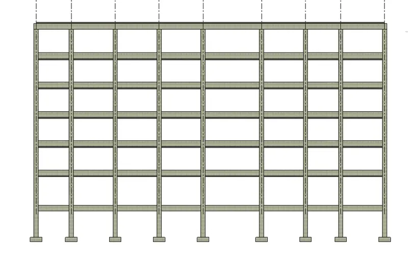
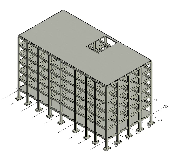
To create the structural model for the residential building including Columns, Beams, Roof Framing, Floor and Floor opening
INTRODUCTION:
Structural engineers need to be able to efficiently collaborate with all other teams during a project. Revit allows for just that by providing an intelligent model that is used by all stakeholders in real-time.
Revit is a native BIM solution, which means that all work is done on a single file that is constantly updated. By using such integrated workflows, structural engineers can ensure that no data is lost and minimize the risk of errors.
PROCEDURE:
Step 1:
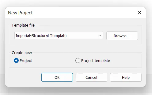
1. Open the Revit Software and Click on the new project
2. Select the template file as Imperial- Structural template
Step 2:
1. After opening the Structural template, now we have to create the basic grids and levels
2. Go to the Structural tab and select the levels tool
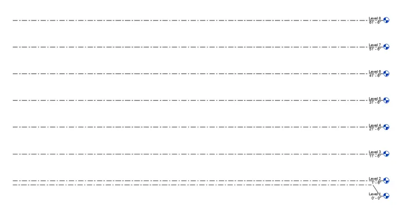
3. Create the level 2 at a distance of 2' from the level 1 to level 2
4. Same as create other levels at a distance of 10' from level 2 to level 8 as shown in the figure below
Step 3:
1. Now we have to create the basic grids for the project's shared coordinates
2. Go to the Structural tab and select the grids tool
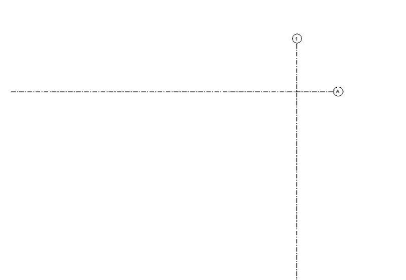
3. Create the Horizontal and vertical grids intersecting each other as shown in the figure below
Step 4:
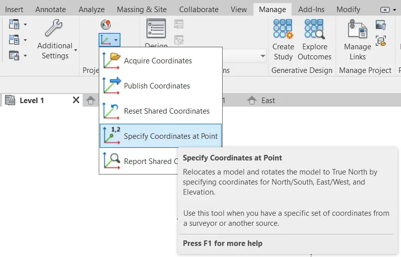
1. After creating grids, now we have to specify the coordinates at a point
2. Go to the Manage tab and select the project coordinates at a point option
Step 5:
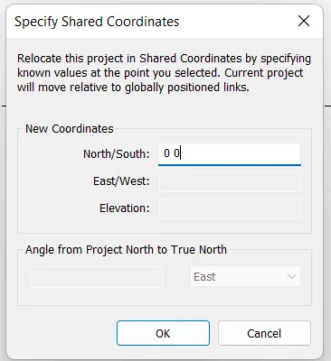
1. Select the intersecting point of grids and specify the new coordinates as 0' 0" for North/South
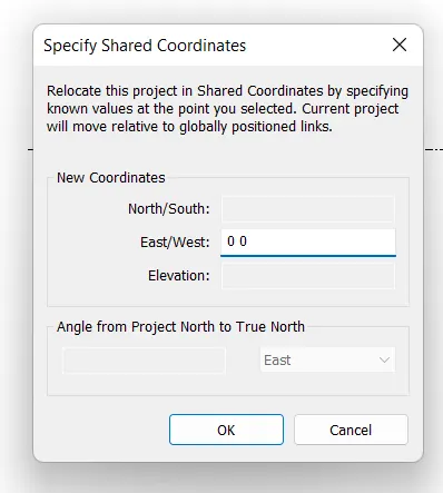
2. Similarly specify the new coordinates as 0' 0" for East/West
3. After specifying the coordinates, click ok
Step 6:
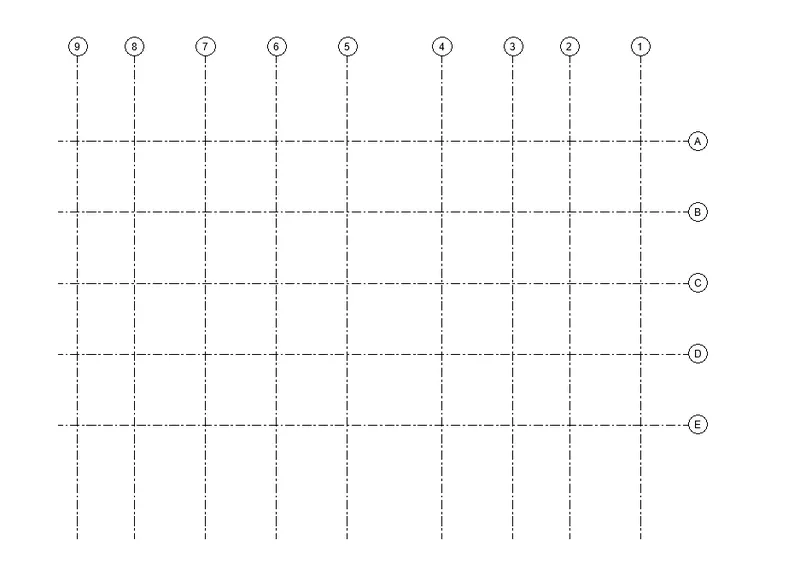
1. Now we have to create other grids for reference to sketch the columns and beams
2. Go to the Structural tab and select the grid tool
3. Create the grids Horizontally and transversely as shown in the figure below
Step 7: (Columns)
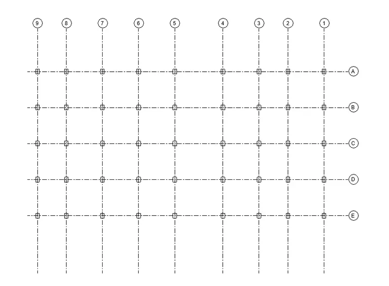
1. Now we have to create the columns at the grids level
2. Go to the Structural tab and select the column tool
3. Select the size of the Column as per the requirement
4. In the modify tab, select the option called at the grids level
5. Select all the grids and click on the tick mark
6. The columns have been created successfully at the grids level.
Step 8: (Beams connecting columns)
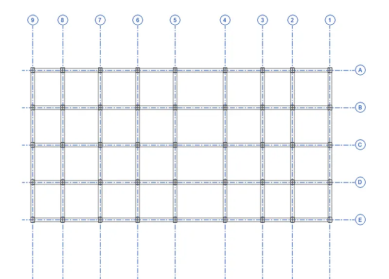
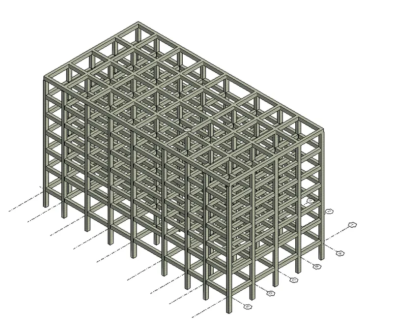
1. After creating columns, now we have to create the beams connecting columns
2. Go to the Structural tab and select the beam tool
3. Select the size of the beam as per the requirement
4. In the modify tab, select the option called at the grids
5. Sketch the beams at the intervals of each column as shown in the figure below
6. The beams connecting columns have been created successfully
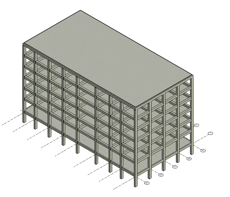
Step 9: (Floor and Roof)
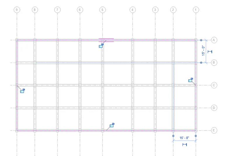
1. After creating the columns and beams, we have to create the floor and roof
2. Go to the Structural tab, select the structural floor tool
3. In the modify tab, select the rectangle tool to sketch the floor
4. Sketch the roof at the corners of the building as shown in the figure below
5. Similarly, sketch the roof at the top floor level
6. The structural floor and roof as been successfully created
Step 10: (Foundations)
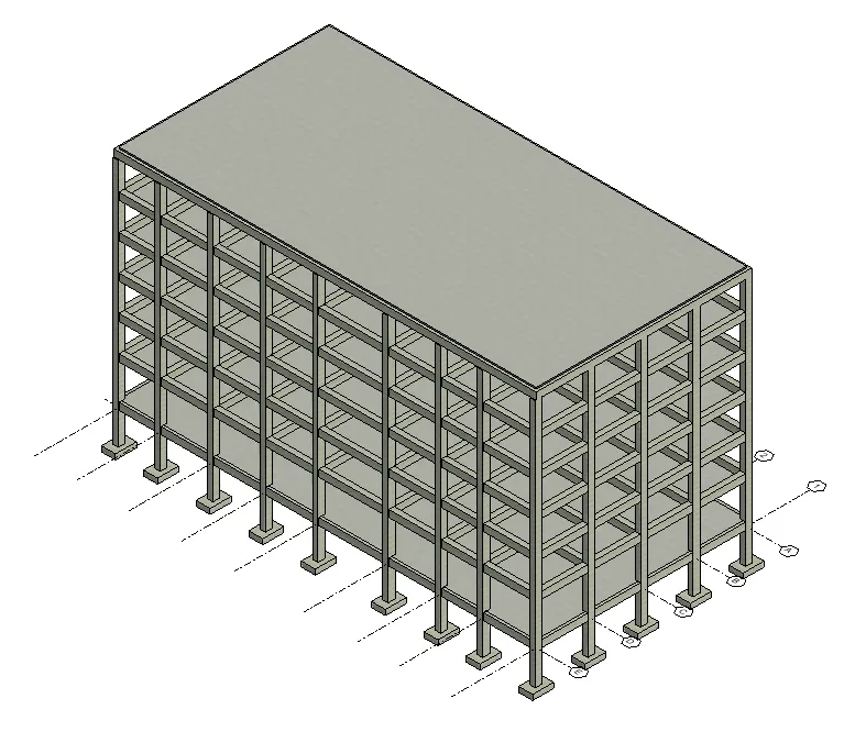
1. Go to the Structural tab, select the isolated footing under the foundation tab
2. Select the size of the footing as per the requirement
3. In the modify tab, select the grids option to create the footings
4. Select all the grids Horizontally and transversely
5. After Selecting the grids, Click on the tick mark to create the footings
6. All the Isolated Footings have been created successfully at the columns
Step 11: (Shaft Opening for Staircase)
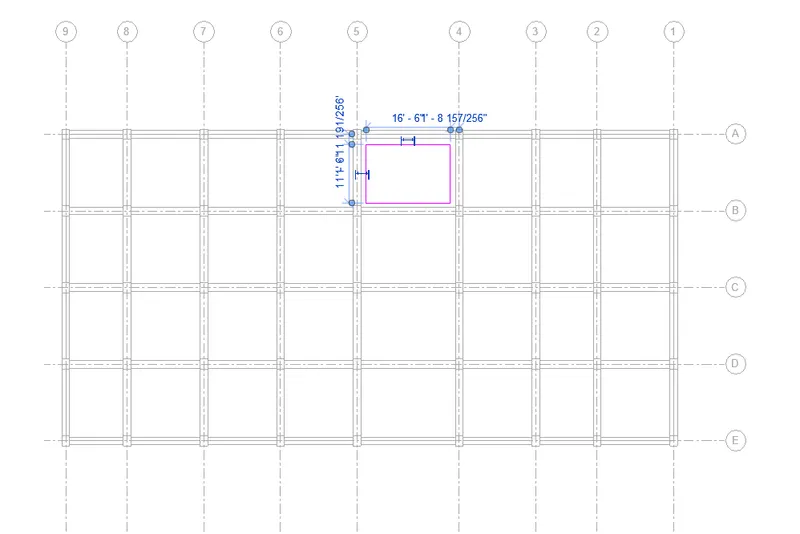
1. We have to create the shaft opening for all the levels to sketch the staircase
2. Go to the Structural tab and select the shaft opening tool
3. In the modify tab, select the rectangle tool to sketch the shaft opening
4. Sketch the shaft opening carefully as shown in the figure below
5. The shaft opening for all the levels has been created successfully
RESULT:
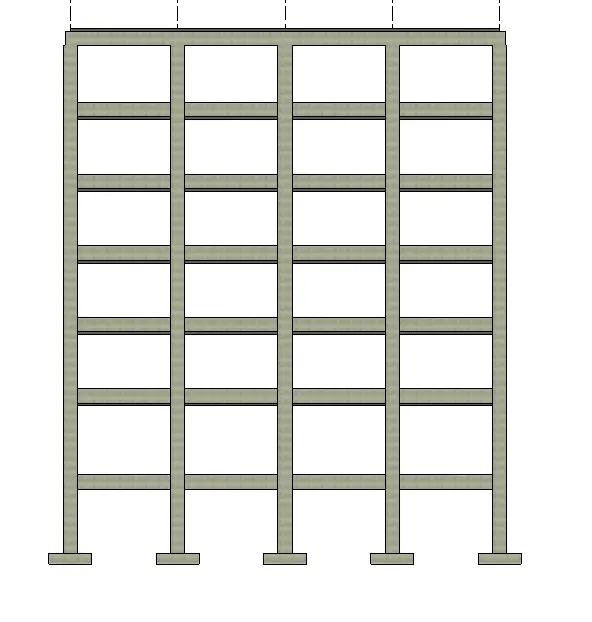
All the Structural elements such as foundations, columns, beams, floor, roof, and shaft opening for the staircase have been sketched and created successfully.
4) Using the architectural model, include the following components based on the type of structure selected
a. Wall Layout with appropriate material and finishing
b. Exterior façade with fancy finish
c. Interior partition walls to size rooms
d. Components to add details to a room ( Desk, Chair, Lighting, Plumbing fixtures)
e. Add components such as stairs Elevators
f. Have at least one side of the building with curtain walls and glass panels
g. Include interior and exterior lighting fixtures
h. Place proper topographic components from outside ( Trees, Parking, Plants) to add details to the model
AIM:
To create the architectural model of the residential building including walls, components, and other elements
INTRODUCTION:
An architectural model is a scale model – a physical representation of a structure – built to study aspects of an architectural design or communicate design ideas.
Depending on the purpose, models can be made from a variety of materials, including blocks, paper, and wood, and at a variety of scales.
PROCEDURE:
Step 1:
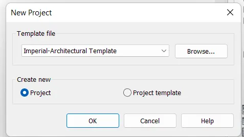
1. Open the Revit software and click on the new project
2. Select the template file as Imperial-Architectural Template
Step 2:
1. Now we have to create the basic grids to specify project shared coordinates
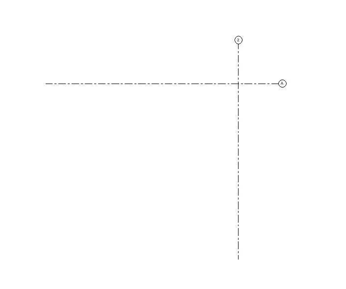
2. Go to the Architectural tab, select the grid tool option
3. Create the grids Horizontally and transversely intersecting each other as shown in the figure below
4. Specify the coordinates as 0' 0" for North/South and 0' 0" for East/West
Step 3:
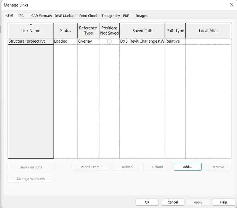
1. Now we have to link the Structural model to the Architectural model
2. Go to the Insert tab and select the option called Link Revit
3. Select the Structural file that we created earlier and load it into the architectural template
Step 4:
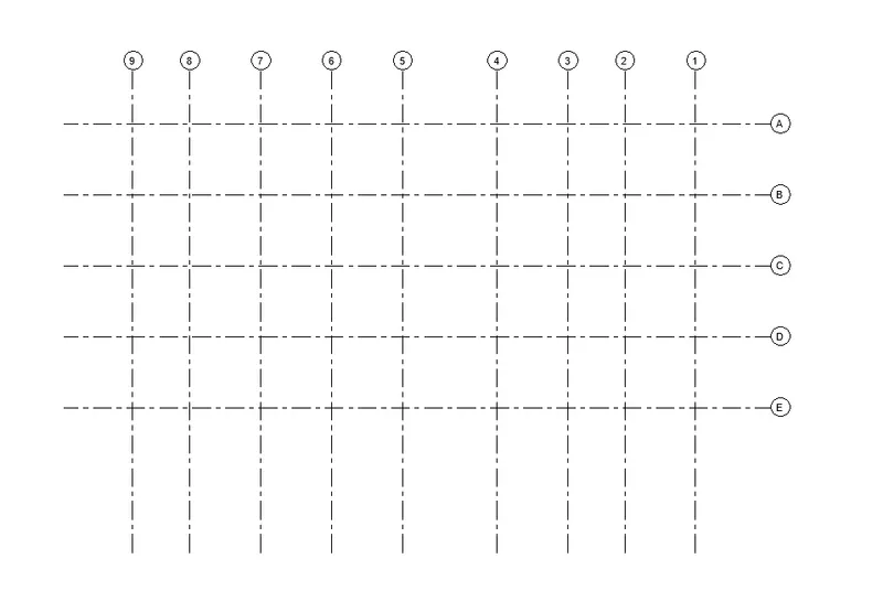
1. Select the grids and levels of the structural model
2. Copy them and paste them into the architectural template using copy and paste from the clipboard tool
Step 5: (Wall Layout)
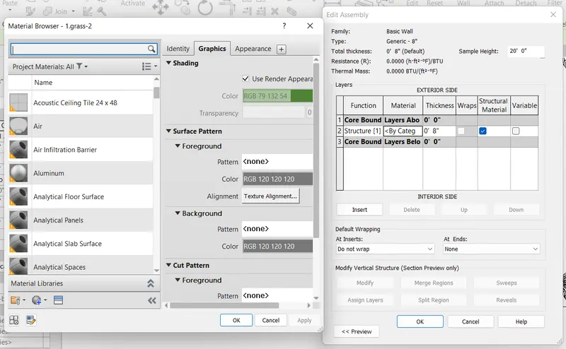
1. Now we have to create the walls with appropriate material and thickness
2. Select the wall and click on edit type in the properties browser
3. Select the appropriate wall thickness and material as per the requirement
4. I selected the wall thickness as 9" for exterior walls and 6" for interior walls
5. And then selected the wall material as Brick wall
Step 6:
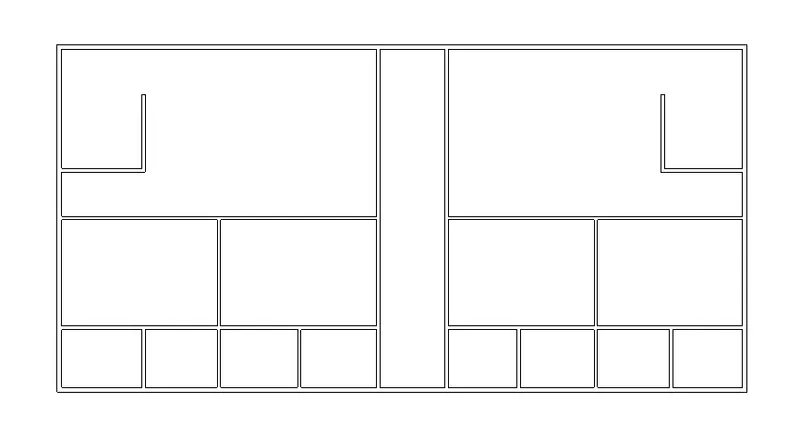
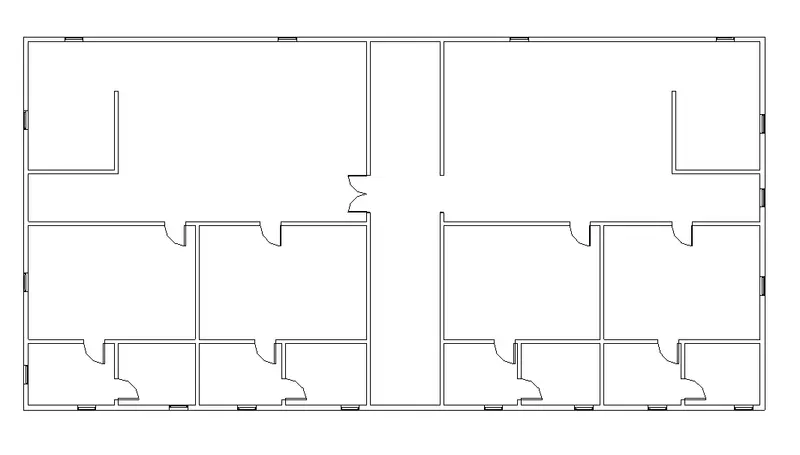
1. After Selecting the appropriate wall thickness and material, we have to sketch the floor plan
2. Select the 9" wall and start sketching the external walls
3. Now select the wall type as a 6" wall and sketch the interior walls
4. The floor plan using appropriate wall thickness and material has been created successfully as shown in the figure below
Step 7: (Doors and windows)
1. Now we have to provide doors and windows for the floor plans
2. Go to the Architectural tab and select the door tool
3. Select the appropriate size of the door as per the requirement
4. Place the doors at the desired location as shown in the figure below
5. Similarly select the window tool from the architectural tab
6. Select the appropriate size of the window as per the requirement
7. Place the windows at the desired location as shown in the figure below
Step 8: (Placing Components)
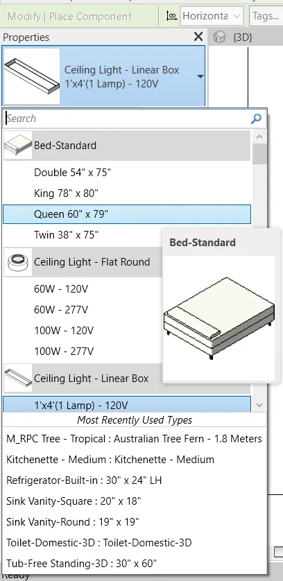
1. Go to the Architectural tab and select the components tool
2. Load the components from the library using the load family option
3. Select the appropriate components and place them in the appropriate rooms
Step 9:
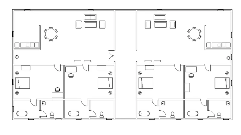
4. Place the beds and cabinets in the bedroom
5. Place the sofas and chairs in the living room
6. Place the countertop, stove, and other domestic components in the kitchen room
7. Place the bathtubs and urinals in the toilet room/bathroom
8. Similarly place the other components in the desired location as shown in the figure below
Step 10: (Sketching Staircase)
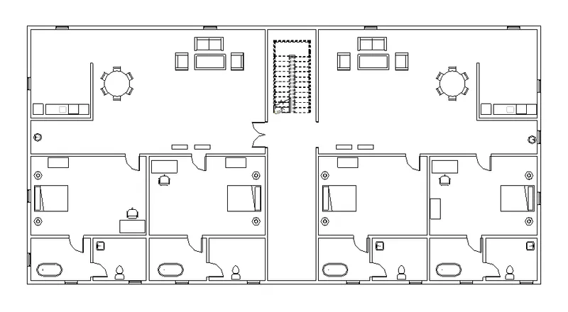
1. Now we have to sketch the staircase in the open shaft area
2. Go to the Architectural tab and select the staircase tool
3. Provide the number of Risers has Thread as per requirement
4. Select the Straight type and sketch the staircase carefully
5. The staircase has been created successfully at the shaft area
Step 11: (First Floor Plan)
1. Now we have to sketch the first floor and above plans for the residential building
2. Select the wall and click on edit type in the properties browser
3. Select the appropriate wall thickness and material as per the requirement
4. I selected the wall thickness as 9" for exterior walls and 6" for interior walls
5. And then selected the wall material as Brick wall
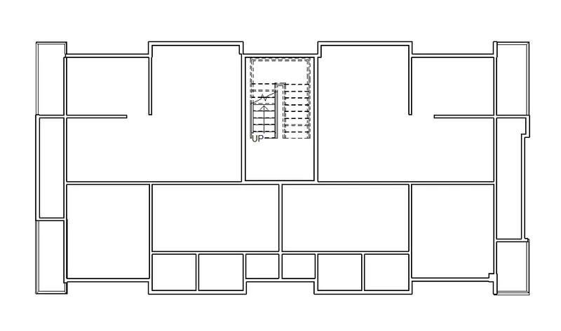
6. After Selecting appropriate wall thickness and material, we have to sketch the floor plan
7. Select the 9" wall and start sketching the external walls
8. Now select the wall type as a 6" wall and sketch the interior walls
9. The floor plan using appropriate wall thickness and material has been created successfully as shown in the figure below
10. Now we have to sketch the staircase in the open shaft area
11. Go to the Architectural tab and select the staircase tool
12. Provide the number of Risers has Thread as per requirement
13. Select the Straight type and sketch the staircase carefully
14. The wall layout plan staircase has been created successfully
Step 12: (Doors and windows)
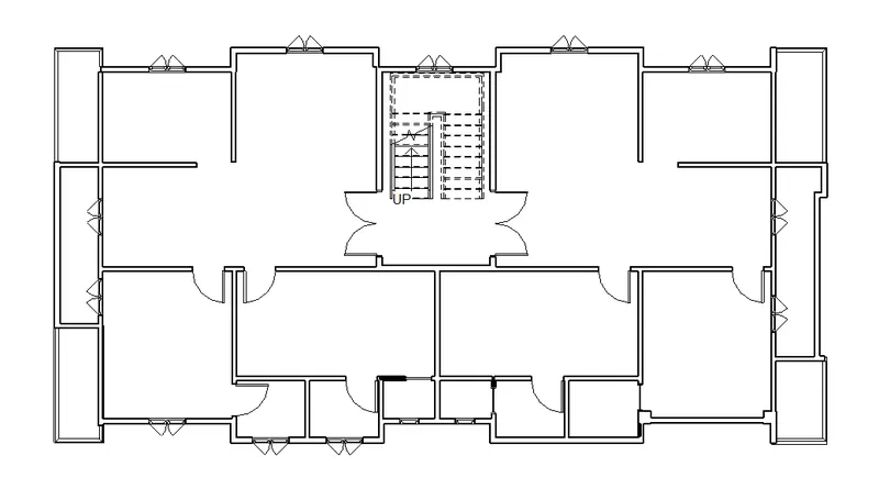
1. Now we have to provide doors and windows for the floor plans
2. Go to the Architectural tab and select the door tool
3. Select the appropriate size of the door as per the requirement
4. Place the doors at the desired location as shown in the figure below
5. Similarly select the window tool from the architectural tab
6. Select the appropriate size of the window as per the requirement
7. Place the windows at the desired location as shown in the figure below
Step 13: (Placing Components)
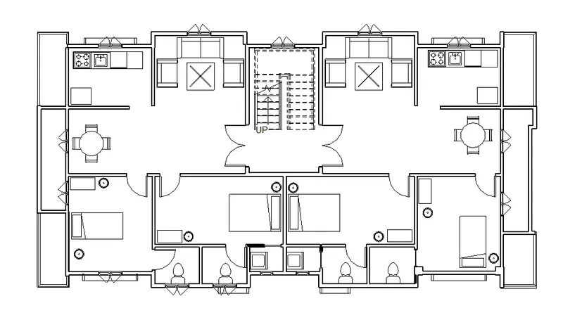
1. Go to the Architectural tab and select the components tool
2. Load the components from the library using the load family option
3. Select the appropriate components and place them in the appropriate rooms
4. Place the beds and cabinets in the bedroom
5. Place the sofas and chairs in the living room
6. Place the countertop, stove, and other domestic components in the kitchen room
7. Place the bathtubs and urinals in the toilet room/bathroom
8. Similarly place the other components in the desired location as shown in the figure below
Step 14: (Providing Interior and Exterior Lighting)
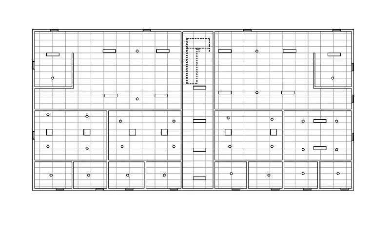
1. Now we have provided lighting fixtures in the interior rooms and exterior
2. We have to place interior lighting fixtures in the ceiling plan
3. Select the components tool in the architectural tab
4. Load the lighting fixture components into the model using the load family option
5. Select the lighting fixture and place it in the desired location in every room
6. After placing all the lighting components in the ceiling plan, now we have to place the lighting fixtures in the external layout
7. Select the lighting fixtures and place them on the balcony or outside the building
Step 15: (Topographical Components)
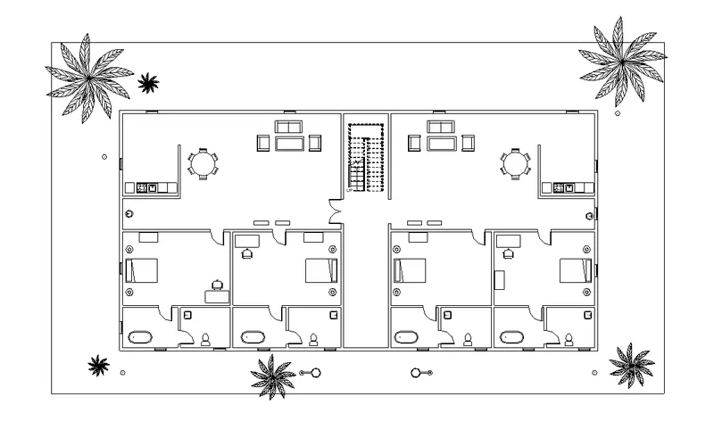
1. Now we have to add Topographical Components such as trees and massing site etc
2. Go to massing and site tab and load the topographic components from load families
3. After loading the component, select the components and place them on the exterior sides of the building as shown in the figure below
4. All the Topographical Components have been added to the model successfully
RESULT:
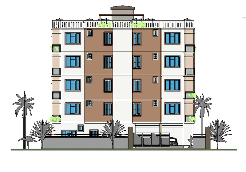
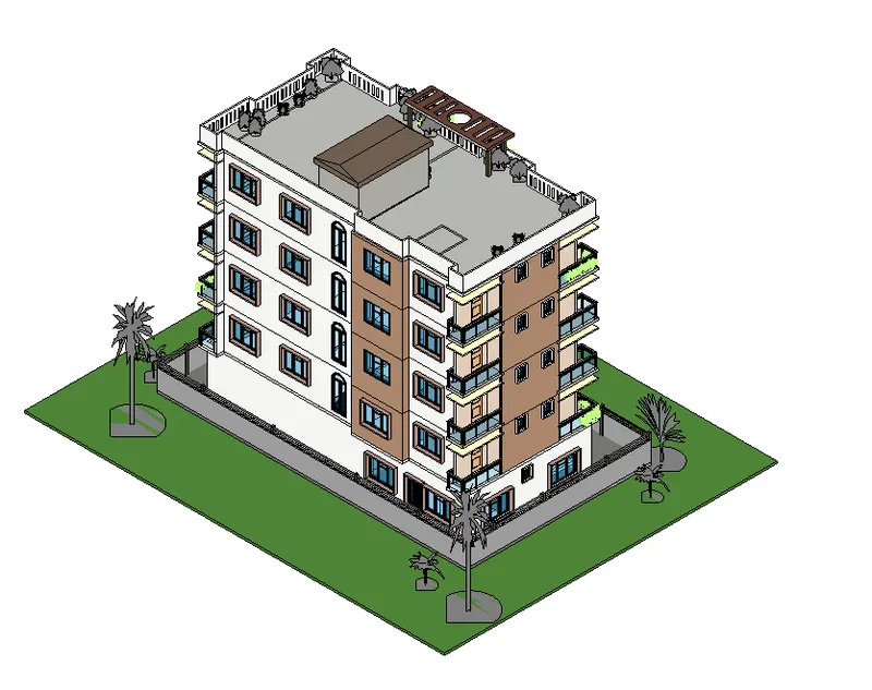
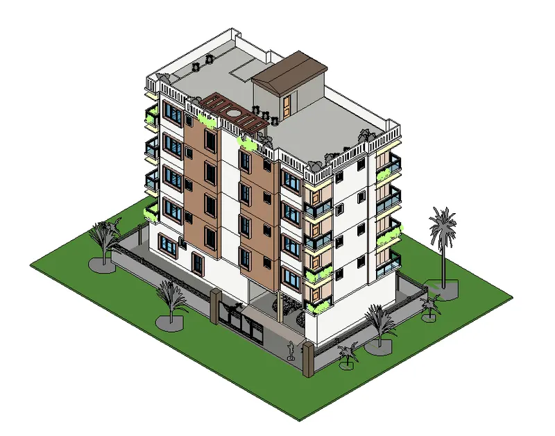
The Architectural model including wall layout, doors, windows, staircase, components, and lighting fixtures has been created and added to the plan successfully
5) Provide a set of drawings in an architectural and structural model to list the following details with categories and appropriate sheet templates included
a. Floor Plans with Annotations
b. Elevations
c. Sections
AIM:
To add the set of drawings from the architectural and structural model into the sheet templates
INTRODUCTION:
When creating a project template, we can include sheets in the template. Start with a blank project file, and create the standard views and levels that each project should include. Leave the views empty, but assign standard names to them.
Create sheets using the desired title blocks to create a standard set of construction documents. Add views to the sheets, using the desired viewport templates and view title types. Then save the empty project as a project template.
PROCEDURE:
Step 1:
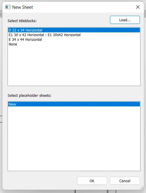
1. First we have to load the title block sheets into the model
2. Go to the View tab and select the sheet tool
3. Load the sheets into the model from the library
5. Select the appropriate sheet template as per the requirement
Step 2: (Architectural Plans)
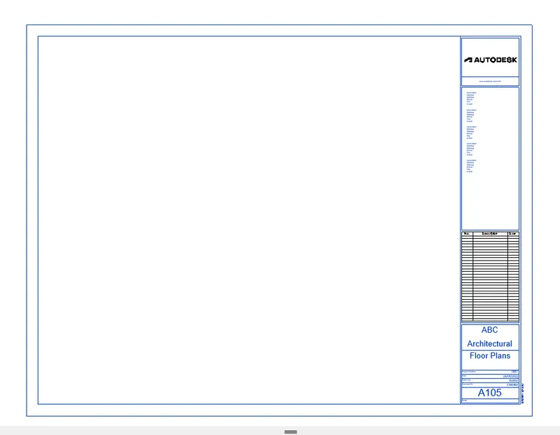
1. A New sheet template will open on the screen
2. Change the project information on the sheet template
Step 3:
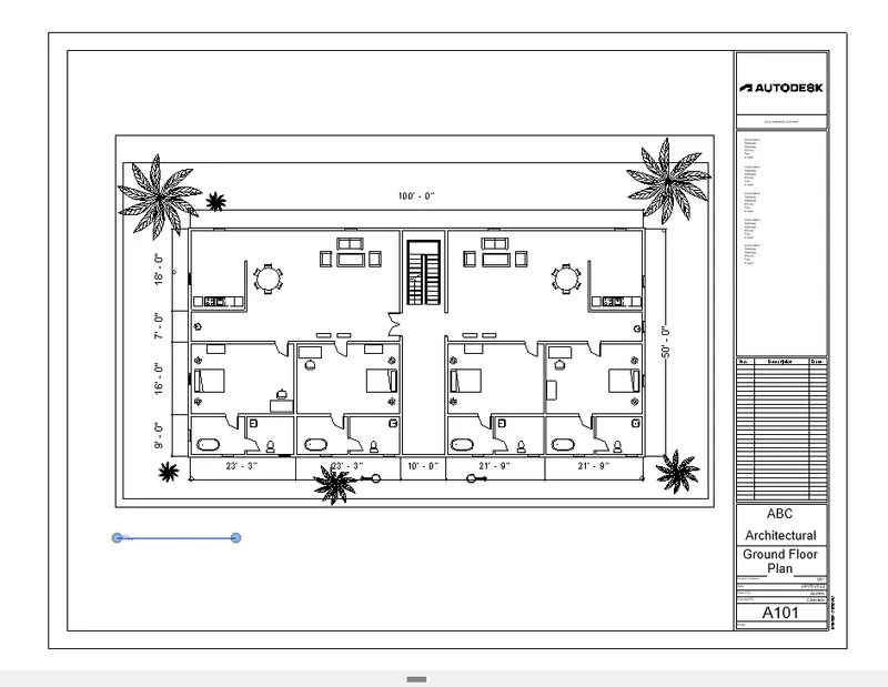
1. After Changing the project information on the sheet template, now we have to add the Architectural floor plans to the sheet
2. Select the ground floor plan from the project browser and drag it to the sheet template
3. Adjust the view scale option as per the requirement as shown in the figure below
Step 4:
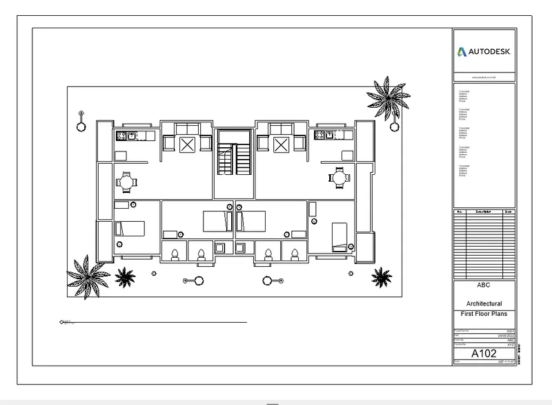
1. Now we have to add the first-floor plan into the New sheet template file
2. Select the first-floor plan from the project browser and drag it to the sheet template
3. Adjust the view scale according to the requirement as shown in the figure below
Step 5: (Structural Plans)
1. Select the appropriate sheet template from the view tab
2. A New sheet template will open on the screen
3. Change the project information on the sheet template
Step 6:
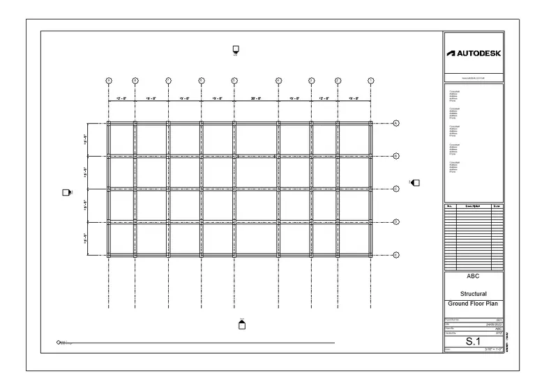
1. After Changing the project information on the sheet template, now we have to add the structural floor plans to the sheet
2. Select the ground floor plan from the project browser and drag it to the sheet template
3. Adjust the view scale option as per the requirement as shown in the figure below
Step 7:
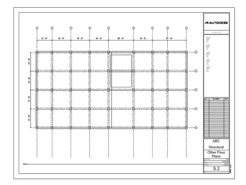
1. Now we have to add the first-floor plan into the New sheet template file
2. Select the first-floor plan from the project browser and drag it to the sheet template
3. Adjust the view scale according to the requirement as shown in the figure below
Step 8: (Elevation Views)
1. Select the appropriate sheet template from the view tab
2. A New sheet template will open on the screen
3. Change the project information on the sheet template
Step 9:
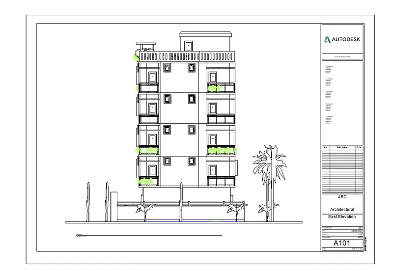
1. After Changing the project information on the sheet template, now we have to add all the elevations to the sheet
2. Select the East elevation from the project browser and drag it to the sheet template
3. Adjust the view scale option as per the requirement as shown in the figure below
Step 10:
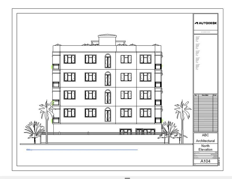
1. Now we have to add the North Elevation into the New sheet template file
2. Select the North Elevation from the project browser and drag it to the sheet template
3. Adjust the view scale according to the requirement as shown in the figure below
Step 11:
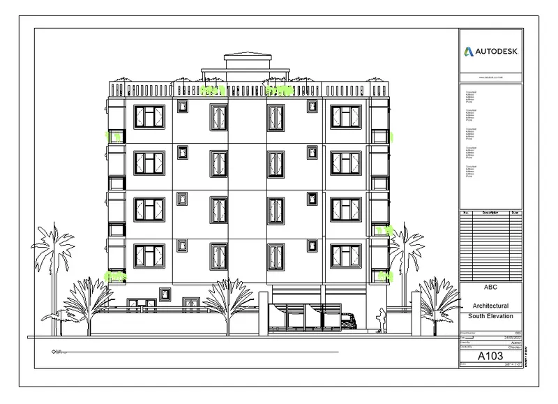
1. Now we have to add the South Elevation into the New sheet template file
2. Select the South Elevation from the project browser and drag it to the sheet template
3. Adjust the view scale option as per the requirement as shown in the figure below
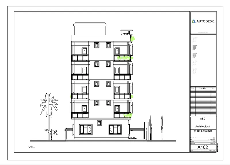
Step 12:
1. Now we have to add the West Elevation into the New sheet template file
2. Select the West Elevation from the project browser and drag it to the sheet template
3. Adjust the view scale according to the requirement as shown in the figure below
Step 13: (Sectional Views)
1. Select the appropriate sheet template from the view tab
2. A New sheet template will open on the screen
3. Change the project information on the sheet template
Step 14:
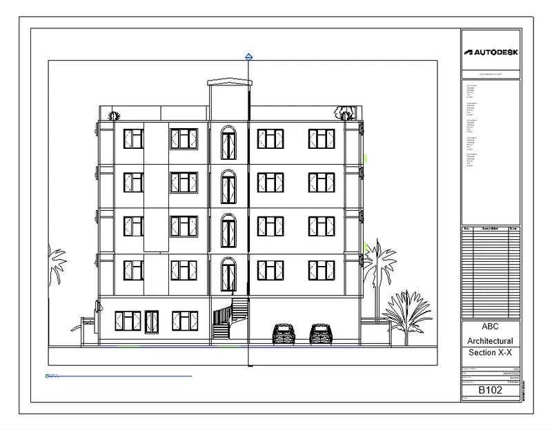
1. After Changing the project information on the sheet template, now we have to add all the Sections to the sheet
2. Select the Section X-X from the project browser and drag it to the sheet template
3. Adjust the view scale option as per the requirement as shown in the figure below
Step 15:
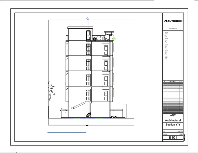
1. Now we have to add the Section Y-Y into the New sheet template file
2. Select the Section Y-Y from the project browser and drag it to the sheet template
3. Adjust the view scale according to the requirement as shown in the figure below
RESULT:
The Structural plans, Architectural plans, Elevations, and Sections have been successfully added to the appropriate sheet template
6) Using the Rendering settings, Render images of the 3D model produced and include the rendered images in the drawing sheets
a. Rendering from interior rooms
b. Rendering from out showing topographic features
c. Rendering through structural framing
AIM:
To add the Rendered images of the 3D model from interior rooms, topographic features, and structural framings into the sheet template
INTRODUCTION:
Autodesk Revit Render is the in-product rendering engine, allowing you to create high-quality rendered images and animations.
We can render 3D views from a model. You can then place rendered images on sheets to present designs to clients.
Lighting is an important factor in conveying the design intent. We can use rendering tools to set and adjust artificial lighting in your model.
In addition, we can include plants, cars, people, and other entourage in project views.
PROCEDURE:
Step 1:
1. First we have to render the images using the rendering tool
2. Open the 3D view that we want to render from the project browser
3. Go to the view tab and select the rendering tool
Step 2:
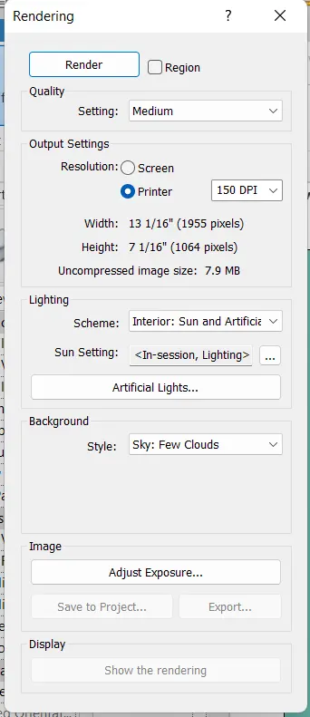
1. Adjust the rendering settings for convenient
2. Select the lighting settings and adjust the sun setting as per the requirement
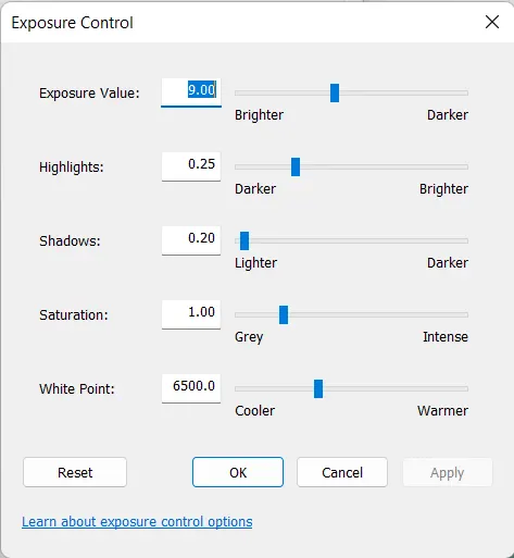
3. Now go to image adjust exposure and adjust the exposure brightness, highlights, shadows, saturation, etc., As per requirement
Step 3:
1. Now we have to load the title block sheets into the model
2. Go to the View tab and select the sheet tool
3. Load the sheets into the model from the library
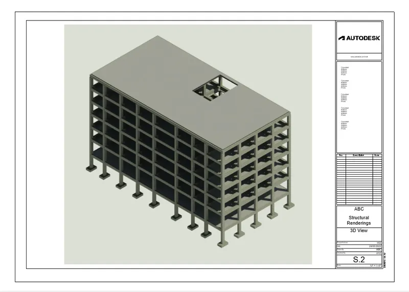
Step 4: (Structural Framings)
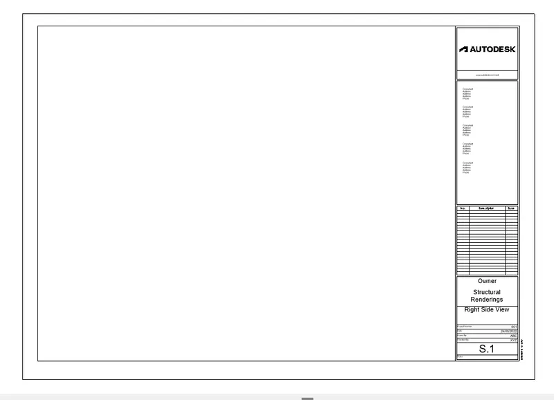
1. Select the appropriate sheet template from the view tab
2. A New sheet template will open on the screen
3. Change the project information on the sheet template
Step 5:
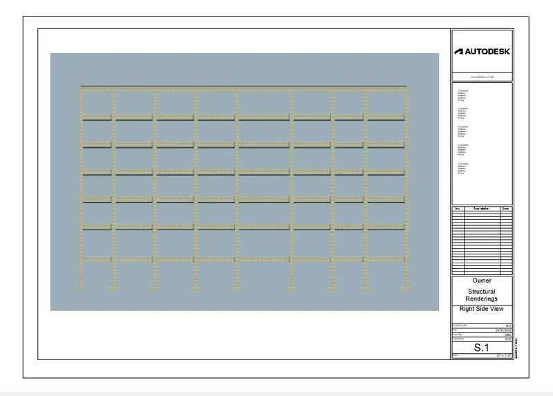
1. After Changing the project information on the sheet template, now we have to add all the Rendered images of the structural framings into the sheet
2. Select the Right side view of the structural framing from the project browser and drag it to the sheet template
3. Adjust the view scale option as per the requirement as shown in the figure below
Step 6:
1. Now we have to add the 3D view of structural framing into the New sheet template file
2. Select the 3D view from the project browser and drag it to the sheet template
3. Adjust the view scale according to the requirement as shown in the figure below
Step 7: (Interior Rooms)
1. Select the appropriate sheet template from the view tab
2. A New sheet template will open on the screen
3. Change the project information on the sheet template
Step 8:
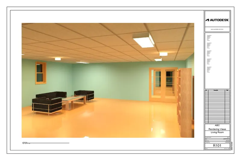
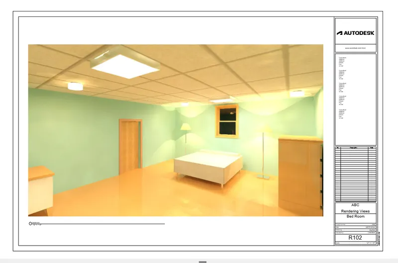
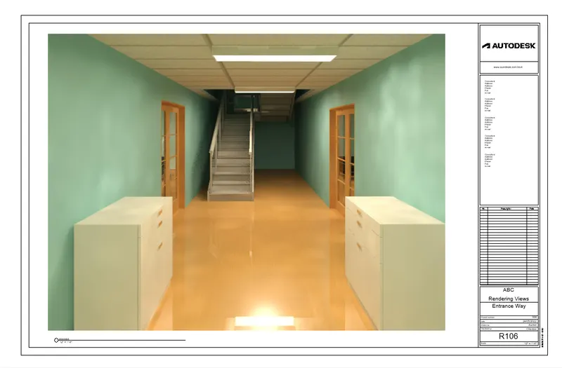
1. After Changing the project information on the sheet template, now we have to add all the Rendered images of interior rooms into the sheet
2. Select the appropriate views from the project browser and drag them to the new sheet template
3. Adjust the view scale option as per the requirement as shown in the figure below
- Living Room:
- Bed Room:
- Kitchen Room:
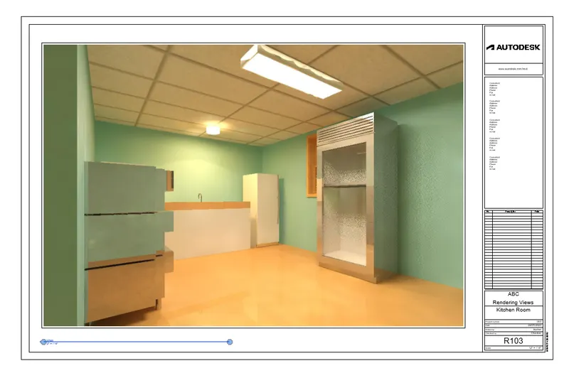
- Dinning View:
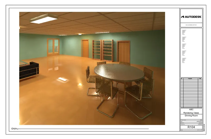
- Toilet Room:
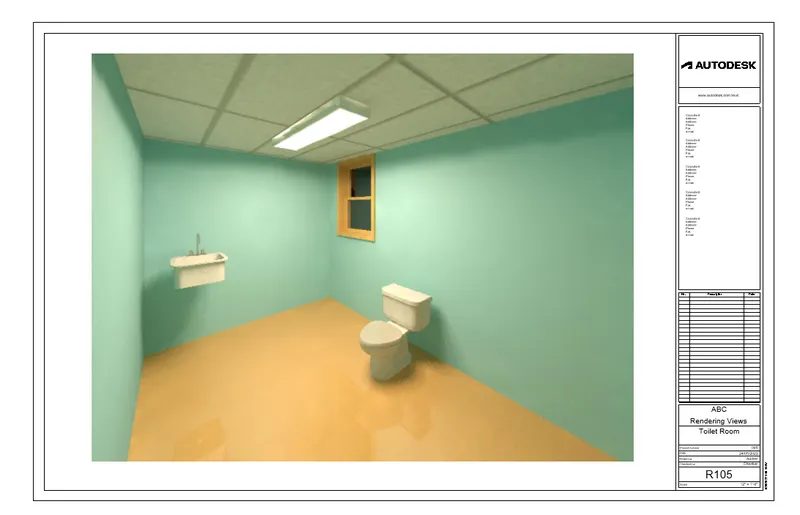
- Entrance View:
Step 9: (Topographic Views)
1. Select the appropriate sheet template from the view tab
2. A New sheet template will open on the screen
3. Change the project information on the sheet template
Step 10:
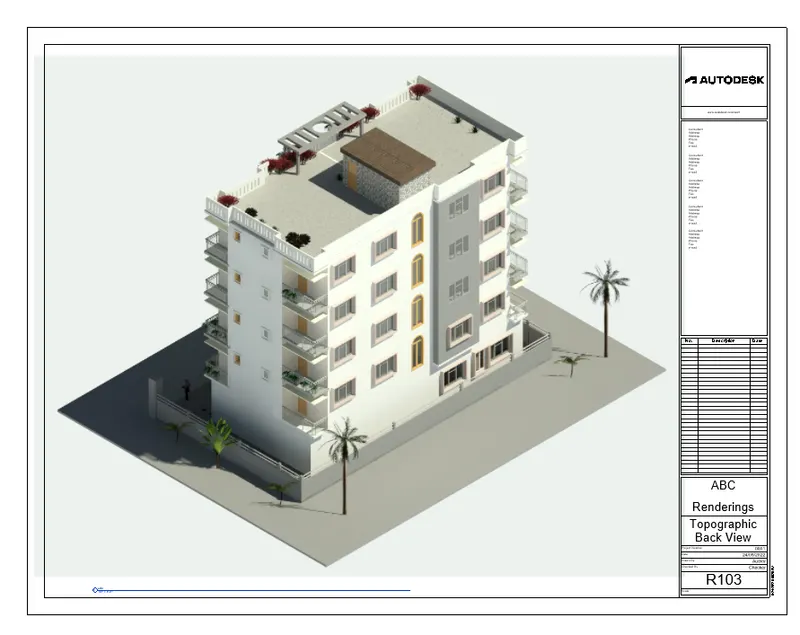
1. After Changing the project information on the sheet template, now we have to add all the Rendered images of topographic views into the sheet
2. Select the appropriate views from the project browser and drag them to the new sheet template
3. Adjust the view scale option as per the requirement as shown in the figure below
- 3D View 1: (South-East)
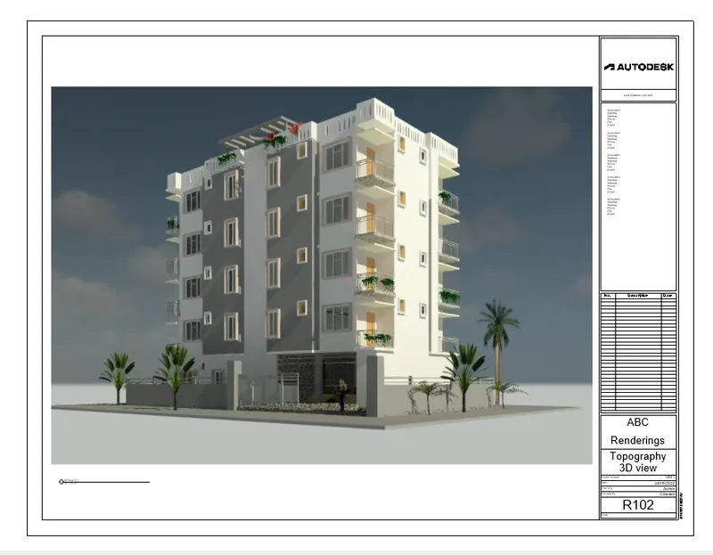
- 3D View 2: (East)
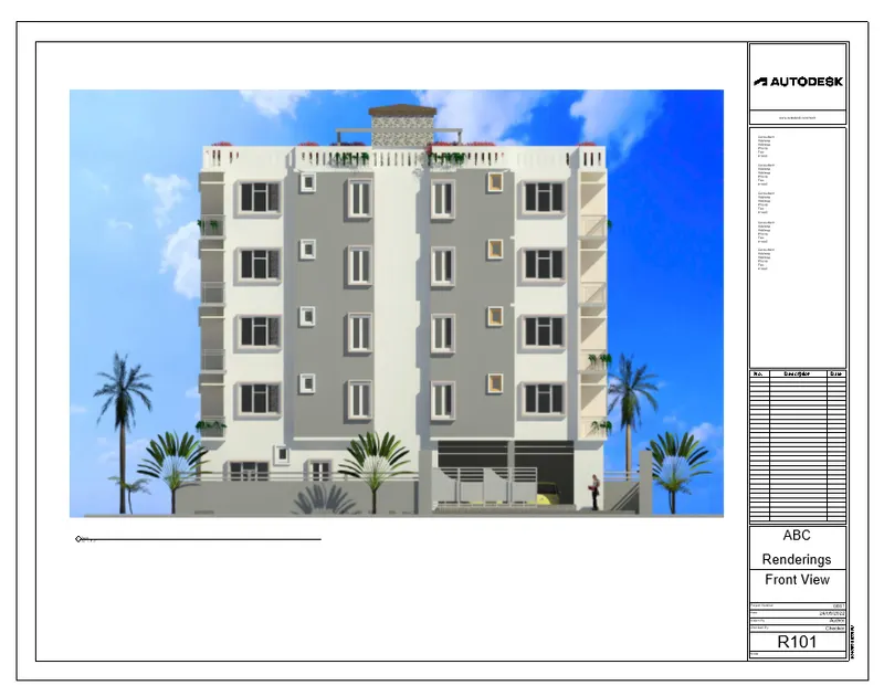
- 3D View 3: (North)
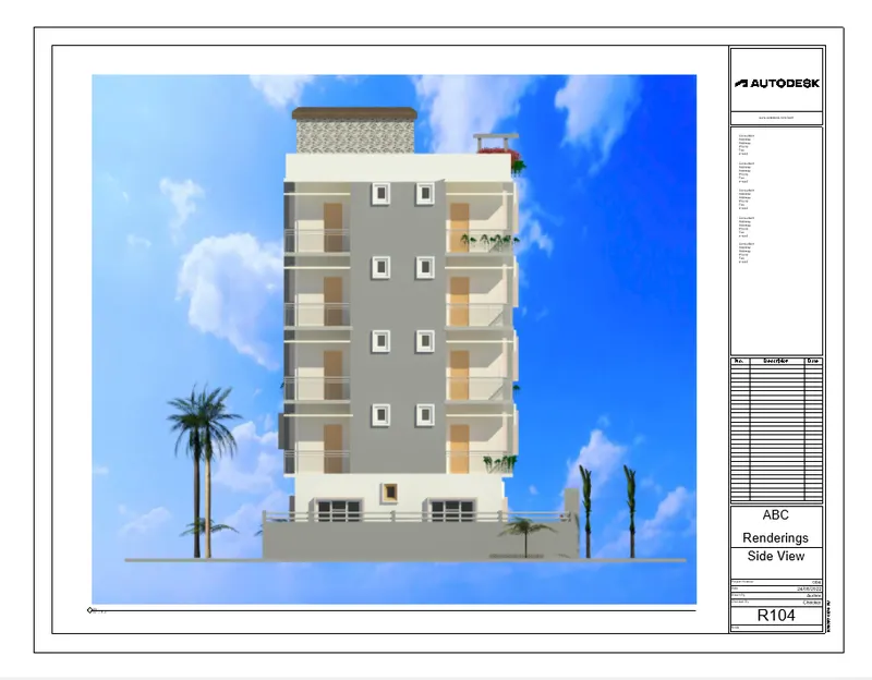
- 3D View 4: (North-West)
RESULT:
All the rendering images of Structural framings, Interior rooms, and Topographic views have been successfully rendered and inserted into the Sheet Template
7) Print the set of drawing sheets created and submit the drawings from the architecture and structure model
AIM:
To Print the Set of drawings sheets that we created from the architectural and structural model
INTRODUCTION:
In this project, we are going to take a look at Printing our Views and Sheets Once we have composed our Sheets by placing Views onto them, it is time to print them. When we click on the print option
The “Print” dialogue box opens. The panel is split into 4 main areas:
Printer Setup: Make your choice of output device here
Print Range: The most important part of the panel. More on this in a second
Options: Decide on the number of copies you need
Settings: Set defaults for paper size, orientation, etc. You can even save the configuration for use at another time
PROCEDURE:
Step 1:
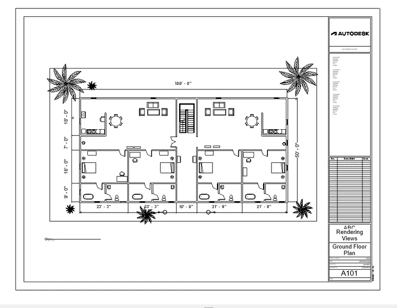
1. Before printing the sheet, we have to select the sheet that we want to print
2. Here I'm selecting the Architectural ground floor plan from the project browser
Step 2:
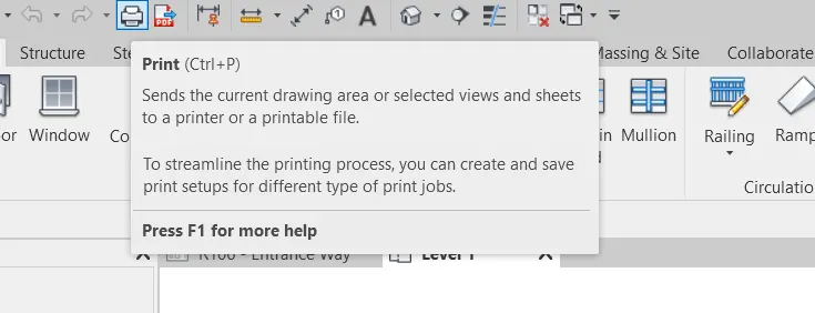
1. Now Select the print tool on the upper tab of the Revit software
2. We can use the shortcut key Cntrl+P to open the print dialog box
Step 3:
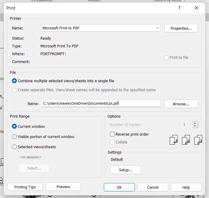
1. It will open the dialog box showing various settings
2. Choose the Mircosoft print to PDF option
3. Select the path storage that we want to save the file
Step 4:
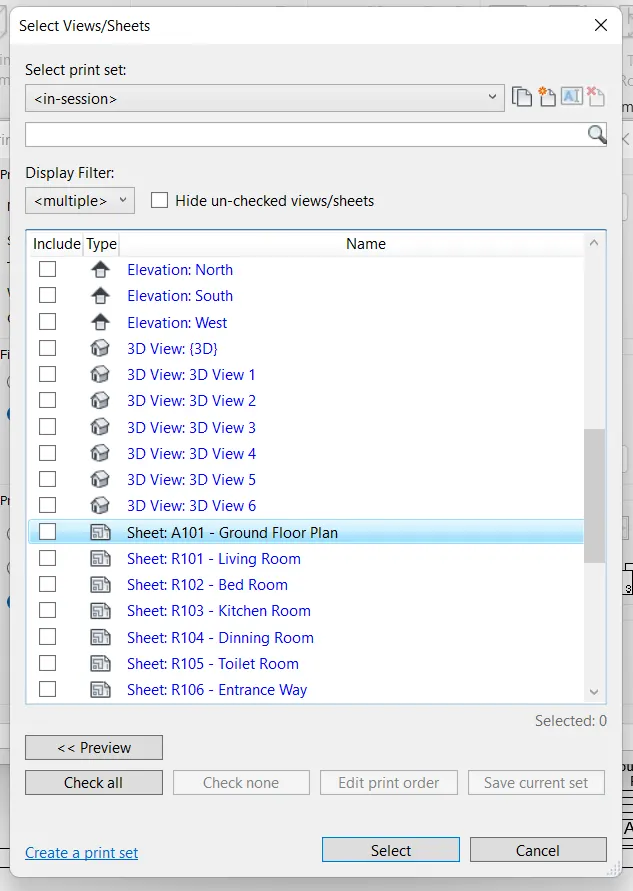
1. In the print range section, click on the selected views/sheet option
2. Select the sheet that we want to print
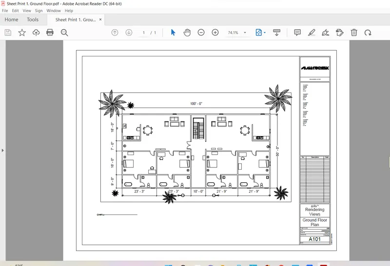
3. I'm selecting the Sheet A101 - Ground Floor Plan and click ok
Step 5:
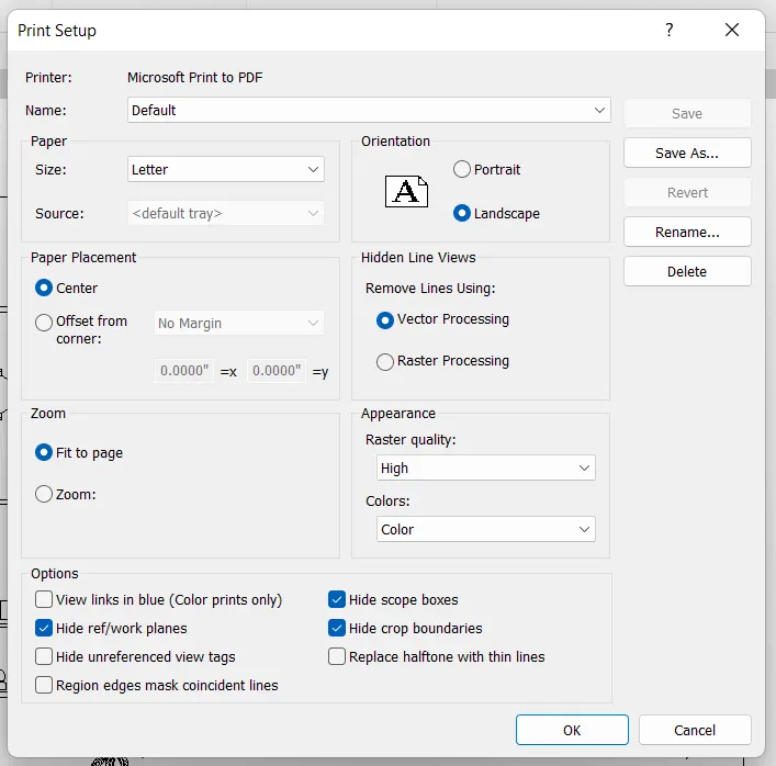
1. In the Setting sections, open the setup dialog box
2. Select the Paper size, orientation, and settings related to the paper sheet
3. After changing all the settings, click on ok to apply the changes
Step 6:
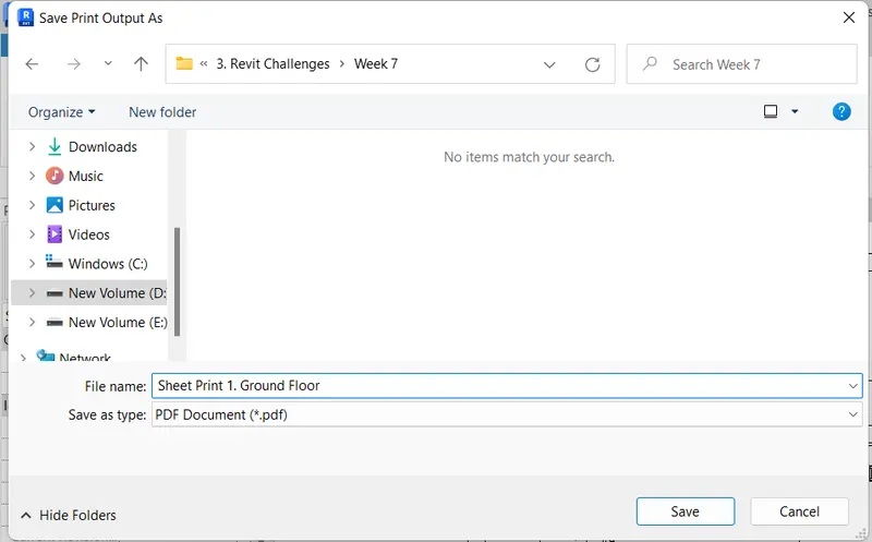
1. Click on ok and save it on the destinated folder
2. Save the PDF file of the sheet template with the specific name as shown in the figure below
3. Similarly we can print all sheet drawings using a print tool
RESULT:
The set of drawing sheets from the architectural model and structural model has been Printed into Microsoft Print PDF successfully