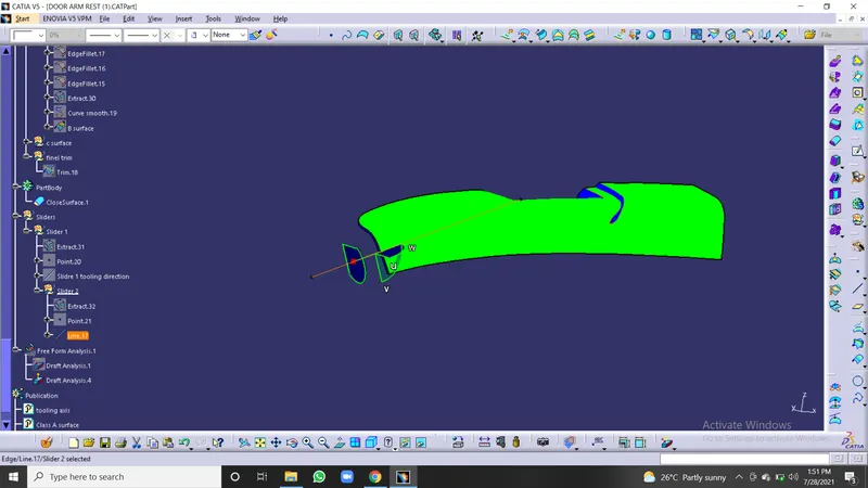
Door Arm Rest Week 8 Challenge
Tooling Axis-
- Check the Connectivity of class A Surface: these can be done by creating boundaries or by joining command if there are any gaps or openings they will be easily visualized.
-Visually analyse the best possible tooling axis.
-the clearance checking along all the axis on the plane with the model and constructing two lines contact with the walls, the line bisecting the two lines and passing through the point will be the tooling Axis.
For This, we use the positioned sketch to Create the tooling Axis
The intersection of the y Axis-
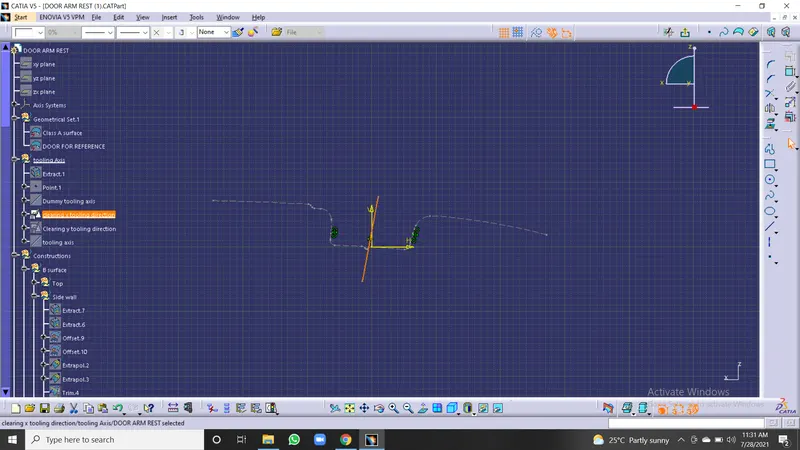
clearing tooling axis along y-direction-
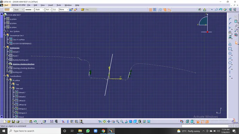
Using the intersection line, two lines created with the help of Two Sidewalls from the interaction created, a bisecting line passing between two lines will be the Direction clearing tooling axis.
The intersection of the x Axis-
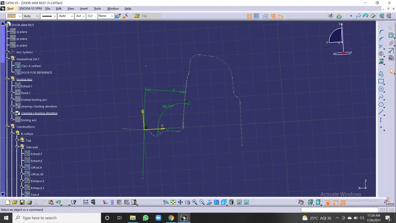
clearing tooling axis along X-direction-
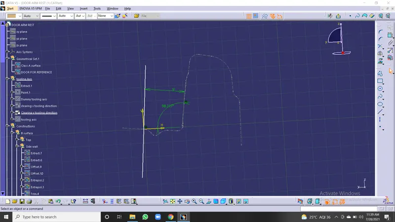
Using the interaction line, a line will be created along the wall. there is only one wall another line will be created at a certain angle this line is used for creating the main tooling axis.
Creating of main tooling Axis-
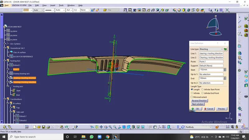
Using the tooling axis created along the y axis And X Axis these two lines and point are given as input for the bisecting line and that bisecting line is the Main tooling Axis.
Draft analysis on Class A surface-
Draft analysis compass is used to define the draft direction.
check whether the minimum draft of 3deg is assumed or not. the minimum draft of 3 deg is provided with the whole component changes into green colour.
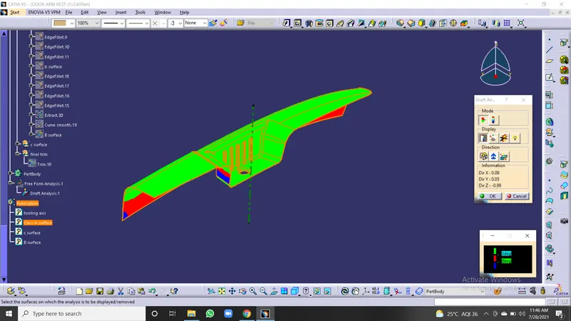
The publication is done to easily access the operation without searching in the tree structure -
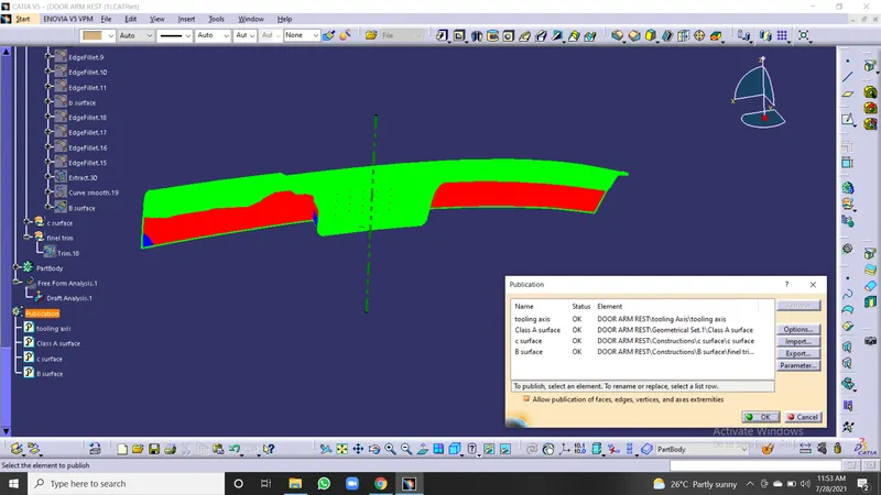
Class b surface is created by extracting the sides by using the extract command and the untrim them using the untrim command if that untrimmed surface is not interacting with the other required surface and then we can extrapolate the surface using the extrapolate command to the required side, and offset them to the given thickness of the model and trim them together and remove the unwanted surfaces.
the thickness of the model is 2.5mm
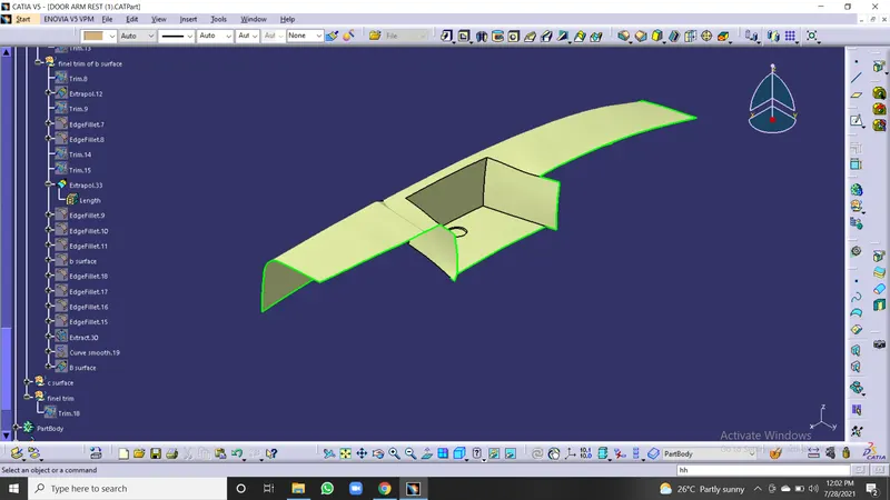
fillets should be given as per the given class using the edge fillet.
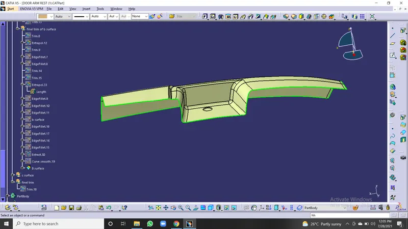
this is the final b surface.
C surface is created using the A surface by the sweep command. sweeping the boundaries of a surface along the tooling axis to the 3deg draft.
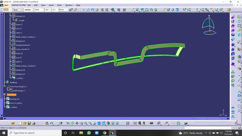
the connection between class a and class b is called the c surface.
by using the trim command the class a and class c is trimmed and connected together.
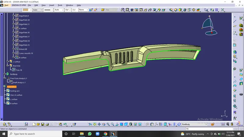
the final trim is done with b surface and the access surface will be removed this surface should ensure that there is no gap between the surfaces by using the boundary command if no boundary is formed then the output is correct.
the final trim is converted into the solid part using the closed surface option in the part design.
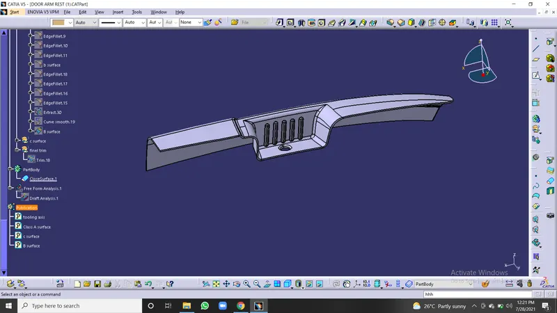
Draft analysis on the final model-
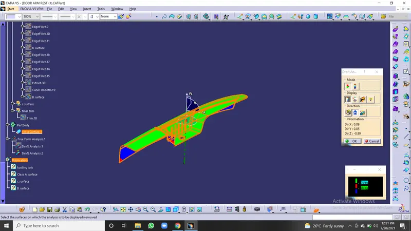
Front View-
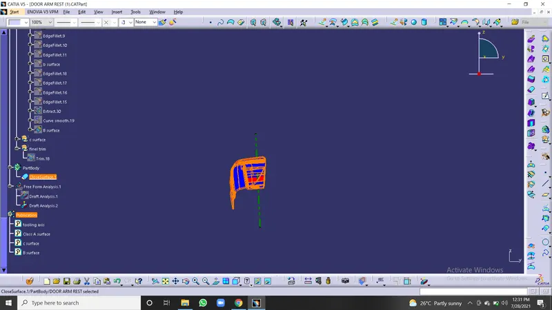
Side view-
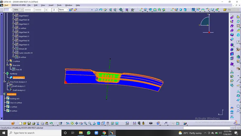
Top view-
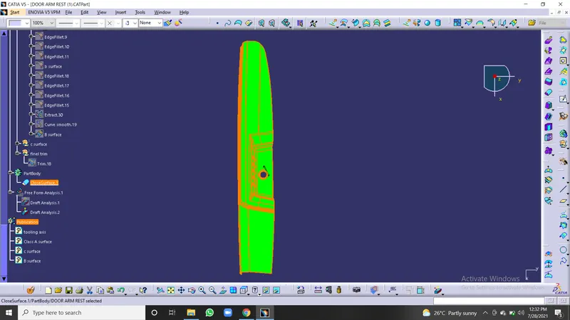
hear we have to ensure that it is clearing the draft analysis in all the sides with the main tooling direction if it is not clearing we have to create the slider tooling detection to clear the draft analysis.
Slider 1 tooling direction-
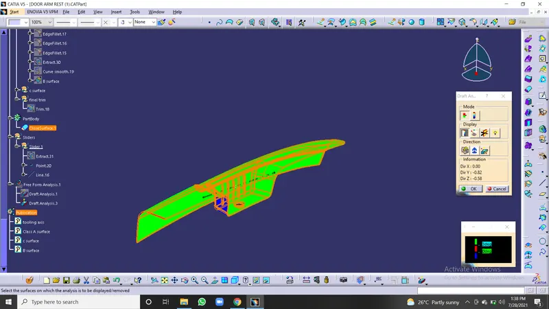
Slider 2 tooling direction with draft analysis-