Week -2
AIM:-
1. To Make a Simulink model of a Doorbell using a solenoid block.
Introduction:-
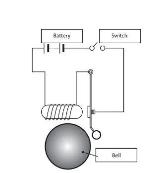
Doorbell-The Electric Doorbell is a device having Mechanical & Electrical Component produce sound by pressing the button. When the switch is pressed, the circuit is completed, which allows current from the battery to flow through the circuit, while passing the Solenoid it generates electromagnet in the desired space, which allows the plunger to move, due to which it hits the bell and produces sound.
Solenoid-
The solenoid is a type of Electromagnet, the purpose of which is to generate a controlled Magnetic field through a coil wound into a tightly packed helix. The coil can be arranged to produce a uniform magnetic field in a volume of space when an electric current is passed through it.
Procedure-
- Here in the simulation, we require to produce the sound in the doorbell when the switch is on.
- We need to use a solenoid in the setup to produce an electromagnet that moves the plunger and hits the bell to produce sound for 2sec and stop.
MODEL-
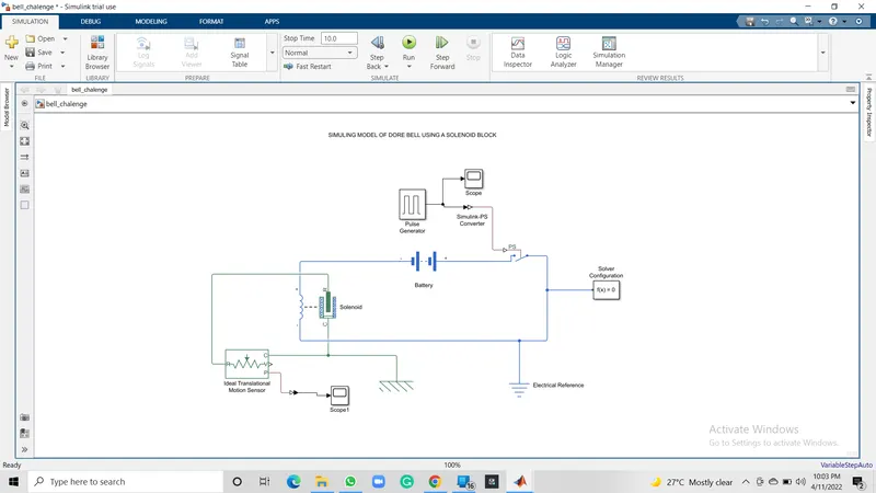
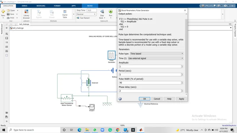
As per the requirement we need to move the plunger for 2second and stops which is possible by using the Pulse Generator, we need to configure the parameter in the pulse generator as per our need, like; Amplitude, Period, Pulse Width & Phase Delay. to get the desired pulses as output
- Simulink to Physical Signal converter is used.
- The battery is connected to provide the current to the circuit with a switch so that it will on/off on a particular signal.
- Solenoid is connected to the system to move the plunger, solenoid converts electric energy to mechanical energy by generating electromagnetism around the plunger, which ultimately moves the plunger in the desired direction.
- Solver is provided to understand the type of and solves as per that.
- To understand the motion in a mechanical translational network, we use an Ideal Transitional motion sensor, to understand the motion of the plunger, by configuring the sensor from the initial position of 0 to 4 cm.
- To get the output, we use Scope, bypassing the signal through PS-Simulink Converter
- All Circuits need to be grounded to maintain the potential difference, which is done by using Electrical reference & Mechanical Translational Reference.
INPUT-
OUTPUT-
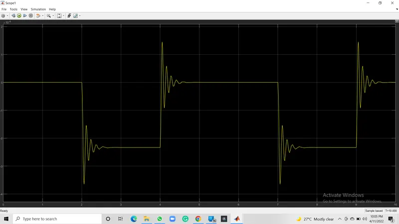
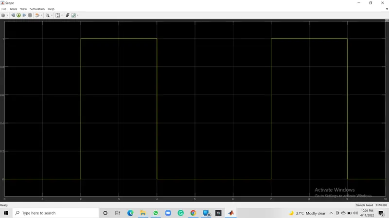
In this we use a solenoid to convert the electric energy into mechanical energy and made a Simulink model simulate the Doorbell, here we can conclude that the plunger is moving from its initial position of 5mm with a time delay of 2sec, this time delay happens while the plunger is suddenly disconnecting from the bell and moving away.
AIM-
By Using a Thermistor to sense the Temperature of a Heater & Turn On or Turn Off the Fan.
Introduction-
Thermistor- The term thermistor comes from “thermal” and “resistor”. A thermistor is a type of resistor whose resistance is reliant on temperature; it’s a resistance thermometer. They’re made from metallic oxide which is moulded into a bead, disk, or cylindrical shape and then enclosed with epoxy or glass.
Thermistors don’t work well with extreme temperatures, but they are perfectly suited for measuring the temperature at a certain point; they’re precise when they’re used within a limited temperature range i.e. within 50 °C of the target temperature; this range is dependent on the base resistance.
PROCEDURE-
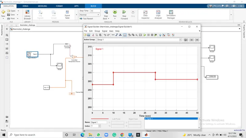
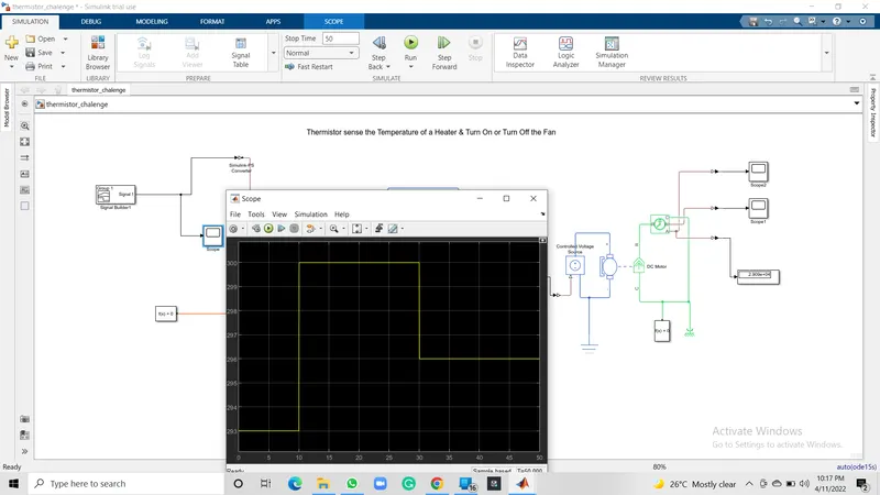
As per the given condition for temperature and time (20 °C from 0 to 10 seconds, 27 °C from 10 to 30 seconds, 23 °C from 30 to 50 seconds), These values are provided as input to the Signal Builder and configured as per our condition.
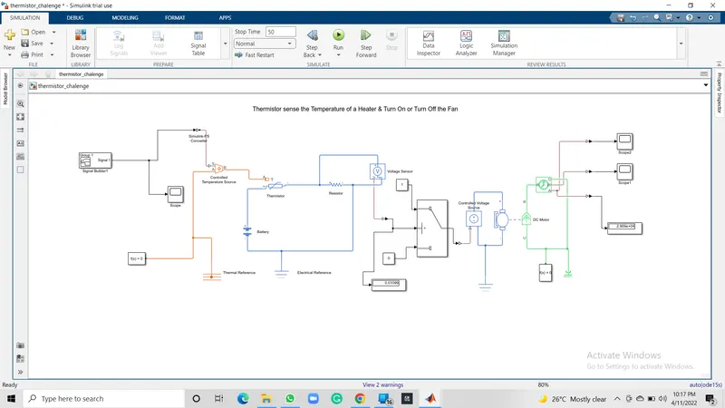
Passing the signals of Signal Builder(input) through Simulink-PS Converter to Thermister, we need to add a Controlled Temperature source in between, as Thermister won't understand the input as it is.
- The output of Controlled Temperature Source is used as input to Thermister and to maintain potential difference Thermal Reference is added to it.
- A controlled Temperature Source block represents an ideal source of thermal energy that is powerful enough to maintain a specified temperature difference across the source regardless of the heat flow consumed by the system.
- The battery is connected to run the circuit, a solver is also used to understand the type of system.
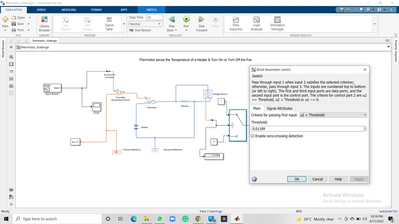
- A Voltage Sensor is used across the connected Resistor, to measure the voltage as a threshold value for the condition of our circuit.
- To fulfil our Fan conditions(ON if the temperature is above 25 °C, OFF otherwise) we add a Switch and provide the threshold value, this will work as an if-else loop, to give the condition as right or wrong we add constant blocks,
- If our condition is greater than the threshold value it will turn off the fan else turn off the fan.
- Scope and Display blocks are used to get the result as output.
MODEL-
INPUT-
THRESHOLD VALUE-
OUTPUT-
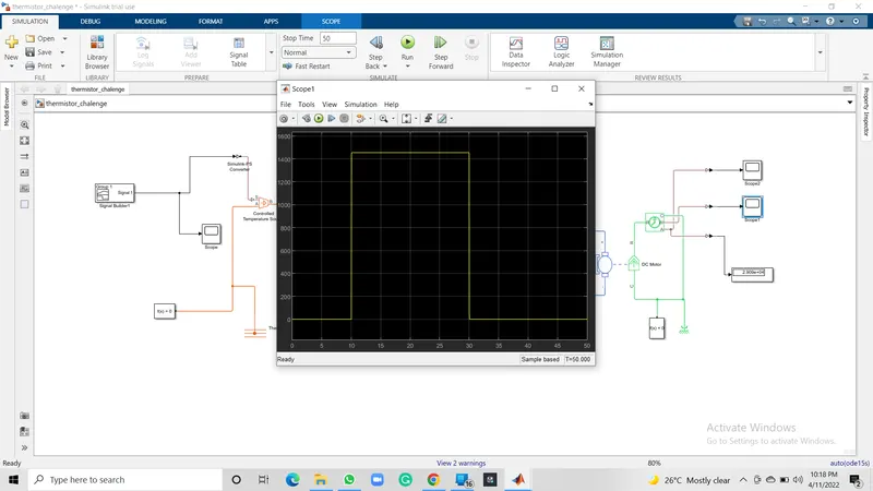
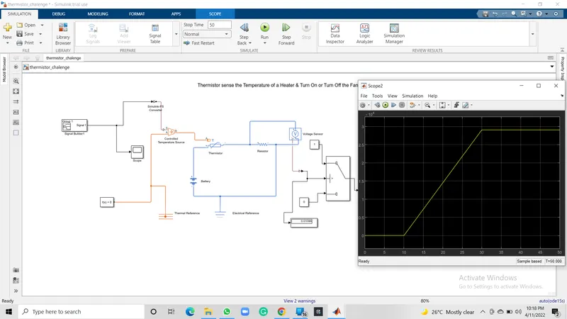
In the second model, we use Thermister to sense the temperature and according to our condition, we put the threshold value to the switch block to turn on and turn off the fan at a particular temperature.