Week 11 - Final project
Introduction-
10 Stages of Product life cycle of automotive Industry are
1. Concept sketch
2. Styling class A
3. Feasibility check
4. Concept validation
5. New Product Design
6. Product Development
7. Proto Build
8. Design Validation
9. Pilot Production
10. Mass production
New Product Development CAD: this is the stage where the major work of product design, by taking inputs from the concept sketch to validate the product will go to design using design software such as Nx, catia, solidworks, solid edge etc. IN this stage through design all the surfaces are divided into sub parts from the class A surface and Ensuring product should be workable. Making the 3D model and 2D drawings for development. Here product design is going to complete 100%.
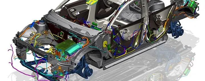
Example: Designing the car surface with the help of class A and clay model here designer going to detail producing the model from the point of manufacture, assembly etc ,
Aim-
Is to Design a Car door Plastic components are placed in the car door panel by following the design standards used in the Industries. The Reference Designs for the Mechanical design team of the Plastic components are drawn initially by the Class A surface defined by the Concept Sketch team as well as by the Styling Class A using Alios software and in reference to Class A, the Part Body with thickness is designed by the Designing Team.
Factors to consider before choosing a material for the component,
- they are Ease to manufacture.
- Cost-effectiveness.
- Material Physical and mechanical properties.
- Is of availability in the society.
- Suitability to the surrounding change of environment.
- Reliability.
- Easy to handle.
- Eco friendly
Types of Plastic-
Thermoset Plastic-
Thermoset type of plastics is the plastics that are non-usable once it is moulded to the required shape, if it is reheated to transform into a new plastic product is impossible and it becomes irregular in the form of shape and properties. Example - Bakelite which is used as a sausage handle which is black in colour, Trolley Wheels, Polyester, epoxy resin etc
Thermoplastic-
Thermoplastic is the type of plastic that is used and recycled to transform into a new product without affecting its properties. Thermo means temperature where the plastic is heated every time to change into a new product. Example - Low density and high-density Polyethylene types of plastic commonly known as grocery bags, nylon, PVC etc.
Advantages and Disadvantages of Thermoset type of Plastic,
Advantages-
- Is hard as concrete whereas Set (like concrete) is meant to say it is Rigid material.
- It has a higher melting point as compared to a thermoset.
- Is used in Handles of Sause pan, Epoxy is used as resin and Polyester for Clothing.
- Will not change its shape as per the change in the surrounding environment.
- Non-corrosive.
- Non-toxic while in use.
- Cost-effective.
- The thickness of the material can vary from minimum to maximum.
Disadvantages-
- It will not revert back to its original shape if it cannot be moulded to a new shape once it is heated beyond its melting temperature.
- They cannot be moulded to a very small thickness whereas used in grocery bags.
- Brittle material where it will break to high load.
- toxic when it is heated to melt into a paste.
Pros of Thermoplastic-
- The thermoplastic products are reverted back to new products with new shapes and the same material properties by melting beyond their melting point temperature.
- The thermoplastic material is with low melting point temperature compared to Thermoset type pf material.
- Low density and high-density types of plastic products are used for grocery, packaging plastic materials, containers, Nylon as ropes, and PVC for pipes.
- Fast processing
- No chemical reactions occur during application processing.
- Resists Humidity and other harsh environments.
Cons of Thermoplastic-
- Limited serve temperature performance.
- It tends to form weaker adhesive bonds.
The Following Methods are used to Produce Plastics-
Thermoset Type Plastic-
- In general, thermoset products are made through liquid moulding processes.
- The polymers and other agents are fed into tanks or barrels, where they are heated to a liquid state and mixed. Then the liquid polymers and other agents are injected into a mould cavity.
- As the material cools and hardens to the configuration of the cavity, it goes through a curing process where the polymers cross-link together.
- That process forms an irreversible chemical bond that prevents the risk of melting, softening, or warping when or if the finished product is subjected to high heat or corrosive environments. This makes thermosets perfect for high-heat applications and outdoor use.
- There are two primary liquid moulding processes used to produce thermoset plastics:
- Reaction Injection Molding.
- Resin Transfer moulding
Thermoplastic-
- Thermoplastic sheets are manufactured from raw materials, including polymer resins, colourants, and additives, depending on the specific formulation required.
- Raw materials are blended to exacting standards to ensure uniformity throughout the batch and consistency between batches.
- Once the raw materials are blended, they are heated, pressed through an extrusion die, and drawn into a sheet through a set of rollers. While the sheet is still warm, it passes through additional roller sets to reach the desired thickness and specified surface texture.
- As the sheet travels down the line, it cools and is cut to size. This process ensures dimensional stability and a uniform thermoplastic sheet.
- Thermoplastics are characterized by their pliability above a specific temperature, and ability to re-solidify upon cooling. This allows them to be easily shaped and moulded without changing the properties of the thermoplastic material.
Types of Thermoplastic-
Thermoplastic material is classified as-
- polypropylene
- polyethene
- polyvinylchloride
- polystyrene
- polyethene terephthalate
- polycarbonate
- Acrylonitrile butadiene styrene (ABS) is a thermoplastic used to
- manufacture-Sports equipment.
- Toys (for example LEGO® blocks).
- Various automobile parts
Polycarbonate is used to make
- CDs and DVDs
- Drinking bottles
- Food storage containers
- Eyeglass lenses
- Polyethene is probably the most common thermoplastic and is used to make
- Shampoo bottles
- Plastic grocery bags
- Bullet-proof vests
- Polypropylene is used to make
- Fibre for yarn and fabric
- Film for packaging or many other shapes
Types of Thermoset Plastic-
Thermoset type of Plastic, they are
- Epoxy resin.
- Polyester resin.
- Glass-reinforced type of plastic.
- Carbon fibre plastic.
- Melamine Formaldehyde.
- Silicones
- phenolic
- Alkyd
ABS-
ABS stands for Acrylonitrile Butadiene Styrene,
Acrylonitrile - This component contributes to ABS chemical resistance & heat stability
Butadiene- This component delivers toughness & impact strength to ABS polymer
Styrene- It provides rigidity & processability to ABS plastic.
Overall-
- High rigidity
- Good impact resistance, even at low temperatures
- Good insulating properties
- Good weldability
- Good abrasion and stain resistance
- High dimensional stability (Mechanically strong and stable over time)
- The high surface brightness and excellent surface aspect
Plastic Components used generally in Automobiles-
These engineering polymers are thermoplastics, and they have good chemical and temperature resistance; provide strength, toughness, and stiffness and resist wear and abrasion.
Parts in Automobile industries use Nylon as material are,
- Manifolds
- Fuel pipes
Nylon Clay hybrid (NCH) provides a barrier against vapour emission.
- Door
- tailgate handles
- Exterior mirrors
- Front-end grilles
- Fuel caps and lids
- Wheel covers and trim
Nylon fibres are exceptionally strong and elastic and stronger than polyester fibres. The fibres have excellent toughness, and abrasion resistance, and are easy to wash and to dye in a wide range of colours. The filament yarns provide a smooth, soft, and lightweight fabric of high resilience.
Filler-
Filler materials are particles added to resin or binders (Plastics, composites, concrete) that can improve specific properties, make the product cheaper, or a mixture of both. The two largest segments for filler material used are elastomers and plastics.
Fillers with properties-
- Calcium carbonate (CaCO3): It. brings for final plastic products brighter and glossier surface.
- Kaolin: Is mainly used in plastics for its anti-blocking characteristics as well as an infrared absorber in laser marking. It increases impact strength and heat resistance.
- Wollastonite (CaSiO3): This filler can improve moisture content, wear resistance, thermal stability, and high dielectric strength.
- Glass: Glass fibres are used to increase the mechanical properties of the thermoplastic or thermoset such as flexural modulus and tensile strength.
Edit
Additives-
A substance added to something in small quantities to improve or preserve it.
The most common polymer additives are stabilizers, plasticizers, lubricants and flame retardants.
- Stabilizers are added to prolong the useful life of a polymer formulation by protecting it from thermal and light-assisted oxidation.
- Plasticizers: Plasticizers are additives used in the production of plastics to reduce the attraction between polymer chains, thereby increasing the flexibility and durability of the resulting plastic. The most common Plasticizers are phthalate esters, which are used primarily in the manufacturing of products made from PVC, including shower curtains, upholstery, flooring, and food containers.
- Lubricants are the substances, which work between surfaces in relative motion to prevent friction and wear
- Flame retardants are chemicals that are applied to materials to prevent the start or slow the growth of fire.
Materials Used in Automobile with respect to the Components-
The 10 Automotive interior components and the materials used are,
- Truck trim - Steel.
- trunk - Steel
- door panels - Fibre
- Instrument panel - Acrylonitrile-butadiene-styrene (ABS), ABS/polycarbonate alloys, polycarbonates, polypropylene, modified polyphenylene ether (PPE) and SMA (styrene-maleic anhydride) resins
- Glove box - Stainless steel, Carbon fibre, polycarbonates, polypropylene
- center console - Carbon fibre
- Headliner - tricot knit fabric
- Ac register - Polyurethane and phenolic insulation panels.
- SOS switch - Bakelite and Ebonite
- Control knob - Stainless steel
The 10 Automotive Exterior components and the materials used are,
- Spoilers - Is made from ABS plastic, which is mixed with granular fillers to make the spoiler stiffer.
- Automotive lighting - Acrylonitrile-butadiene-styrene (ABS), polycarbonates, polypropylene.
- Bumper - Steel, fiberglass composite, plastic or aluminium
- Wheel arch - fibrous layer comprising of thermoplastic bicomponent filaments
- A pillar - Steel, Aluminium.
- Cover wheel bright work - High-grade sheepskin fabric.
- Silencer - Stainless Steel
- Protector - Stainless steel.
- Wheel trim - zinc coated steel with a hardness of 40 HRC
- Wiper - Blade of Aluminium and attached with rubber.
There are 5 types of thermoplastic molding, they are
- Extrusion moulding: The extrusion moulding, hot melted plastic is pressed through a shaped hole to create a lengthy shaped plastic part. This customizable shape that the liquid plastic gets pressed through is called a die. This die is custom made for the particular outcome that is desired. It is almost like pressing dough through a press to make shaped cookies. The other forms of plastic moulding also use extrusion so get the raw liquid into the moulds, the difference here is that other methods use the moulds to make the desired shape and here the extrusion itself is making the shape with the use of the die’s shape.
- Compression molding: This method involves the raw liquid plastic being poured into a heated mould and then being compressed together to form the desired shape. The high temperature of the entire process ensures good strength in the final product. The process is finished off by cooling the liquid plastic so that it keeps its form before being trimmed and removed from the mould.
- Blow modling: With blow moulding, the custom plastic parts come out hollow and thin walled. This method is ideal for when the plastic part must have uniform wall thickness. This is very similar to the process of glass blowing. The machine heats up the raw plastic until it becomes liquid and then injects air into it like a balloon. The plastic is blown into a shaped mould and as it gets bigger it presses against the mould walls and it starts to take its shape. After the liquid balloon fills the mould it is cooled to keep its shape. The process is very fast and can produce up to 1400 pieces in a 12-hour work day.
Injection Moulding: Injection Moulding is fairly similar to extrusion moulding. The difference here is that with injection moulding the melted plastic is injected directly into a custom mould. The injection is under high pressure so that the mould is filled, and a solid part is made. As with the other methods, after the mould is filled, the plastic is cooled as to keep its new shape and then the mould is opened.
Rotational molding: This method involves the resin or liquid being placed inside the mould and then being rotated at high speeds. The liquid then evenly covers the entire surface of the mould to create a hollowed part with all the walls evenly thick. After the mould is cooled and the liquid plastic has taken its new form it is then taken out of the mould.
Class A surface-
Class A surface refers to those surfaces which are visibel and abide to the physical meaning, in a product. This classification is primarily used in the automotive and increasingly in consumer goods.
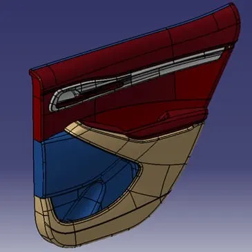
Car Door panel-
OBJECTIVES
- Create a sketch by using Positioned sketch
- All the should be sketches should be Iso-Constrained
- Ensured Proper Tree Structure
- Geometrical sets should having a proper name based on the sketches present inside of it
- Create thickened part using master section for reference
- Create the mounting features as per design guidelines in the industry and with master sections
- Creating of Draft analysis & Tooling analysis
- Creation of parting lines and check tooling feasibility
INPUT OF CLASS A SURFACE
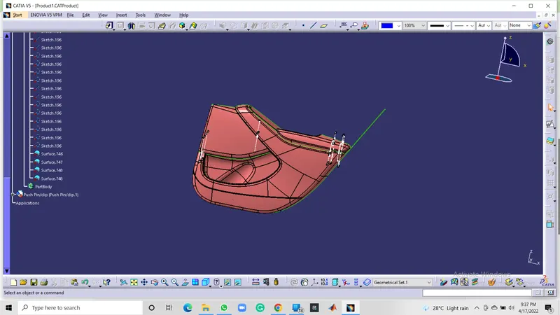
Since the input class A surface is containing four different parts(class A). So class b and c for all the surface has been created in separate catpart. Also performing draft analysis and tooling axis separately. finally all the surface have assembled together in one catproduct.
UPPER SUBSTRACT-
INPUT-
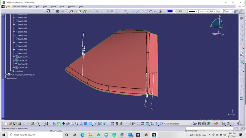
Tooling Axis-
- Check the Connectivity of class A Surface: these can be done by creating boundaries or by joining command if there are any gaps or openings they will be easily visualized.
-Visually analyse the best possible tooling axis.
-the clearance checking along all the axis on the plane with the model and constructing two lines in contact with the walls, the line bisecting the two lines and passing through the point will be the tooling Axis.
but for this cat part, the bisecting method is not required because every part of the cat can be cleared throw the Z direction only easily.
The tooling axis is nothing but the direction in which the core and cavity open and close. The design engineer works are to analyse the Class-A surface and find out the best possible tooling direction keeping in mind all the draft angle is with respect to the tooling axis so that the component can be easily ejected from the moulds.
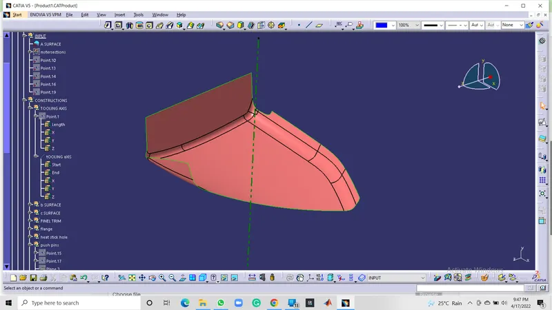
Class A surface-
In automotive design, a class A surface is any of a set of freeform surfaces of high efficiency and quality. Although strictly, it is nothing more than saying the surfaces have curvature and tangency alignment – to ideal aesthetical reflection quality, many people interpret class A surfaces to have G2 (or even G3) curvature continuity to one another. Class A surfacing is done using computer-aided industrial design applications. Class A surface modellers are also called "digital sculptors" in the industry. Industrial designers develop their design styling through the A-Surface, the physical surface the end-user can feel, touch, see etc. and the class A surface is created in the software called ALIAS.
Draft Analysis on Class A surface-
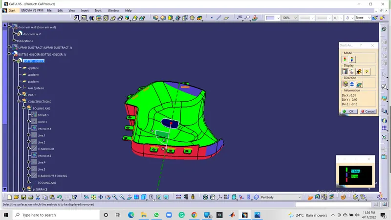
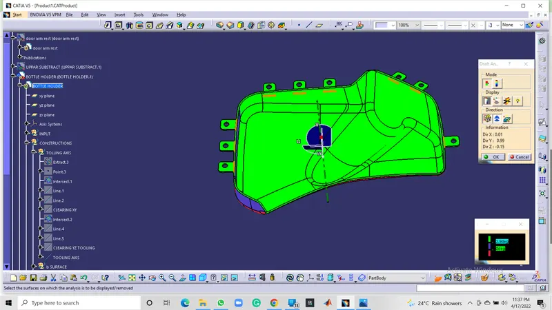
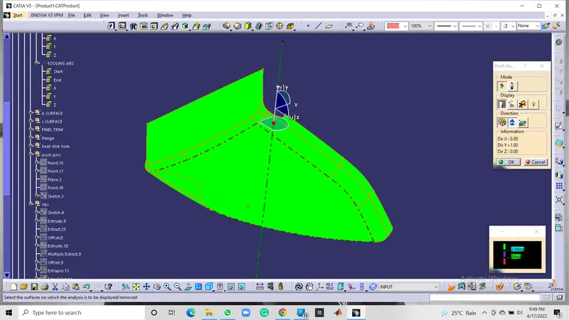
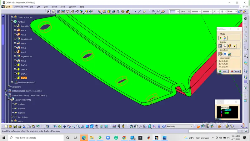
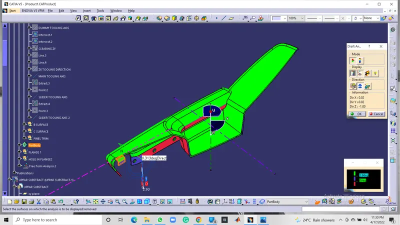
A draft analysis compass is used to define the draft direction.
check whether the minimum draft of 3deg is assumed or not. the minimum draft of 3 deg is provided with the whole component changing
Class B Surface Creation-
Represent internal and/or functional surfaces. This cluster exemplary includes derived surfaces created by offset operations from class A surfaces to define the thickness of the material (2.5mm). In this file, it is important to link class B surfaces geometrically to enable an adaptation to class A surfaces automatically in case of styling change.
After creating the tooling axis, a B surface is to be created which is nothing but the surface parallel to the A surface. B surface contains all the fillets and the edges which the A surface contains.
Updated class-B surface-
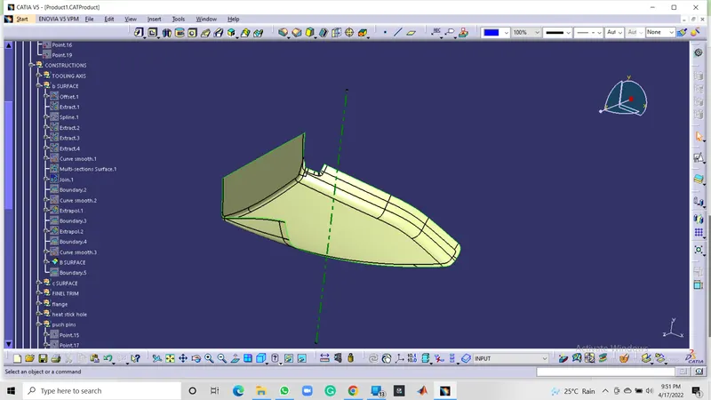
Class C Surface Creation-
Class C Surface is swept along the boundary of Class A at an angle perpendicular to the CLASS A surface with respect to the tooling axis direction with a draft angle of 3 degrees.
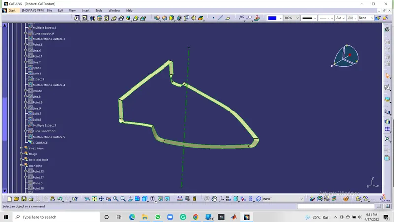
Joining CLASS A, B and C Surfaces to get Closed Surfaces-
After finishing all the 3 surfaces, join the class A and class C surfaces together using the Join command. Now, the joined surfaces are then trimmed with a class B surface to form a closed surface.
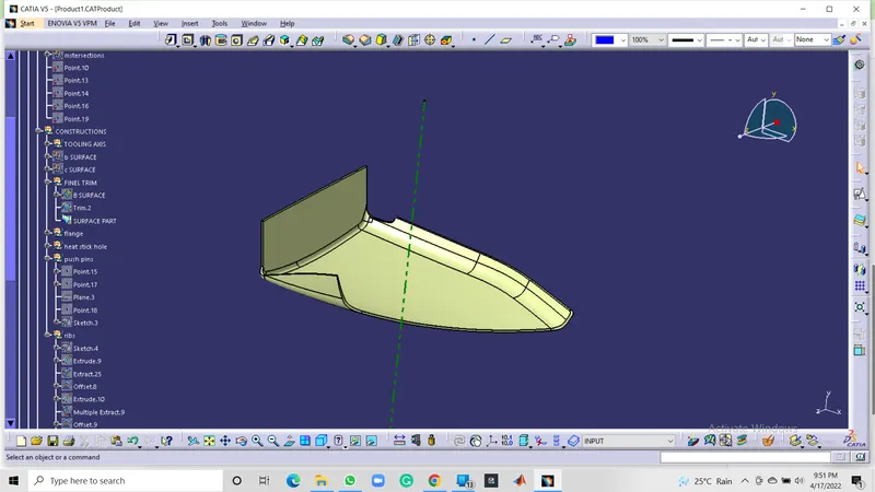
Making of the solid part using the class surface command-
after the completion of joining the class A, B, C surfaces ensure that the surface has no gaps between then using the boundary command if it did not form the boundary then the surface is closed switch to the part design and insert the new part body and use the close surface command to get the solid part.
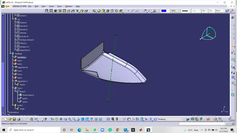
BOTTEL HOLDER-
INPUT-
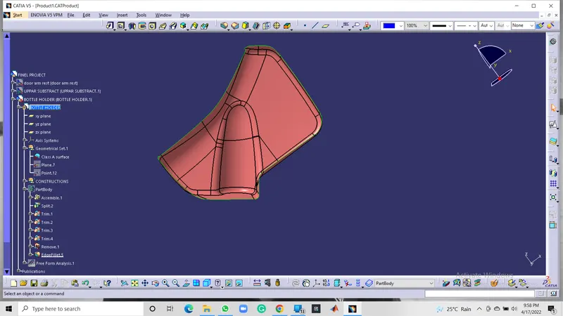
Tooling Axis-
- Check the Connectivity of class A Surface: these can be done by creating boundaries or by joining command if there are any gaps or openings they will be easily visualized.
-Visually analyse the best possible tooling axis.
-the clearance checking along all the axis on the plane with the model and constructing two lines in contact with the walls, the line bisecting the two lines and passing through the point will be the tooling Axis.
but for this cat part, the bisecting method is not required because every part of the cat can be cleared throw the Z direction only easily.
The tooling axis is nothing but the direction in which the core and cavity open and close. The design engineer works are to analyse the Class-A surface and find out the best possible tooling direction keeping in mind all the draft angle is with respect to the tooling axis so that the component can be easily ejected from the moulds.
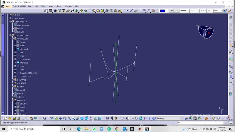
Class A surface-
In automotive design, a class A surface is any of a set of freeform surfaces of high efficiency and quality. Although strictly, it is nothing more than saying the surfaces have curvature and tangency alignment – to ideal aesthetical reflection quality, many people interpret class A surfaces to have G2 (or even G3) curvature continuity to one another. Class A surfacing is done using computer-aided industrial design applications. Class A surface modellers are also called "digital sculptors" in the industry. Industrial designers develop their design styling through the A-Surface, the physical surface the end-user can feel, touch, see etc. and the class A surface is created in the software called ALIAS.
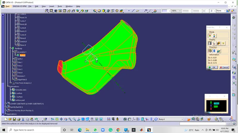
Draft Analysis on Class A surface-
A draft analysis compass is used to define the draft direction.
check whether the minimum draft of 3deg is assumed or not. the minimum draft of 3 deg is provided with the whole component changing
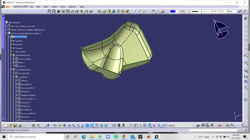
Class B Surface Creation-
Represent internal and/or functional surfaces. This cluster exemplary includes derived surfaces created by offset operations from class A surfaces to define the thickness of the material (2.5mm). In this file, it is important to link class B surfaces geometrically to enable an adaptation to class A surfaces automatically in case of styling change.
After creating the tooling axis, a B surface is to be created which is nothing but the surface parallel to the A surface. B surface contains all the fillets and the edges which the A surface contains.
Updated class-B surface-
Class C Surface Creation-
Class C Surface is swept along the boundary of Class A at an angle perpendicular to the CLASS A surface with respect to the tooling axis direction with a draft angle of 3 degrees.
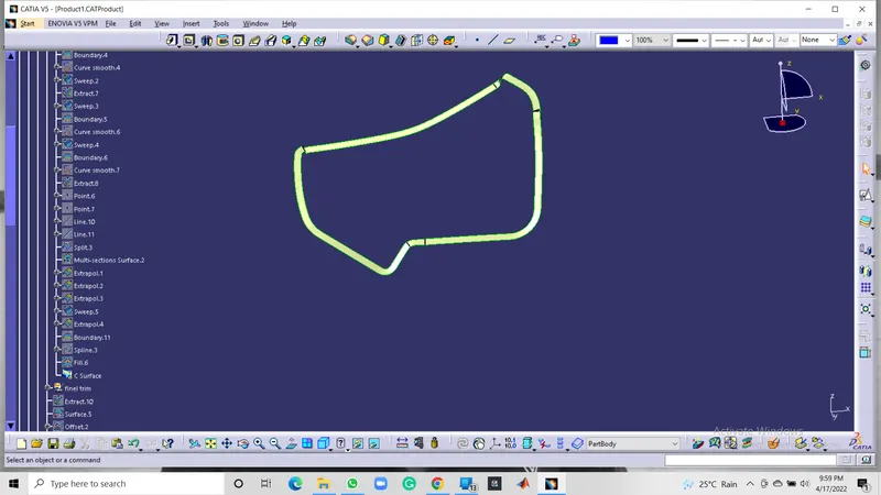
Joining CLASS A, B and C Surfaces to get Closed Surfaces-
After finishing all the 3 surfaces, join the class A and class C surfaces together using the Join command. Now, the joined surfaces are then trimmed with a class B surface to form a closed surface.
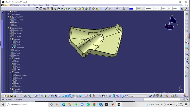
Making of the solid part using the class surface command-
after the completion of joining the class A, B, C surfaces ensure that the surface has no gaps between then using the boundary command if it did not form the boundary then the surface is closed switch to the part design and insert the new part body and use the close surface command to get the solid part.
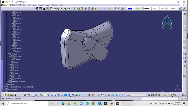
ARM REST-
INPUT-
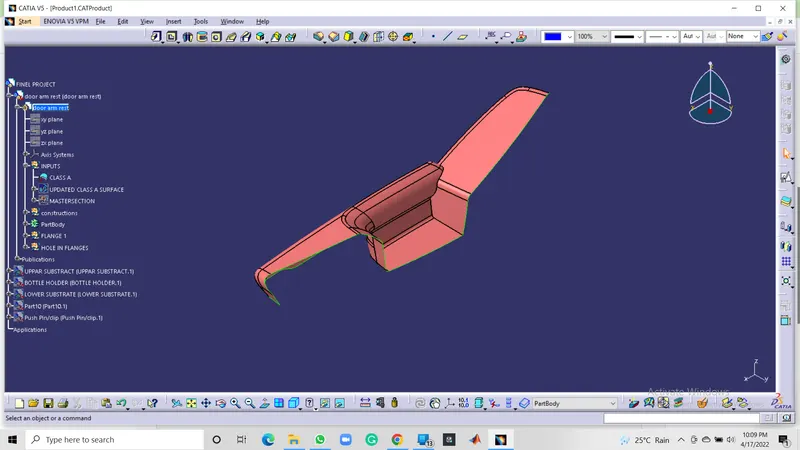
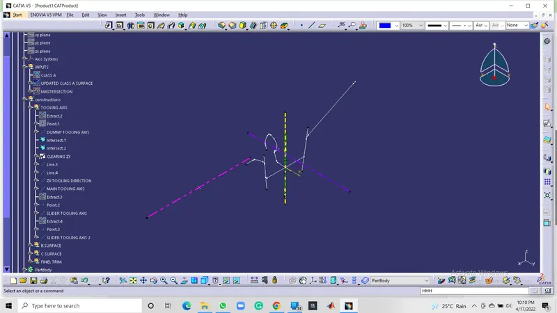
Tooling Axis-
- Check the Connectivity of class A Surface: these can be done by creating boundaries or by joining command if there are any gaps or openings they will be easily visualized.
-Visually analyse the best possible tooling axis.
-the clearance checking along all the axis on the plane with the model and constructing two lines in contact with the walls, the line bisecting the two lines and passing through the point will be the tooling Axis.
but for this cat part, the bisecting method is not required because every part of the cat can be cleared throw the Z direction only easily.
The tooling axis is nothing but the direction in which the core and cavity open and close. The design engineer works are to analyse the Class-A surface and find out the best possible tooling direction keeping in mind all the draft angle is with respect to the tooling axis so that the component can be easily ejected from the moulds.
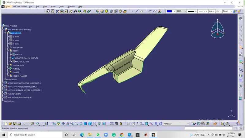
Class A surface-
In automotive design, a class A surface is any of a set of freeform surfaces of high efficiency and quality. Although strictly, it is nothing more than saying the surfaces have curvature and tangency alignment – to ideal aesthetical reflection quality, many people interpret class A surfaces to have G2 (or even G3) curvature continuity to one another. Class A surfacing is done using computer-aided industrial design applications. Class A surface modellers are also called "digital sculptors" in the industry. Industrial designers develop their design styling through the A-Surface, the physical surface the end-user can feel, touch, see etc. and the class A surface is created in the software called ALIAS.
UPDATED CLASS A
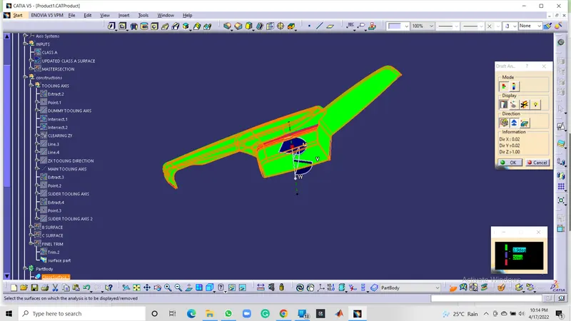
Draft Analysis on Class A surface-
A draft analysis compass is used to define the draft direction.
check whether the minimum draft of 3deg is assumed or not. the minimum draft of 3 deg is provided with the whole component changing
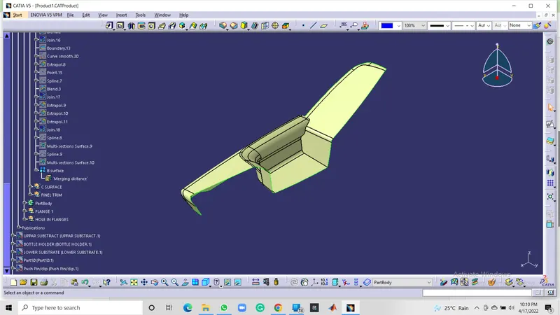
Class B Surface Creation-
Represent internal and/or functional surfaces. This cluster exemplary includes derived surfaces created by offset operations from class A surfaces to define the thickness of the material (2.5mm). In this file, it is important to link class B surfaces geometrically to enable an adaptation to class A surfaces automatically in case of styling change.
After creating the tooling axis, a B surface is to be created which is nothing but the surface parallel to the A surface. B surface contains all the fillets and the edges which the A surface contains.
Updated class-B surface-
Class C Surface Creation-
Class C Surface is swept along the boundary of Class A at an angle perpendicular to the CLASS A surface with respect to the tooling axis direction with a draft angle of 3 degrees.
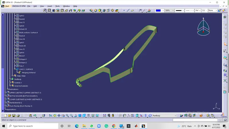
Joining CLASS A, B and C Surfaces to get Closed Surfaces-
After finishing all the 3 surfaces, join the class A and class C surfaces together using the Join command. Now, the joined surfaces are then trimmed with a class B surface to form a closed surface.
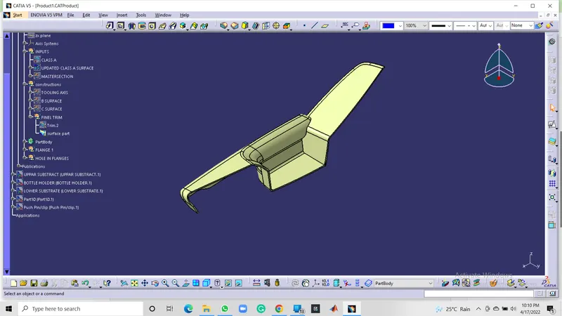
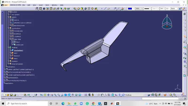
Making of the solid part using the class surface command-
after the completion of joining the class A, B, C surfaces ensure that the surface has no gaps between then using the boundary command if it did not form the boundary then the surface is closed switch to the part design and insert the new part body and use the close surface command to get the solid part.
LOWER SUBSTRACT
INPUT-
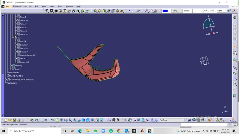
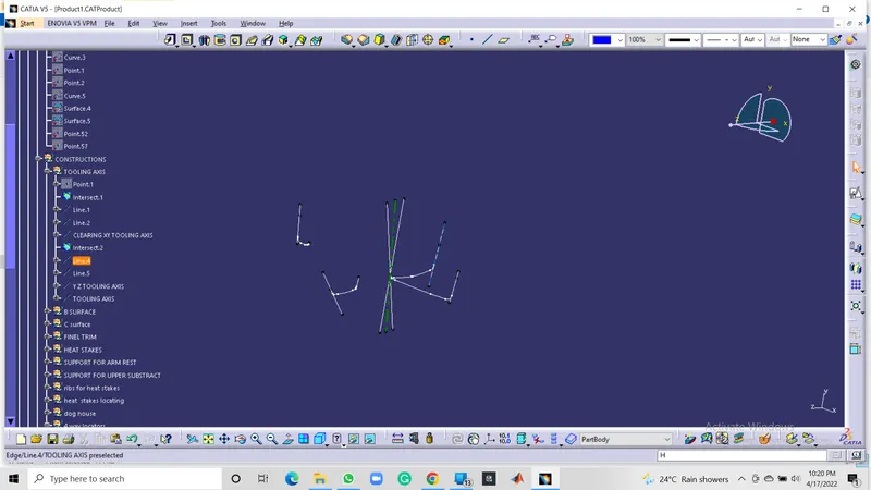
Tooling Axis-
- Check the Connectivity of class A Surface: these can be done by creating boundaries or by joining command if there are any gaps or openings they will be easily visualized.
-Visually analyse the best possible tooling axis.
-the clearance checking along all the axis on the plane with the model and constructing two lines in contact with the walls, the line bisecting the two lines and passing through the point will be the tooling Axis.
but for this cat part, the bisecting method is not required because every part of the cat can be cleared throw the Z direction only easily.
The tooling axis is nothing but the direction in which the core and cavity open and close. The design engineer works are to analyse the Class-A surface and find out the best possible tooling direction keeping in mind all the draft angle is with respect to the tooling axis so that the component can be easily ejected from the moulds.
Class A surface-
In automotive design, a class A surface is any of a set of freeform surfaces of high efficiency and quality. Although strictly, it is nothing more than saying the surfaces have curvature and tangency alignment – to ideal aesthetical reflection quality, many people interpret class A surfaces to have G2 (or even G3) curvature continuity to one another. Class A surfacing is done using computer-aided industrial design applications. Class A surface modellers are also called "digital sculptors" in the industry. Industrial designers develop their design styling through the A-Surface, the physical surface the end-user can feel, touch, see etc. and the class A surface is created in the software called ALIAS.
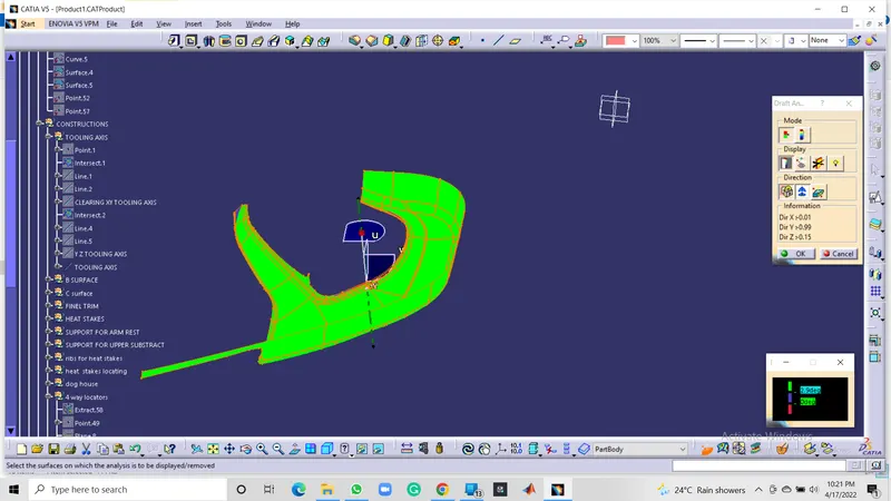
Draft Analysis on Class A surface-
A draft analysis compass is used to define the draft direction.
check whether the minimum draft of 3deg is assumed or not. the minimum draft of 3 deg is provided with the whole component changing
Class B Surface Creation-
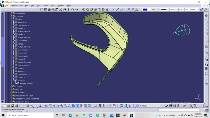
Represent internal and/or functional surfaces. This cluster exemplary includes derived surfaces created by offset operations from class A surfaces to define the thickness of the material (2.5mm). In this file, it is important to link class B surfaces geometrically to enable an adaptation to class A surfaces automatically in case of styling change.
After creating the tooling axis, a B surface is to be created which is nothing but the surface parallel to the A surface. B surface contains all the fillets and the edges which the A surface contains.
Updated class-B surface-
Class C Surface Creation-
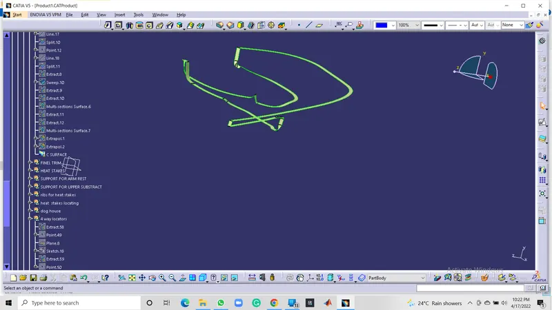
Class C Surface is swept along the boundary of Class A at an angle perpendicular to the CLASS A surface with respect to the tooling axis direction with a draft angle of 3 degrees.
Joining CLASS A, B and C Surfaces to get Closed Surfaces-
After finishing all the 3 surfaces, join the class A and class C surfaces together using the Join command. Now, the joined surfaces are then trimmed with a class B surface to form a closed surface.
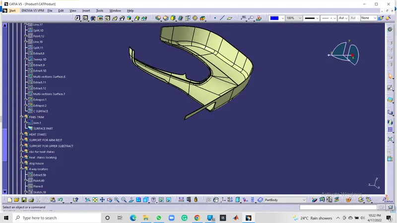
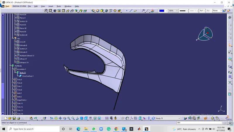
Making of the solid part using the class surface command-
after the completion of joining the class A, B, C surfaces ensure that the surface has no gaps between then using the boundary command if it did not form the boundary then the surface is closed switch to the part design and insert the new part body and use the close surface command to get the solid part.
FINEL OUTPUT WITH ENGINEERING FEATURES
OUTPUT
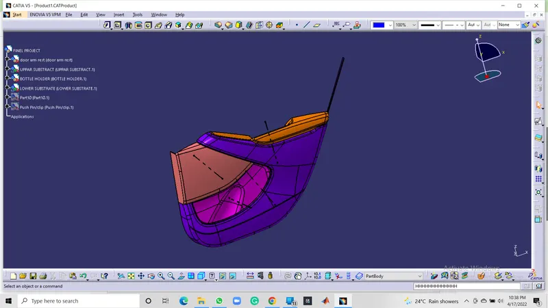
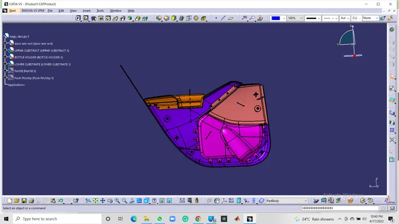
CREATION OF B SIDE FEATURES
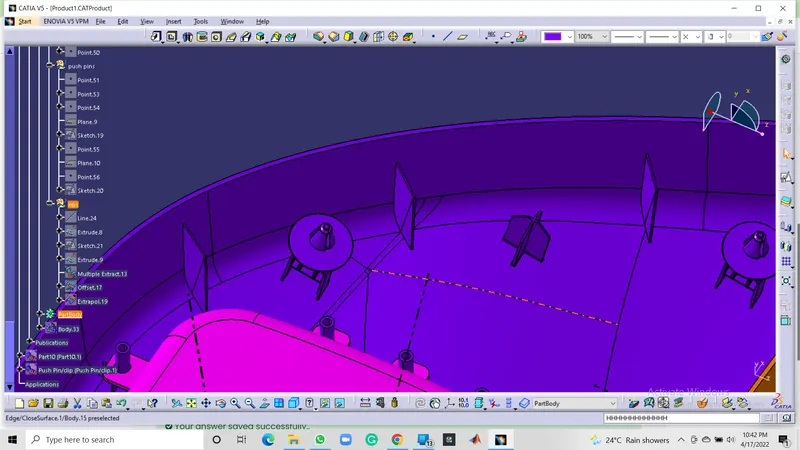
Creation of Ribs and Dog house And 4-way locators And Heat stakes-
4-way locators mean you prevent movement at 2 axes (+X, -X, +Y and -Y) on the plane. Generally, you have a cylindrical pin on the fixture and a circular hole at the workpiece part.
In any kind of assembly before fixing the part to the mating part we need to fix the position of the part with respect to the mating part. In these cases, we need to follow some engineering principles. In this project, we are going to follow the 3-2-1 Principle. Any Part which has to be fixed during the welding or machining process has to be fixed is having 12 degrees of freedom.
Translation Movement along X-Axis
Translation Movement along Y-Axis
Translation Movement along Z-Axis
Rotational Movement along X-Axis
Rotational Movement along Y-Axis
Rotational Movement along Z-Axis
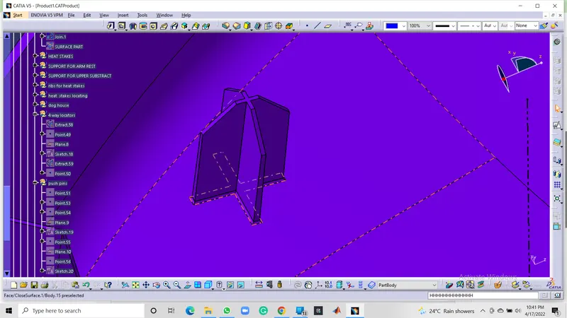
Dog House :
Create the dog house as per the design rules and give the required draft angle.
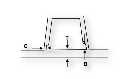
Doghouse wall thickness at the intersection of the part wall ( C ) should be 40% or less than the main wall stock ( T ).
The height of ( B ) should be between 3.0 – 6.0 mm
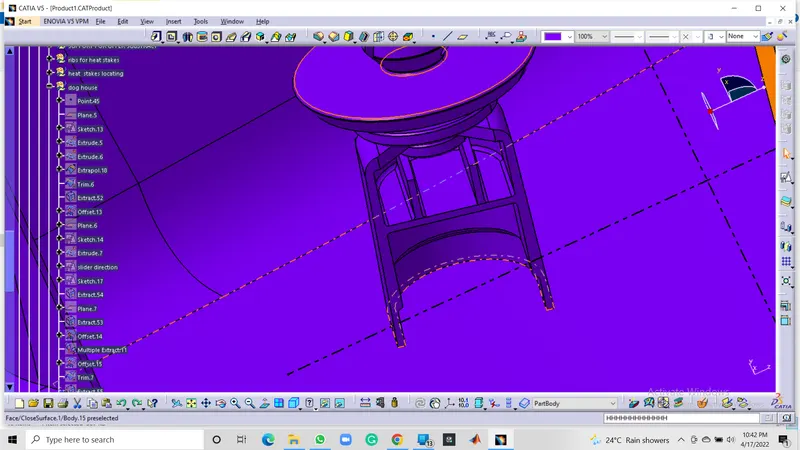
DOg house with 4way locator-
Ribs-
Rib design-
Ribs are used to strengthen the walls of the mould without increasing the overall wall thickness.it is an economical way to increase the stiffness of the component.
they help in-
Locating and arresting components of an assembly
providing alignment in mating parts
acting as stops or guides for mechanisms
ex- headlight
design rules to follow while cretin the ribs-
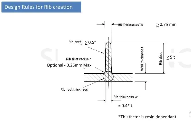
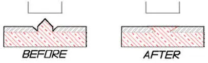
Heat Staking-
Heat Staking is a pulsed-heat process to join two or more parts out of which one at least is made of plastic. The process is to deform the plastic material using heat and force at a set process time. The bond is made by partially de-forming the plastic part in order to fix the other.
Heat Staking makes it easy to bond metal to plastic and is commonly used in high volumes/low-cost applications such as automotive, IT and consumer appliances.
In the Manufacturing Of thermoplastic components, it is often necessary to join the thermoplastic to a part of dissimilar material, whether it can be a metal, dissimilar material or other material. Thermal staking is an assembly method that uses the controlled melting and reforming of a plastic stud or boss to capture or lock another plastic or a metal component of an assembly in place. The plastic studs protrude through the holes in a component to be locked in a place. the heated thermal tip contacts the top of the stud, which melts and fills the volume of the tip cavity to produce the head, locking the component in a place. The progressive melting of the plastic under continuous pressure forms the head. When Staking, the right combination of heat and pressure for the applications is critical.
Advantages of Heat Stakes-
- Similar and dissimilar materials may be joined: metal to metal, plastic to plastic, metal to plastic.
- Accurate control operating within a small process window.
- Local heating results in no damage to surrounding materials.
- Processing of glass-filled materials.
- No mechanical vibration.
- Many heat-stake shapes are possible through custom-designed tools.
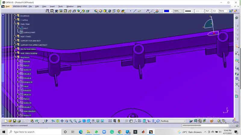
DRAFT ANALYSIS-
LOWER SUBSTRACT
DRAFT ANALYSIS FOR HEAT STAKE
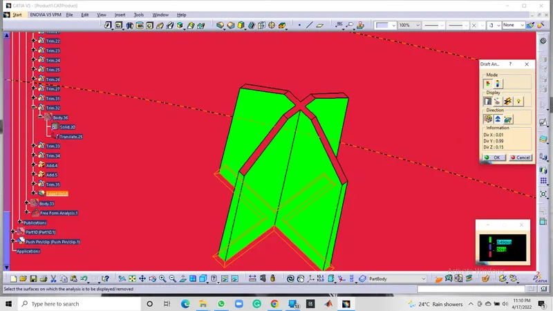
DRAFT ANALYSIS FOR DOG HOUSE AND PUSH PIN-
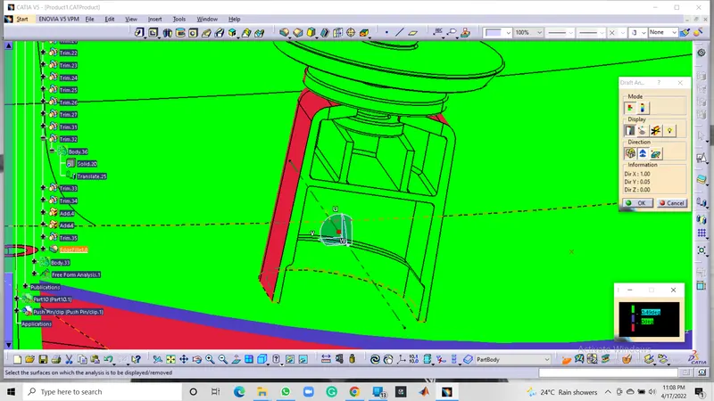
DRAFTA ANALYSIS ON LOWER SUBSTRACR-
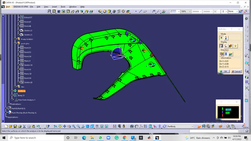
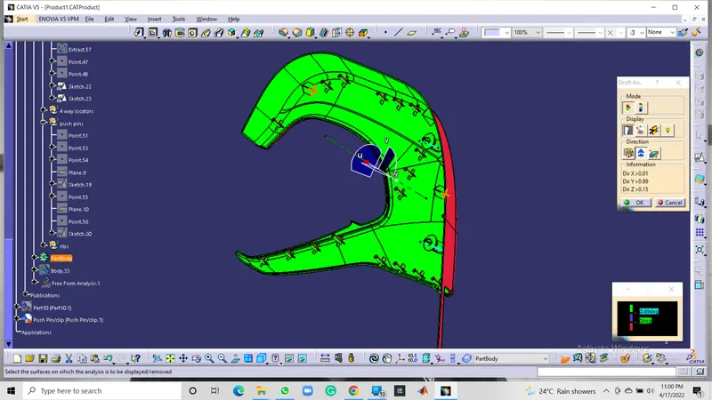
DRAFT ANALYSIS ON UPPER SUBSTRACT
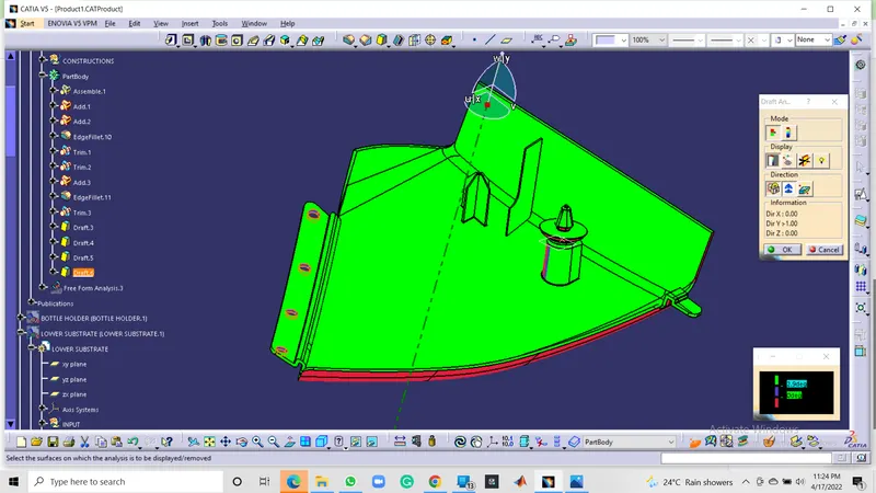
DRAFT ANALYSIS FOR ARM REST-
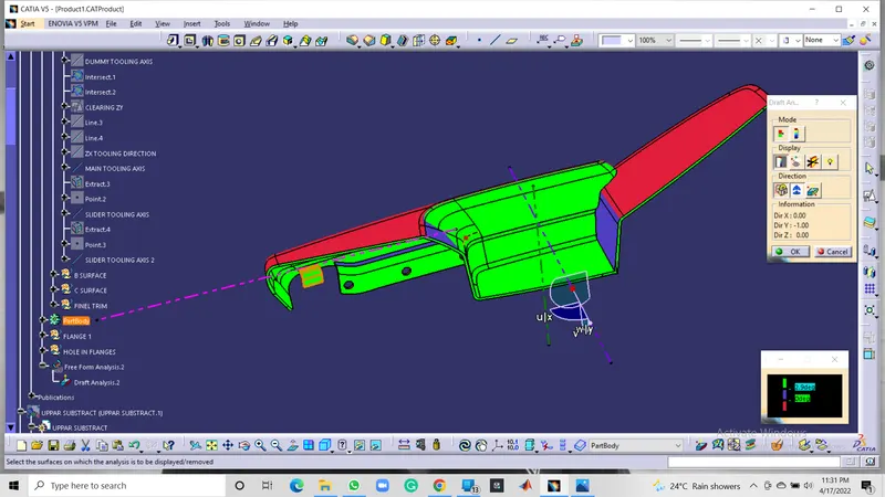
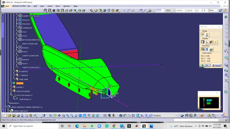
DRAFT ANALYSIS FOR BOTTEL HOLDER-