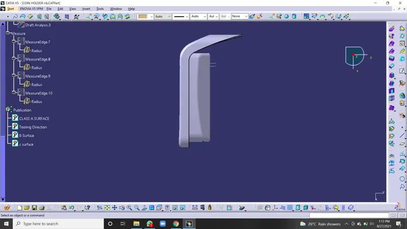
Week 9 - Attachment Feature Creation - Challenge 1
Tooling Axis-
- Check the Connectivity of class A Surface: these can be done by creating boundaries or by joining command if there are any gaps or openings they will be easily visualized.
-Visually analyse the best possible tooling axis.
-the clearance checking along all the axis on the plane with the model and constructing two lines contact with the walls, the line bisecting the two lines and passing through the point will be the tooling Axis.
For This, we have to use the intersection command to get the intersection of the class a
Intersection-
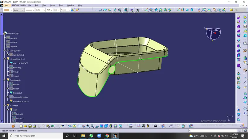
To create an intersection line we have to extract the plane surface and create the point on it and insert an axis system
by using the intersection command with the input of the plane along with the surface. as output, the single line will be visible along the surface with the line we can observe the draft of the lines easily.
in this cat part, none of the walls is having a draft, which means every wall is at 0deg, For components like this, we can simply draw the tooling axis normal to the surface.
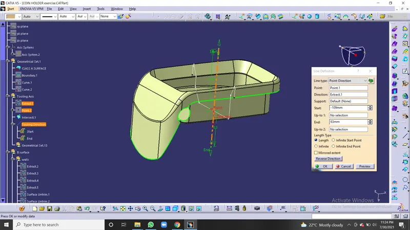
Draft analysis on Class A surface-
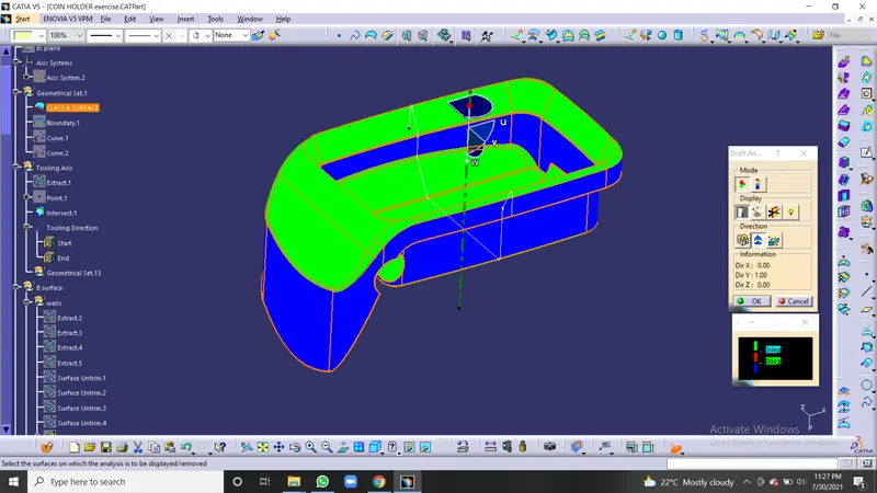
Draft analysis compass is used to define the draft direction.
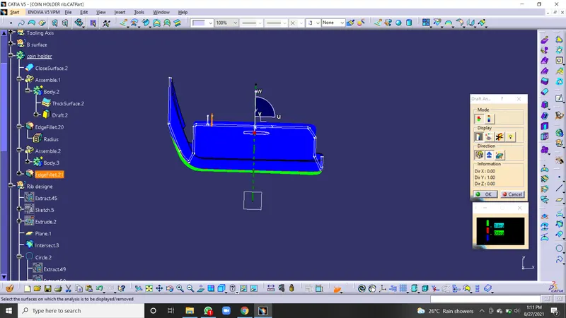
check whether the minimum draft of 3deg is assumed or not. the minimum draft of 3 deg is provided with the whole component changes into green colour.
Rib design-
Ribs are used to strengthen the walls of the mould without increasing the overall wall thickness.it is an economical way to increase the stiffness of the component.
they help in-
Locating and arresting components of an assembly
providing alignment in mating parts
acting as stops or guides for mechanisms
ex- headlight
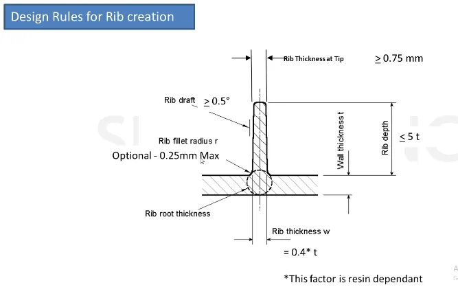
design rules to follow while cretin the ribs-
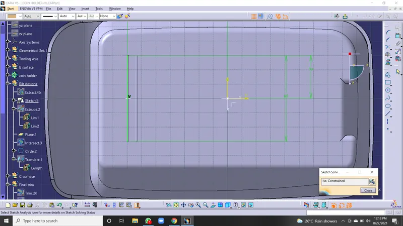
Sketch 1-
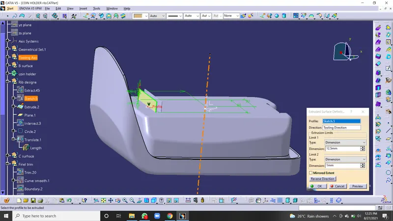
Extruding the sketch-
According to the design rules, the height of the rib should be 5 times the thickness of the component by following the designed rules the sketch will be extruded along with the tooling direction.
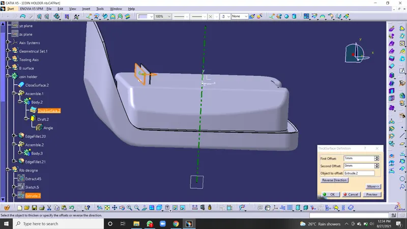
Thickening-
According to the designer rules, the thickness of the rib should be 0.4times the thickness of the component.
Drafting-
the draft of the rib should be 0.5deg
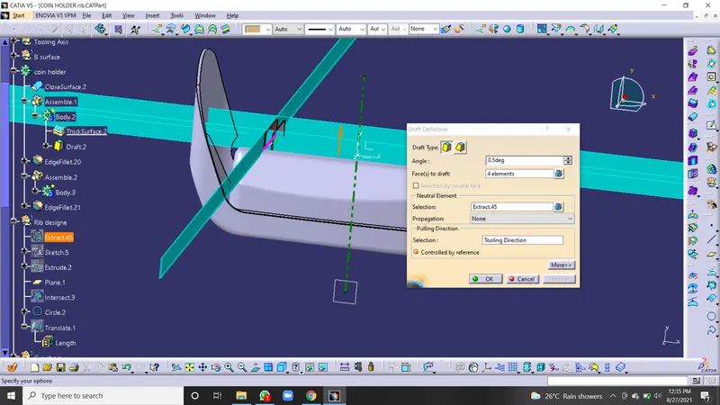
and the rib should be added to the main component.
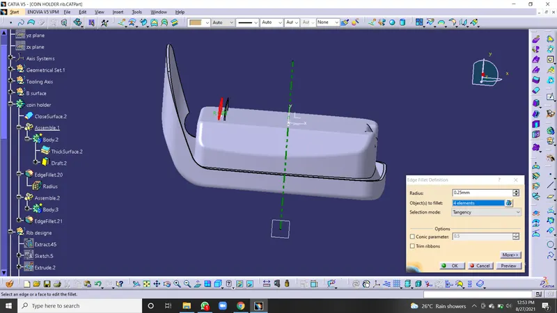
fillets-
rib fillet radius is optimal 0.25mm
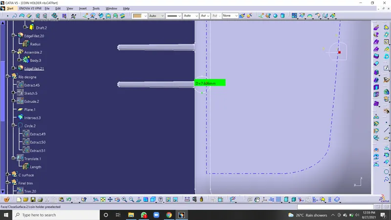
Rib root thickness-
we can check it by creating the intersection with the XY plane and the component using the tri tangent circle.
the top edge of the rib should be greater than the 0.75mm
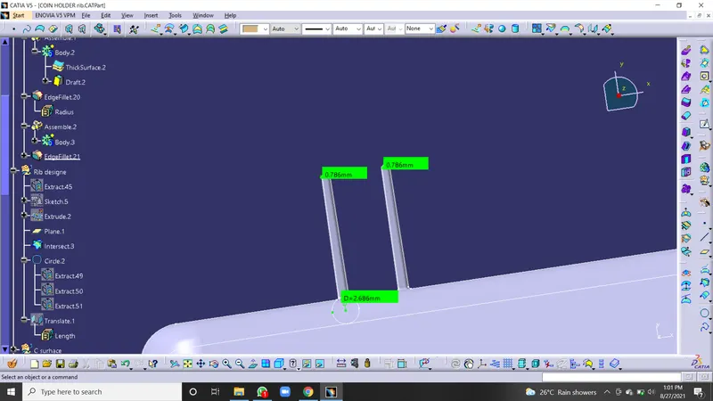
Spacing between two ribs-
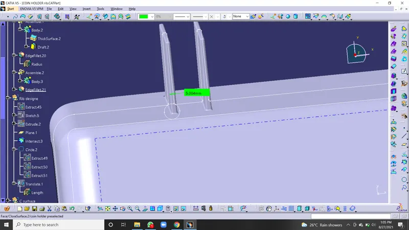
Draft analysis-
The draft analysis will be done after the design of the rib to make sure that it is satisfying the requirement of the design rules.
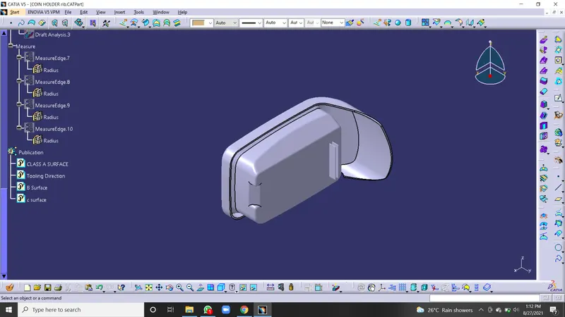
Isometric view-
Front View-
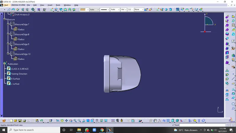
Side View-
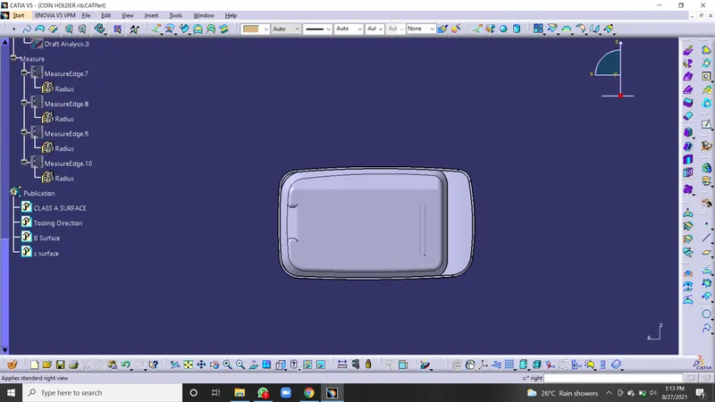
Top View-