Week 8 - Challenge 2 - Base Bracket Design
Tooling Axis-
- Check the Connectivity of class A Surface: these can be done by creating boundaries or by joining command if there are any gaps or openings they will be easily visualized.
-Visually analyse the best possible tooling axis.
-the clearance checking along all the axis on the plane with the model and constructing two lines contact with the walls, the line bisecting the two lines and passing through the point will be the tooling Axis.
Dummy tooling Axis-
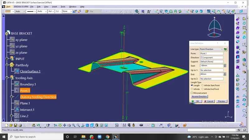
Tooling Axis -By using the two lines created with the help of walls from the interaction created, a bisecting line passing from a point to the two lines will be the tooling axis.
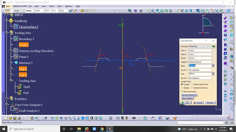 is used to
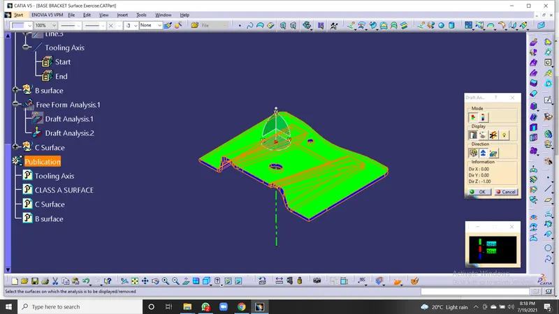
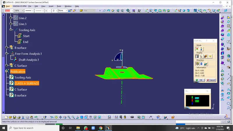
Draft Analysis- check whether the minimum draft of 3deg is assumed or not.
the minimum draft of 3 deg is provided with the whole component changes into green colour.
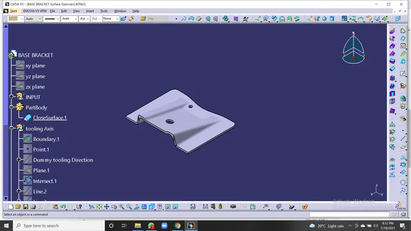
Isometric View-
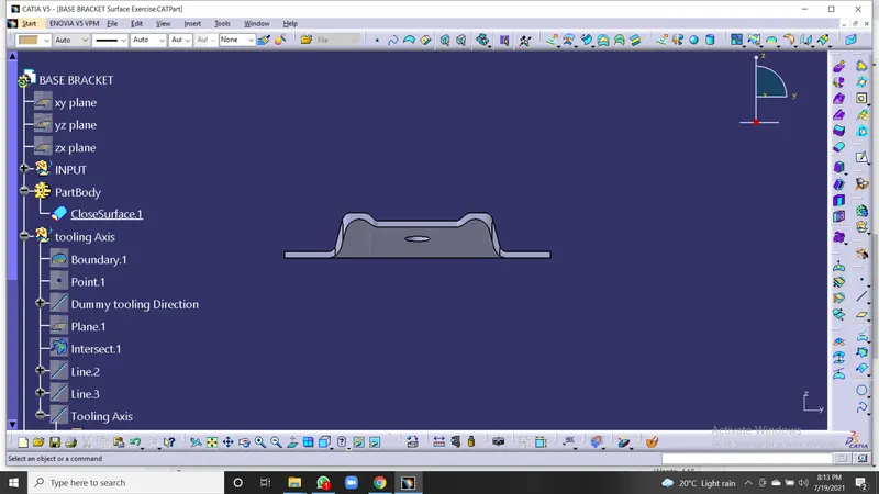
Front View-
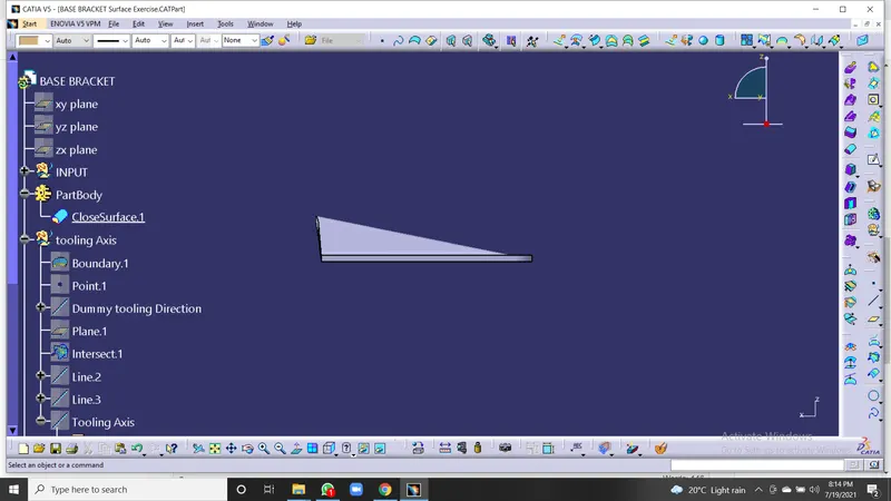
Side View-
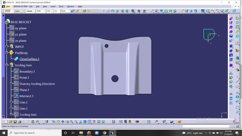
Top View-
B Surface-
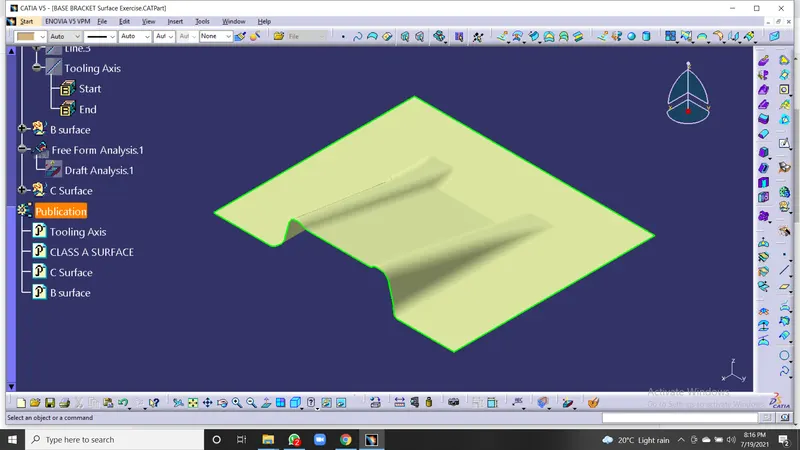
CSurface-
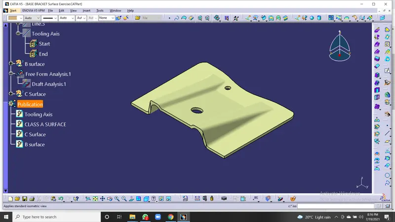
Draft Analysis on solid Component-