Creating 3D Isometric view of various structural elements in AutoCAD
1.
Aim: To draw the Plan and creating it as a 3D Elevation using AutoCAD
Procedure:
Open AutoCad
Selecting Imperial system
Command UN(units) and selecting Engineering with precision of O'-0.0"
Command LIMITS and having limit of (0,0') in lower left corner and (100,100') in upper right corner
Command ZOOM and selecting All
Commands used:
LINE, OFFSET, PLINE, TRIM, RECTANGLE
These commands are used to draw the plan and Windows with its dimensions
REGION
REGION is used to create the region of the plan walls
REGION is used to create the region of the Floor
BOUNDARY
BOUNDARY is used to create the boundary of the region created by picking the points.
EXTRUDE
EXTRUDE is used to extrude the walls created as a boundary to a height of 10'
EXTRUDE is used to extrude the Floor created as a boundary to a height of 4"
EXTRUDE is used to extrude the Ceiling created as a boundary to a height of 6"
LAYER
LAYER is used to crate the layer of different components like 3D Wall, 3D Window,3D window mullion, 3D Glass etc
3DORBIT
3DORBIT is used to see the 3D plan in the desired direction
3DROTATE
3DROTATE is used to rotate the window created in the xz plane to xy plane
EXTRUDE
EXTRUDE is used to extrude the window created as a boundary to a height of 9"
EXTRUDE is used to extrude the window glass created as a boundary to a height of 7"
LAYER
LAYER is used to assign the different layers created to the different components with differnt colours to distinguish.
2.
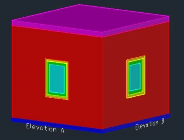
Aim: To draw the Plan and creating it as a 3D Elevation using AutoCAD
Procedure:
Open AutoCad
Selecting Imperial system
Command UN(units) and selecting Engineering with precision of O'-0.0"
Command LIMITS and having limit of (0,0') in lower left corner and (100,100') in upper right corner
Command ZOOM and selecting All
Commands used:
LINE, OFFSET, PLINE, TRIM, RECTANGLE
These commands are used to draw the plan and Windows with its dimensions
REGION
REGION is used to create the region of the plan walls
REGION is used to create the region of the Floor
BOUNDARY
BOUNDARY is used to create the boundary of the region created by picking the points.
EXTRUDE
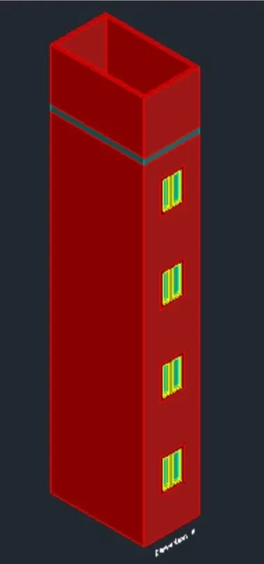
EXTRUDE is used to extrude the walls created as a boundary to a height of 40'-8"
EXTRUDE is used to extrude the Floor created as a boundary to a height of 4"
EXTRUDE is used to extrude the Ceiling created as a boundary to a height of 6"
LAYER
LAYER is used to crate the layer of different components like 3D Wall, 3D Window,3D window mullion, 3D Glass etc
3DORBIT
3DORBIT is used to see the 3D plan in the desired direction
3DROTATE
3DROTATE is used to rotate the window created in the xz plane to xy plane
EXTRUDE
EXTRUDE is used to extrude the window created as a boundary to a height of 9"
EXTRUDE is used to extrude the window glass created as a boundary to a height of 7"
3.
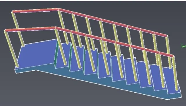
Aim: To draw the staircase and creating it as a 3D using AutoCAD
Procedure:
Open AutoCad
Selecting Imperial system
Command UN(units) and selecting Engineering with precision of O'-0.0"
Command LIMITS and having limit of (0,0') in lower left corner and (100,100') in upper right corner
Command ZOOM and selecting All
Commands used:
LINE, OFFSET, PLINE, TRIM, RECTANGLE
These commands are used to draw the Thread and Risers with its dimensions as 12" and 6" respectively in Staircase
REGION
REGION is used to create the region of the Thread and Risers
REGION is used to create the region of the Handrails and Baluster
BOUNDARY
BOUNDARY is used to create the boundary of the region created by picking the points.
EXTRUDE
EXTRUDE is used to extrude the Thread and Risers created as a boundary to a distance of 3'
EXTRUDE is used to extrude the Handrails created as a region
EXTRUDE is used to extrude the Baluster created as a region
LAYER
LAYER is used to crate the layer of different components like Handrails, Baluster, Thread
and Risers
3DORBIT
3DORBIT is used to see the 3D plan in the desired direction
CYLINDER
CYLINDER is used to create a cylinder a cylinder of height 3'-2" to create the
baluster
SWEEP
SWEEP is used to sweep the cylinder with the path to create the Handrails
3DROTATE
3DROTATE is used to rotate the window created in the xz plane to xy plane
EXTRUDE
EXTRUDE is used to extrude the window created as a boundary to a height of 9"
EXTRUDE is used to extrude the window glass created as a boundary to a height of 7"
LAYER
LAYER is used to assign the different layers created to the different components with differnt colours to distinguish.
4.
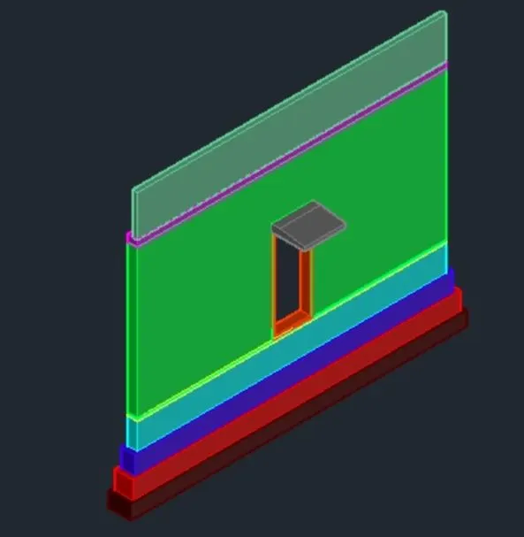
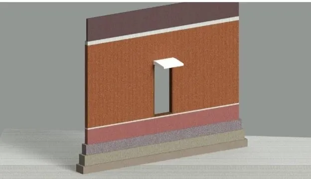
Aim: To draw the footing with wall and creating it as a 3D Elevation using AutoCAD and Render it
Procedure:
Open AutoCad
Selecting metric system
Command UN(units) and selecting decimals with precision of O
Command LIMITS and having limit of (0,0) in lower left corner and (10000,10000) in upper right corner
Command ZOOM and selecting All
Commands used:
LINE, OFFSET, PLINE, TRIM, RECTANGLE
These commands are used to draw the footing with wall with its dimensions
REGION
REGION is used to create the region of the Stepped footing as a separate
region
REGION is used to create the region
of the wall
BOUNDARY
BOUNDARY is used to create the boundary of the region created by picking the points.
EXTRUDE
EXTRUDE is used to extrude the Stepped footing created as a boundary to a height of 300,400,400 and 600 respectively
EXTRUDE is used to extrude the wall created as a boundary to a height of 3300
EXTRUDE is used to extrude the parapet wall created as a boundary to a height of 600
EXTRUDE is used to extrude the floor created as a boundary to a height of 50
EXTRUDE is used to extrude the ceiling created as a boundary to a height of 150
LAYER
LAYER is used to crate the layer of different components like 3D Wall, 3D Window, 3D window mullion, 3D Glass etc
3DORBIT
3DORBIT is used to see the 3D plan in the desired direction
3DROTATE
3DROTATE is used to rotate the Door and Chejja created in the xz plane to xy plane
SLICE
SLICE is used to slice the chejja with its
front size to 50
EXTRUDE
EXTRUDE is used to extrude the window created as a boundary to a distance of 230
EXTRUDE is used to extrude the window glass created as a boundary to a distance of 100
LAYER
LAYER is used to assign the different layers created to the different components with differnt colours to distinguish.
MATERIAL BROWSER
MATERIAL BROWSER is used to browse the appropriate materials to different components and assign it to create a rendering view
RENDER TO SIZE
RENDER TO SIZE is use to select the
quality of the rendering view and selecting FULLHD resolution 1920X1080p