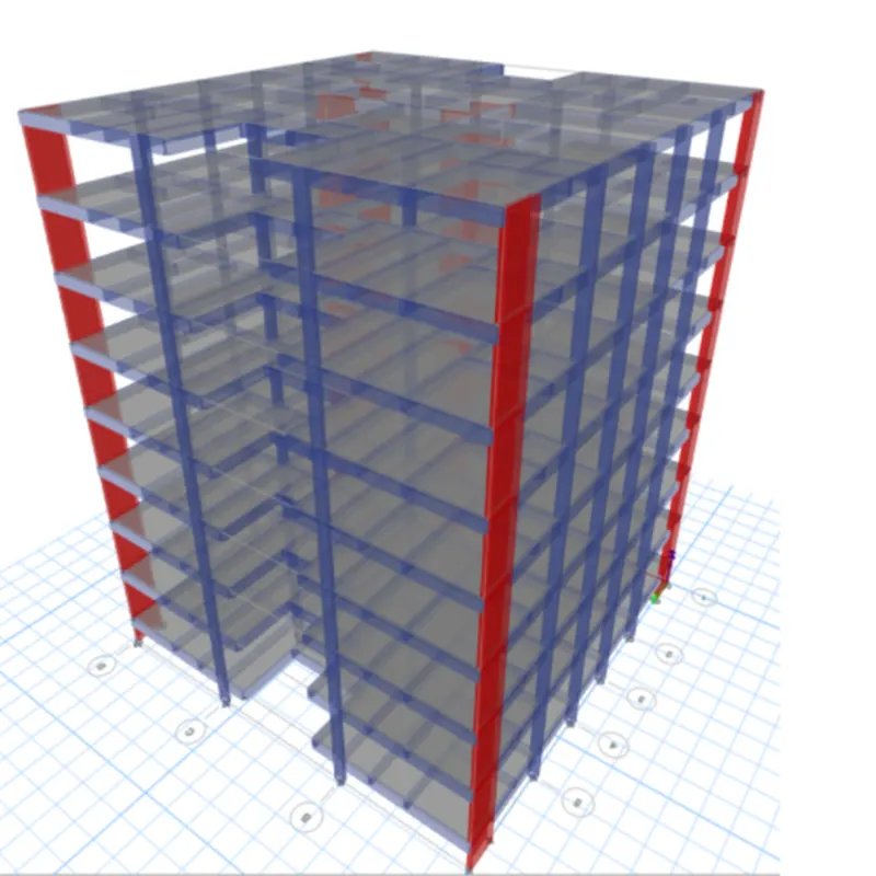
Structural Modelling using Etabs 2018
Aim - To model and analyze the residential building using Etab
Procedure -
Step 1 -
- First open Etab software
- Select new model from file menu
- After selecting new model,new tab open and select Use Built in setting
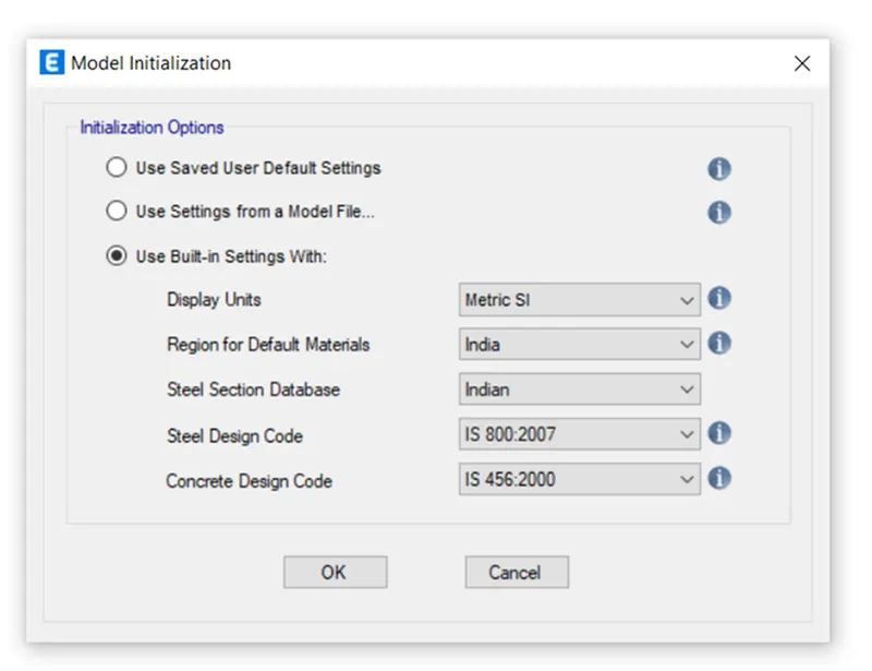
- Then select grid,and do the setting in grid system data
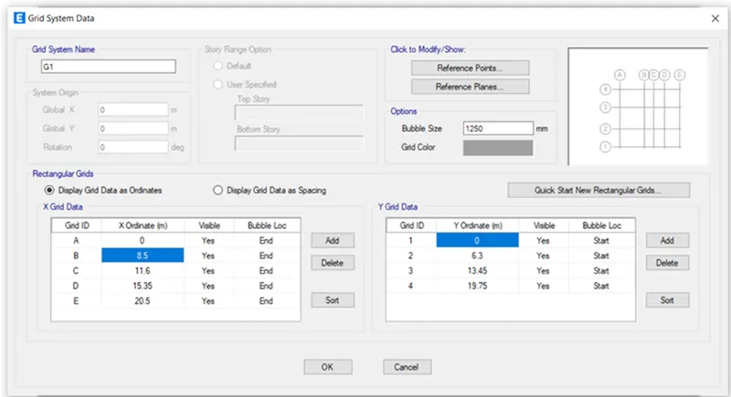
- After grid setting,Add the 7 story in the story data table
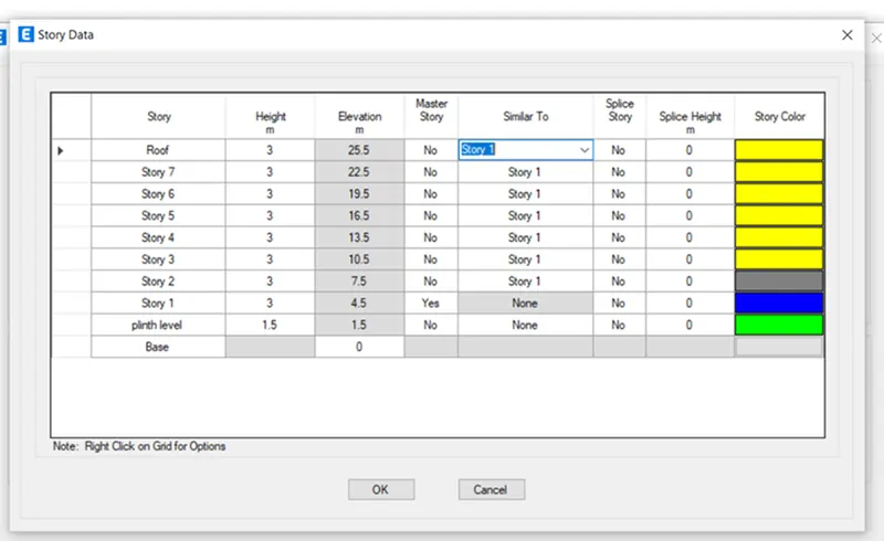
Step 2 -
- The plan view and 3D view are visible
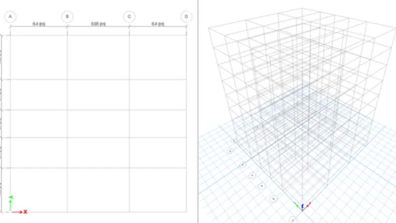
Step 3 -
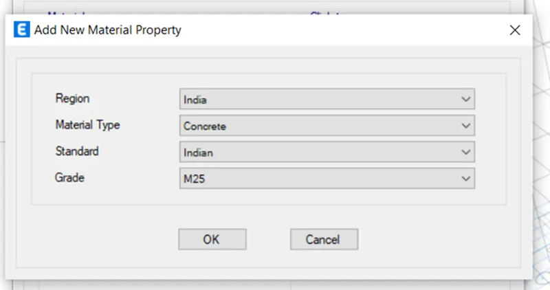
- Select material properties from define menu option
- For concrete material choose M25 grade and standard as Indian
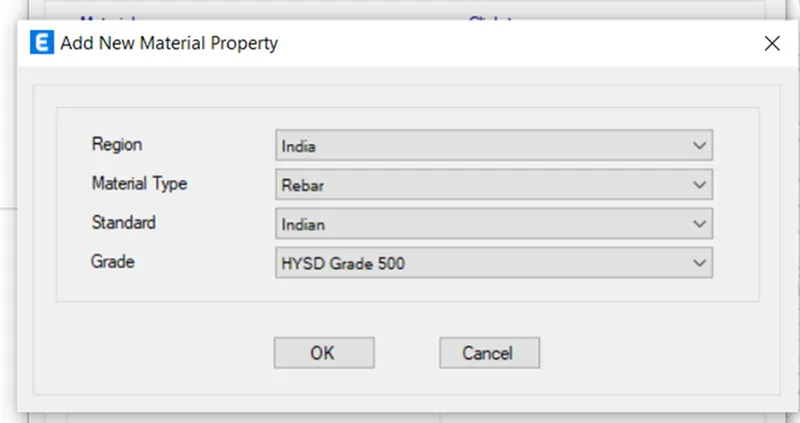
- Add new material type as Rebar and grade as HYSD 500
- Check the material property
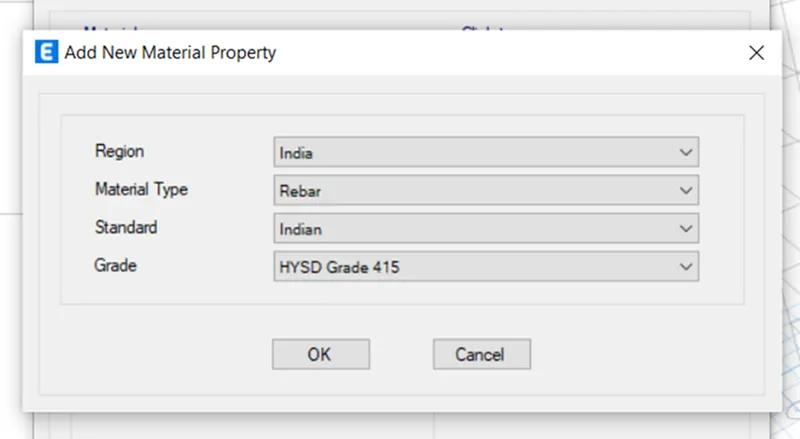
- Add new material property Rebar as grade HYSD 415
- And check the material property
Step 4 -
- After selecting material properties,we select section properties and choose frame section
- After selecting frame section we add new property,in that tab select Rectangular shape concrete type
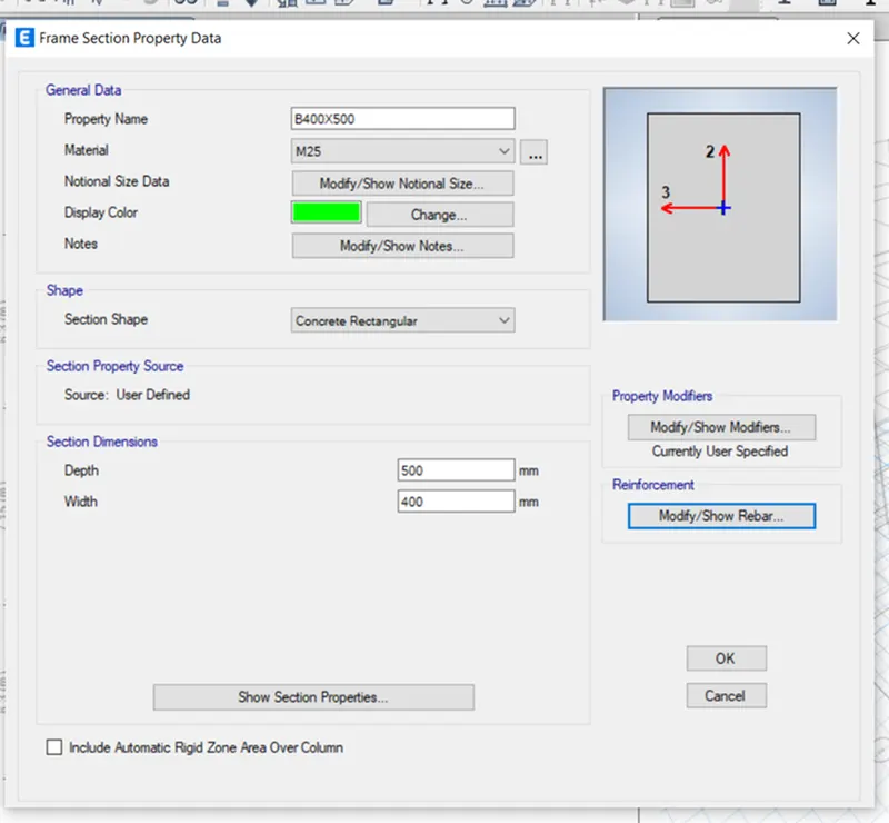
- Add beam size of B400x500,and select modify /show modifiers and modify show rebar
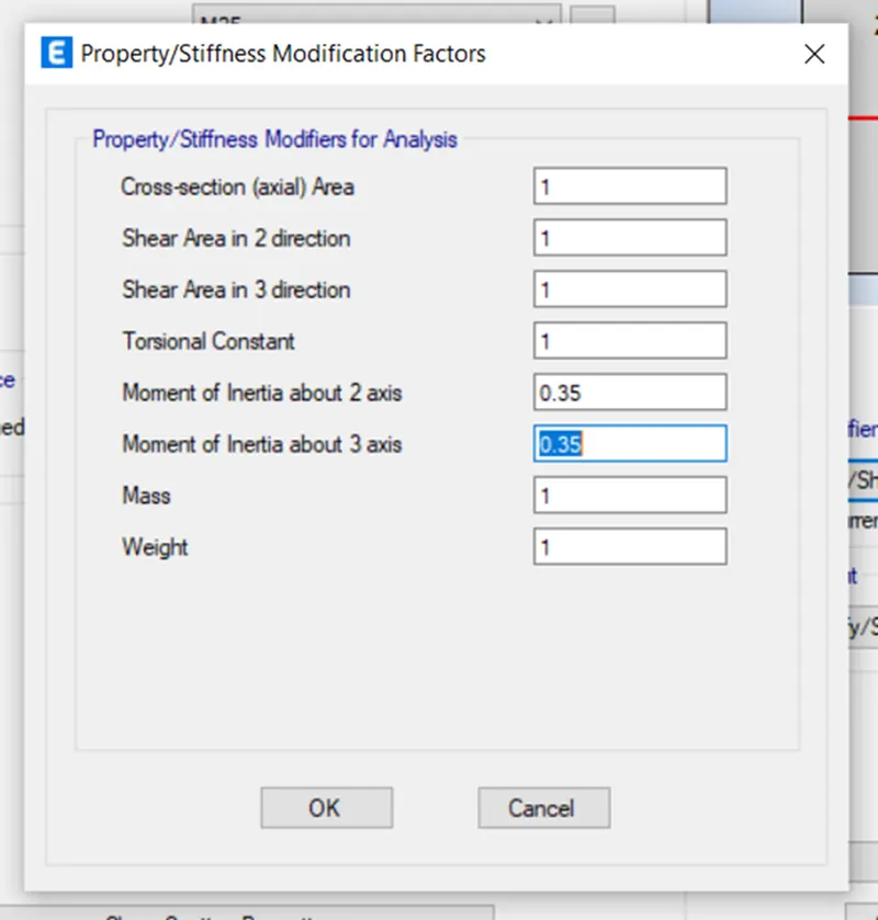
- In stiffness modification factor select moment of inertia about 2 axis =0.35 and moment of inertia about 3 axis =0.35
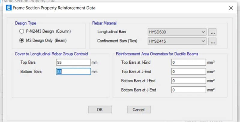
- After selecting modify/show rebar option,select design type as M3 design only 9 (beam)
- Longitudinal bars as HYSD500 and confinement bars as HYSD 415
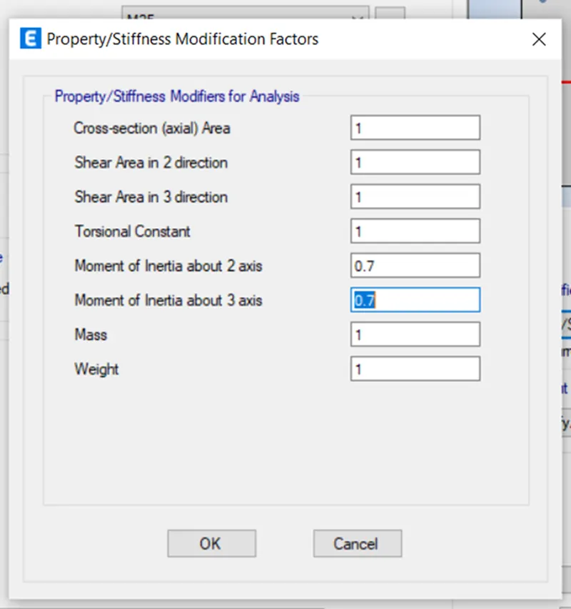
- Add new section property as C450x600
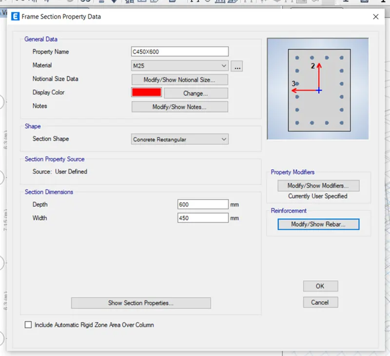
- In stiffness modification factor select moment of inertia about 2 axis =0.7 and moment of inertia about 3 axis =0.7
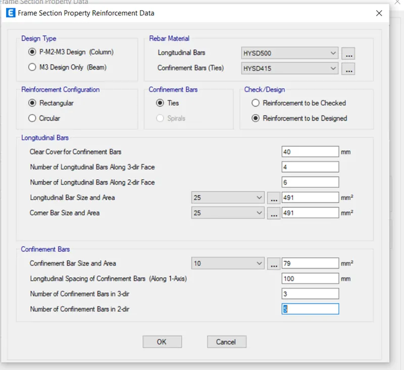
- After selecting modify/show rebar option,select design type as P-M2-M3 design (column)
- Longitudinal bars as HYSD500 and confinement bars as HYSD 415
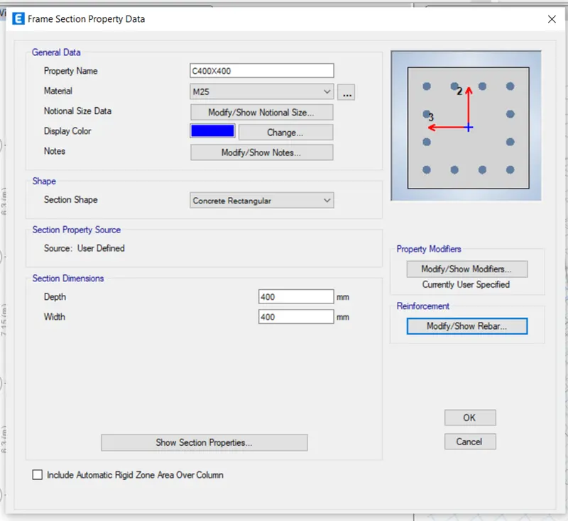
- Again add section property as C400x400
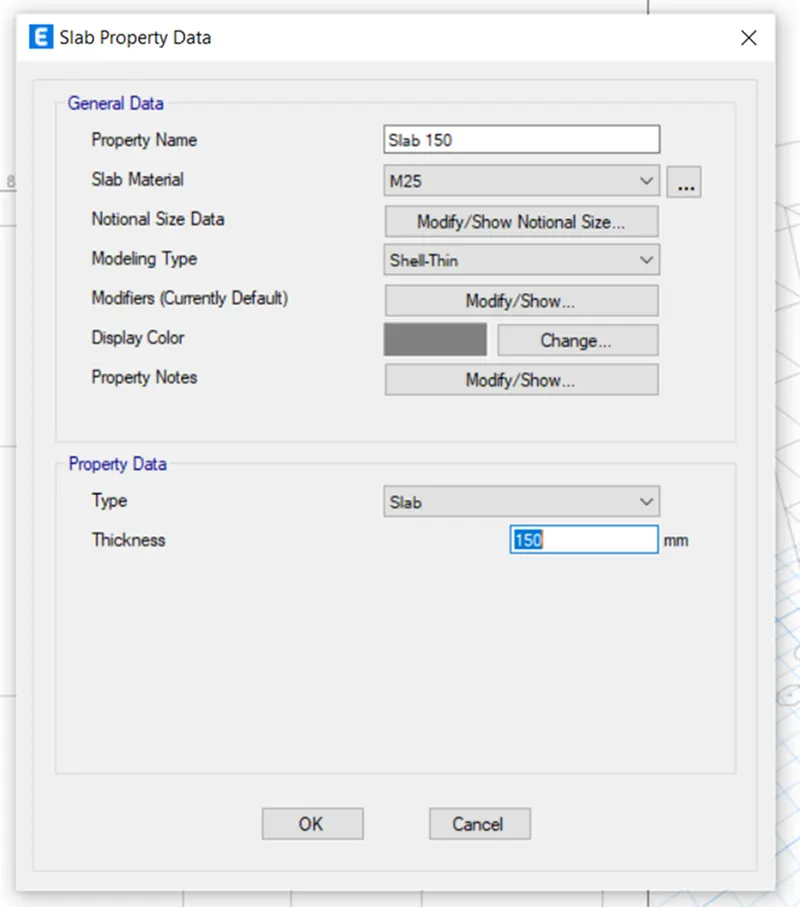
- Now select slab section property from the section option
- Select modify/show property
- Put the slab property as Slab150mm thickness and then ok
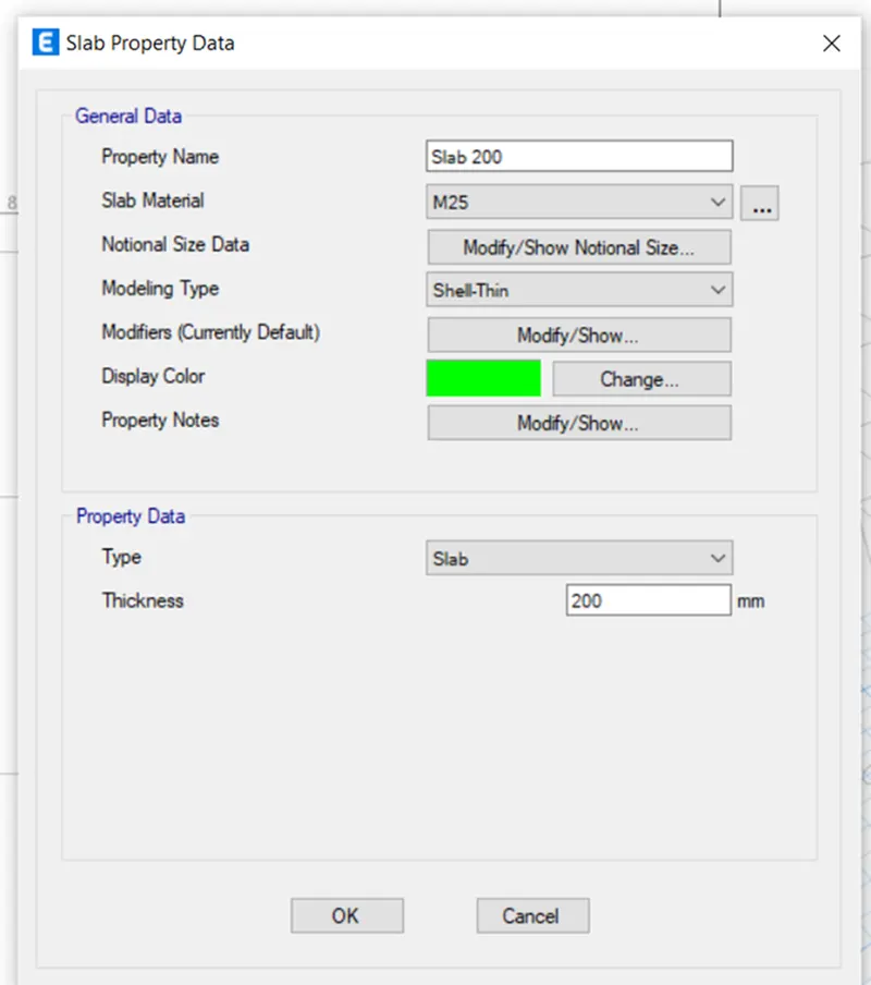
- Now for staircase,again add slab property as slab200 mm thickness
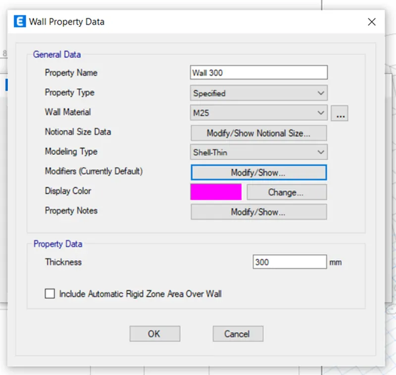
- Now add wall property as Wall 300mm
Step 5 -
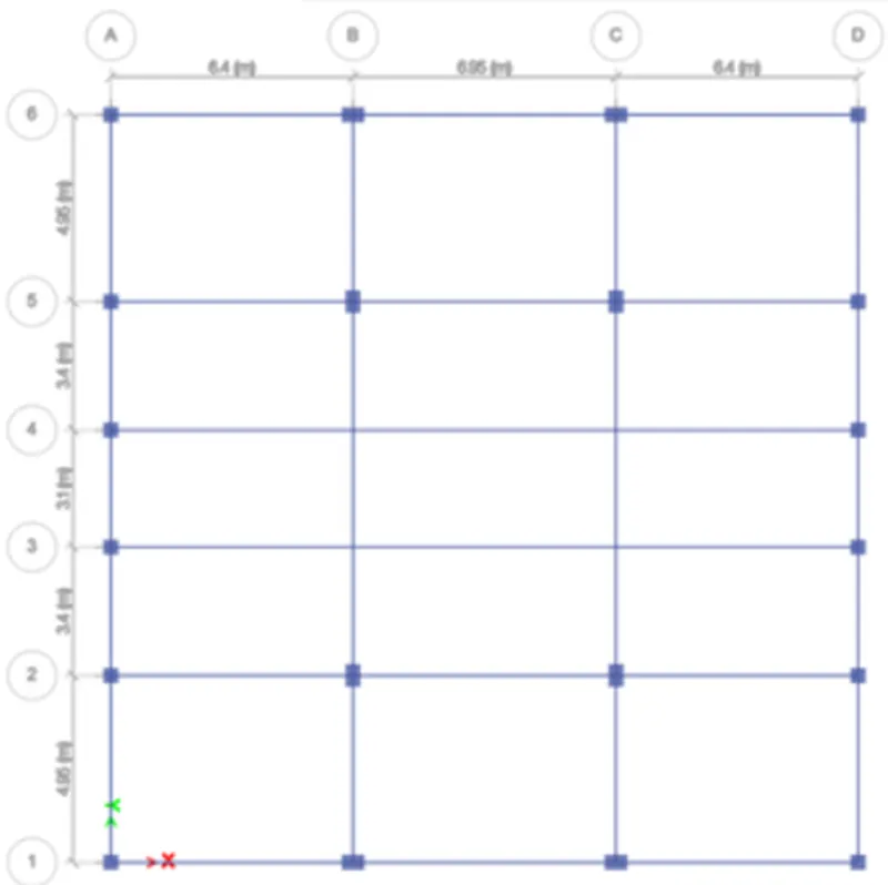
- Next we add column using quick draw column option
- After that,we add beam using quick draw beam option
Step 6 -
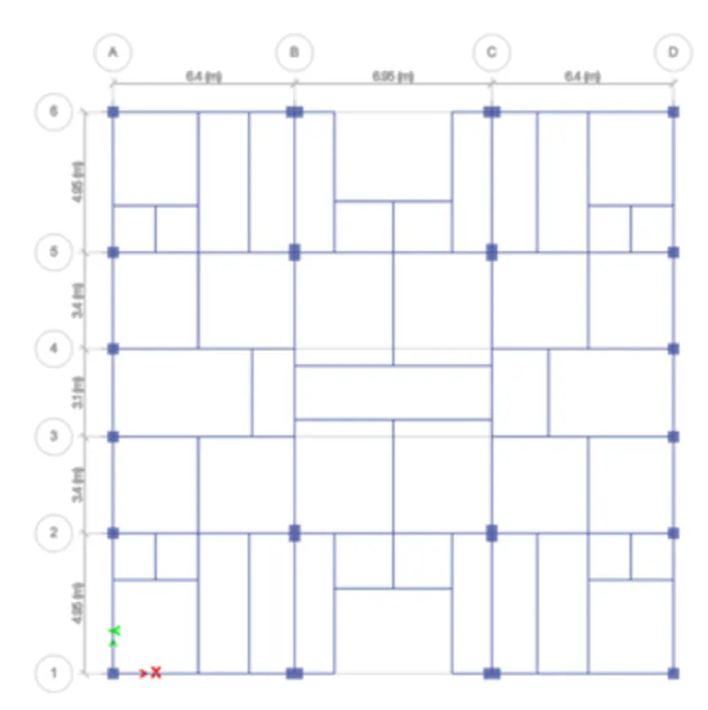
- Draw secondary beam using quick draw beam option
Step 7 -
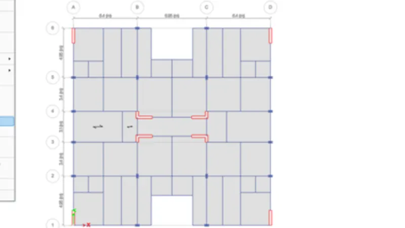
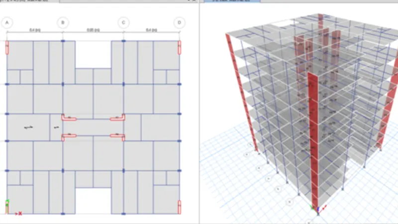
- Now draw shear wall in plan view using draw wall option
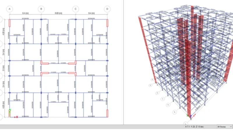
Step 8 -
- Add slabs using quick draw floor/wall option
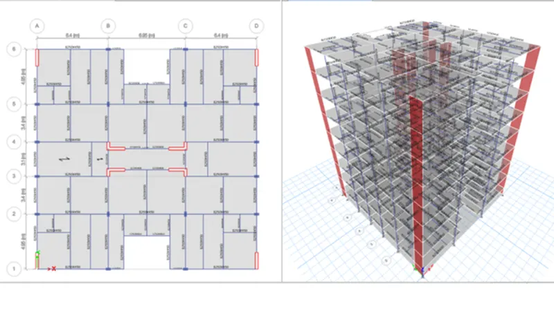
Step 9 -
- Now select base plan,and select all joints and then restraints from join option
- Select pinned support and then apply and ok
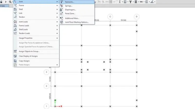
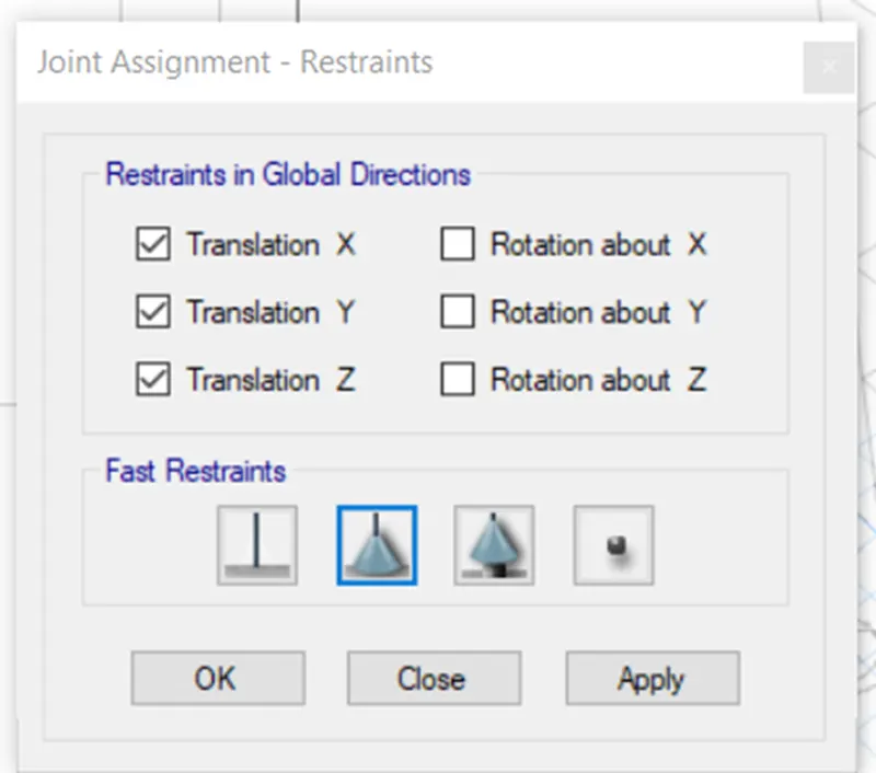
Step 10 -
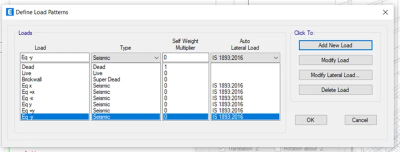
- Now add load pattern from the define option
- Add dead load,live load,brickwall load and earthquake load
Step 11 -
- Next add distributed load from frame load,in that select brickwall as load pattern and put uniform load value 3.5kn/m
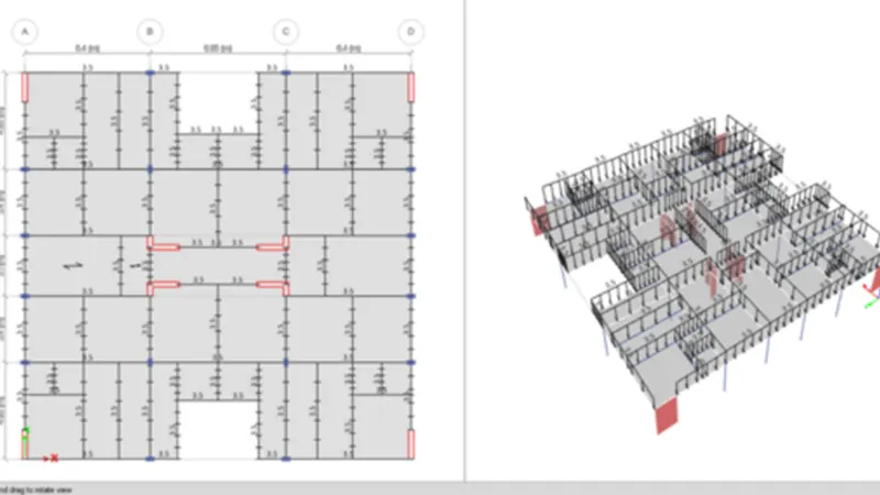
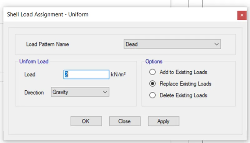
- Select assign option and then select shell load and then uniform option
- Add live load as 3kn/m^2 for stairscase and lift
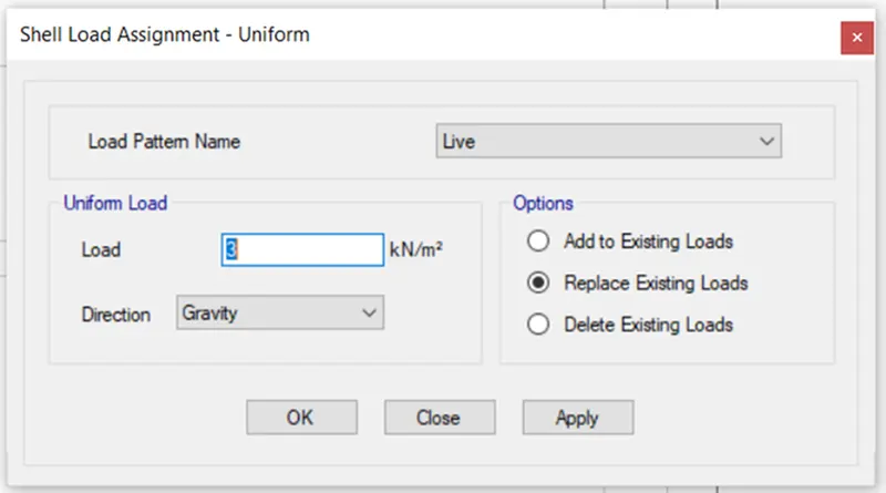
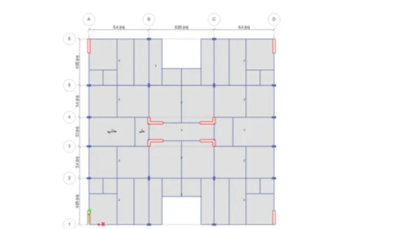
- Again add live load as 2kn/m^2 for all building
Step 12 -
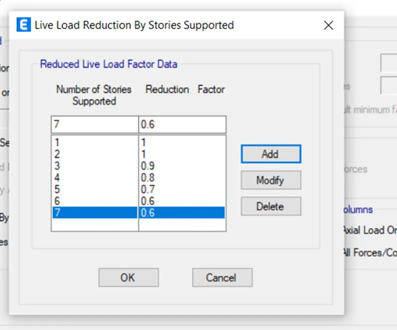
- Now select live load reduction factor from design option
- Add reduction factor by 10% decrease in live load
Step 13 -
- Select mass source from define option
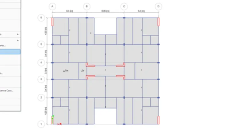
- Add load pattern in mass source data
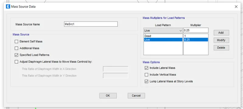
Step 14 -
- Now select object type option from select option
- After selecting the object type option,new tab will be visible and in that,select floors and then select and close
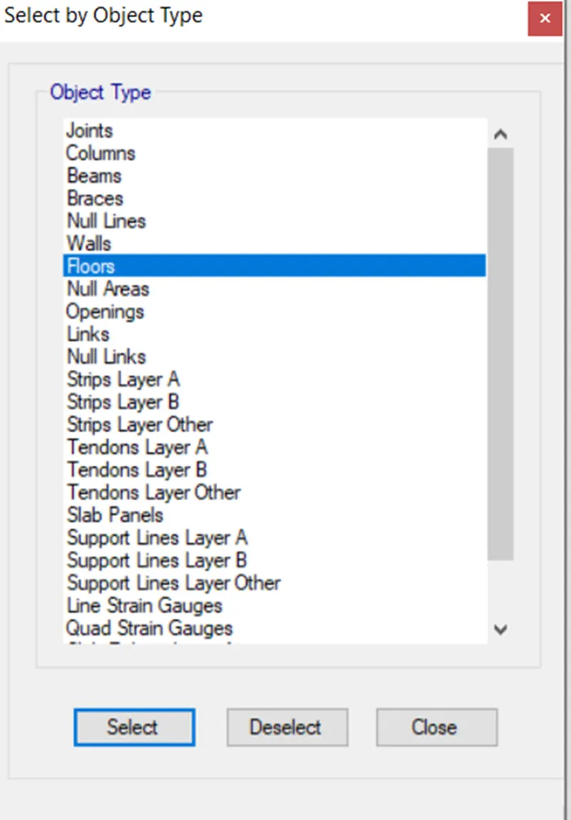
Step 15 -
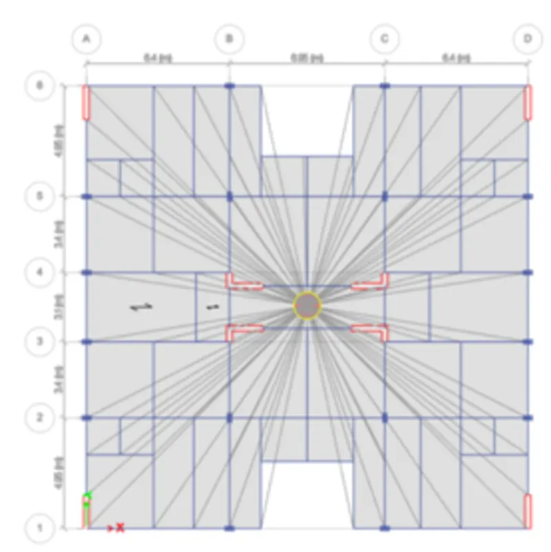
- Then select Diaphragms form shell option
- New tab will appear,in that select D1 and click on apply and close
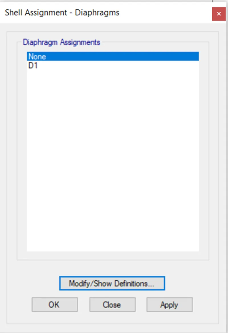
Step 16 -
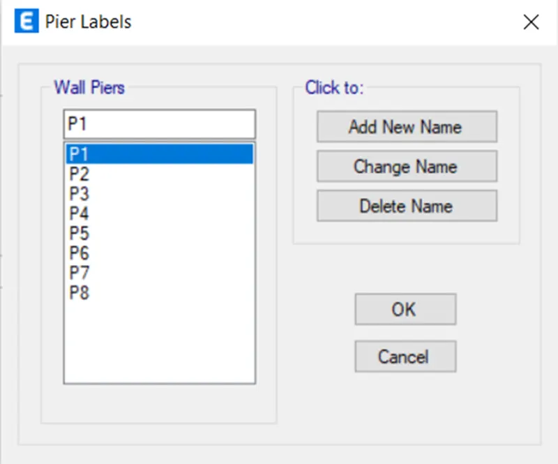
- Next select the pier lable from the shell option
- Assign the names for shear wall as p1,p2,p3,p4,p5,p6,p7
Step 17 -
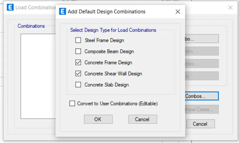
- Next select load combinations from define tab
- In that,select Add default design combo option
- After that,select concrete frame design and concrete shear wall design
Step 18 -
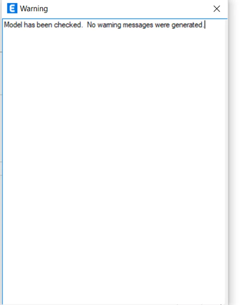
- Check the model by clicking the check model option from display option
- The model is checked,and warning message is shown
Step 19 -
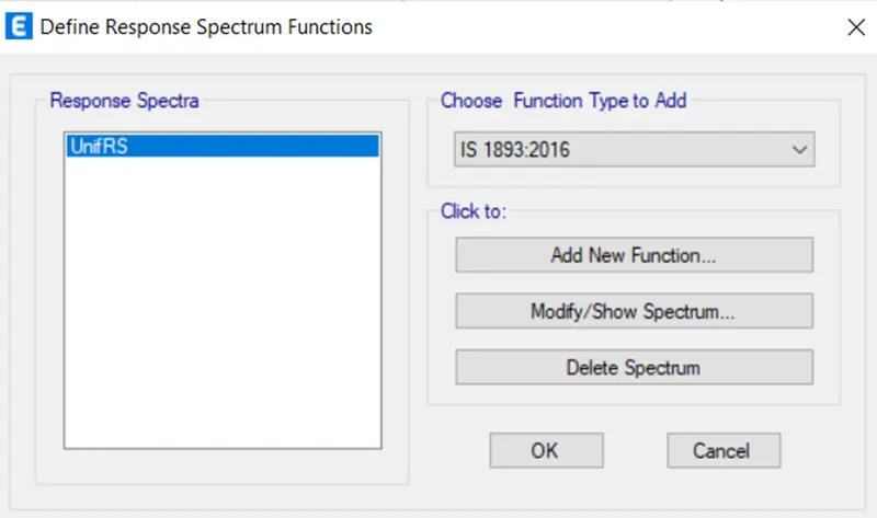
- Select define option,in that select function and then select response spectrum
- After selecting new tab is visible,in that choose IS 1893-2016 form choose function type and then selec, modify/show spectrum
- After selecting modify/show spectrum option new tab will visible,in that give name as IS FUNCTION
Step 20 -
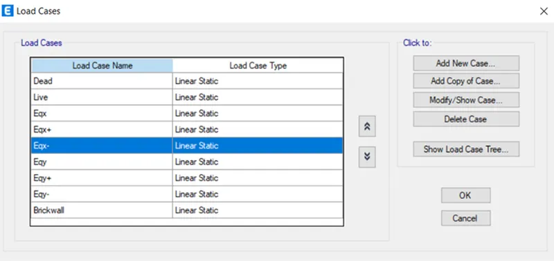
- Next select load cases from the define option
- Load case tab is visible,in that select the Add new case
- Add details of load case data
Step 21 -
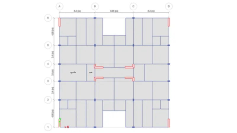
- Now,Run analysis
Step 22 -
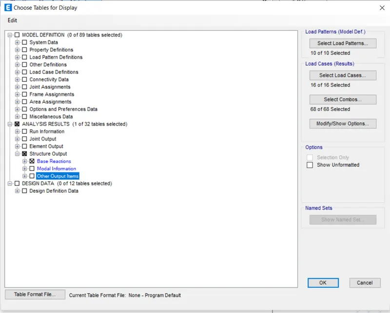
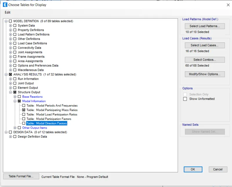
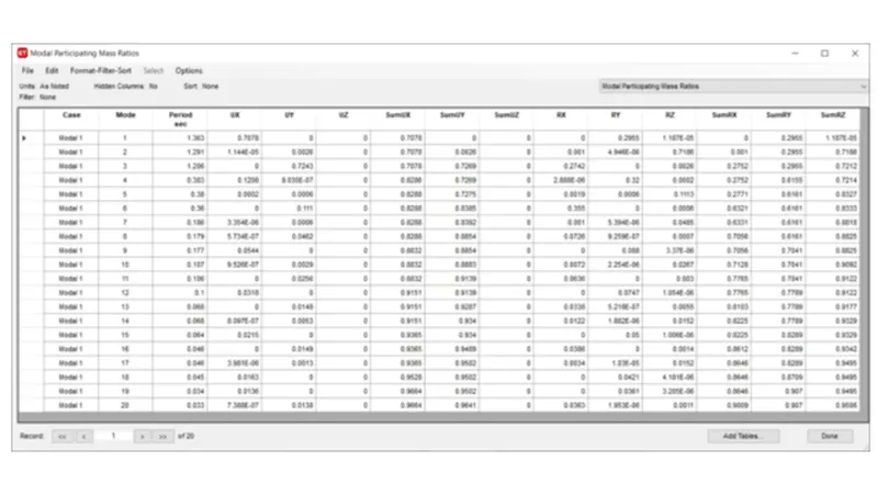
- From display option select show table option
- In that,select analysis result-structure output and then base reactions and ok
- The base reaction table will appear

Step 23 -
- From display option select show table option
- In that,select analysis result-structure output and then base reactions and ok
- The base reaction table will appear
Step 24 -
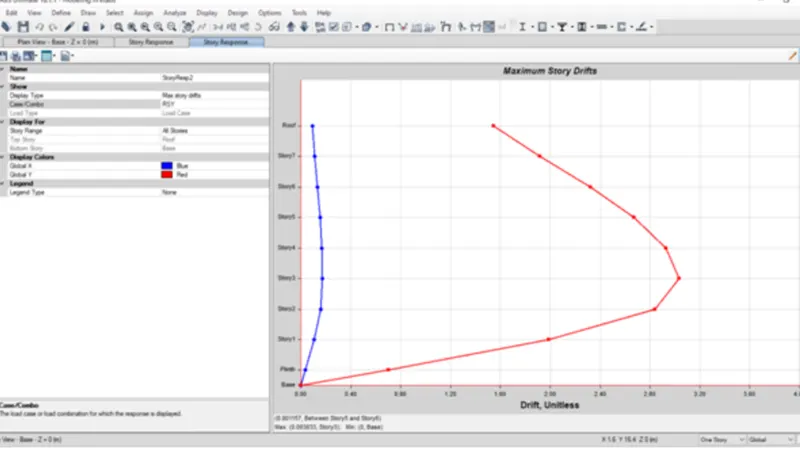
- Select story response plot from the display option
Step 25 -
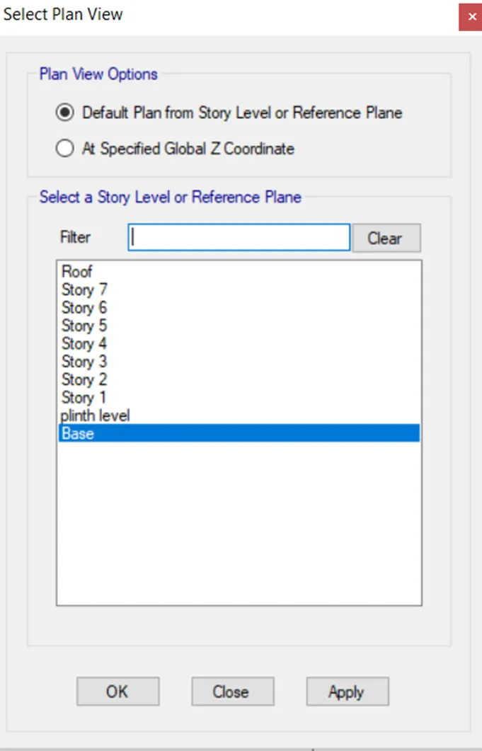
- Select plan view option and in that open base floor plan
- Then open reaction tab and select earthquake load
- Now base shear reaction will appear
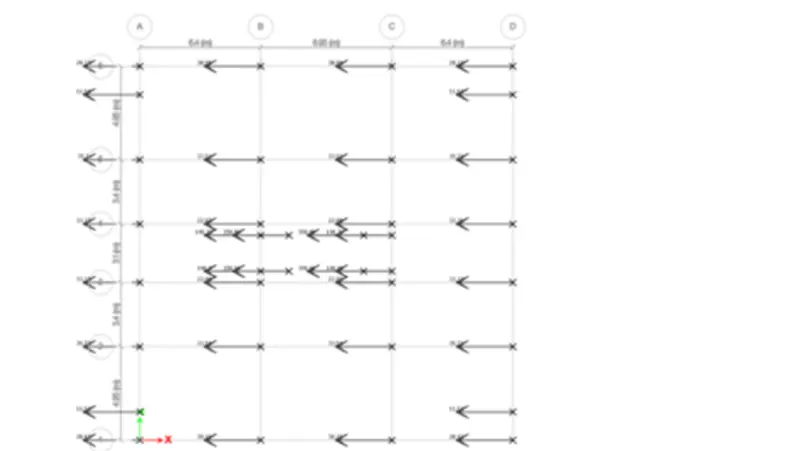
Result -
- The G+7 residential building has been modelled and analyzed successfully.