Week 1 Challenge
1.
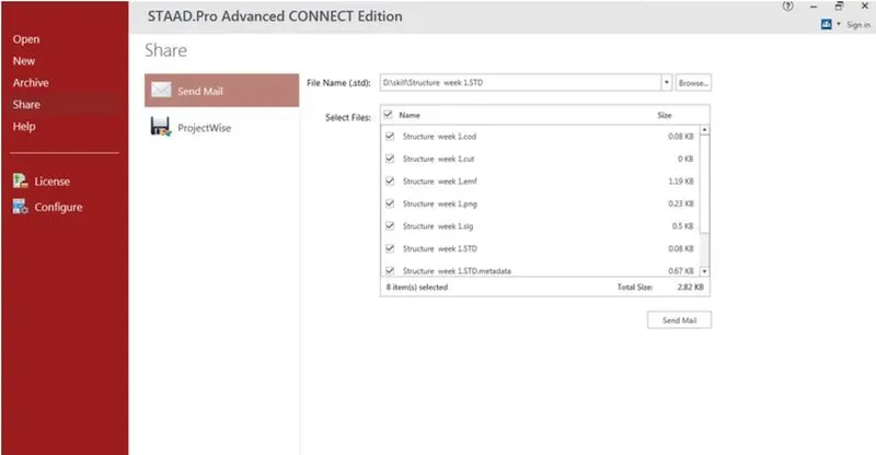
1. Write the steps involved to upload a .std file through web mail?
Ans:
- Go to mail.
- Compose your mail.
- Click on attach and upload your file there.
- Ensure that you are log in to mail
2. Name the different materials that can be designed using STAAD Pro.
Ans: The material that can be designed using STAAD Pro are
- Concrete
- Steel
- Timber
- Aluminium
- Composite section
3. Is it possible to capture images in STAAD Pro? If yes how?
Ans: Yes
For capture image in STAAD Pro use picture command

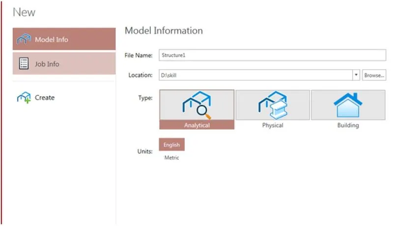
4. Name the three ways by which you can create a model.
Ans:
- Analytical
- Physical
- Building
5. Write the steps followed to assign properties in a model.
Ans: Go to roperties tab
- For Concrete---> Define--->Rectangle--->Enter dimension in x and y
- For Steel---> Section database--->Indian---> Choose section
2.
1. Name any six design parameter involved in RCC design.
Ans:
- Ultimate tensile strength of steel - FU
- Yield strength of steel - FY
- Effective length factor - Kx Ky Kz
- Length for torsional buckling - LX Ly LZ
- Allowable L / R in comprssion - MAIN
- Max allowable local deflection - DFF
- Clear cover
- Cmpressie strength of concrete - Fck
2. What are the different cursor types available in STAAD Pro?
Ans:
The cursor availlable are
Right click and select cursor the option are available
- Node cursor
- Bema cursor
- Plate cursor
- Surface cursor
- Solid Cursor
- Plate and Solid cursor
- Geomatric cursor
- Physical membrane
3. How will you generate different views for a model? State the steps involved.
Ans:
Go to view option in the ribbon there we can get option like
- Top view
- Isometric view
- Front view
- Left view
- Right View
- Botttom view
- Back view
4. Explain the procedure to define a “Simply Supported” condition in STAAD Pro
Ans:
Go to the support command in the tool palet command
- Click on create support command
- There we can get option like fixed support , pin support , Fixed but
- Enforced but support
- Cable support
- Inclined support
5. Name any five topics that you will include while creating DBR.
Ans:
DBR Design basis report
- To take up a project from the scrach to the end this is need
- To specify the data and compile data recived and analysis and design of structural element
- It contains the assumption and specification to develop the project
- It will help to avoid the scope and the creep that can derail the projec schedule and lead to budget overness
- Contains the general Column drawing
- Contains the projec planning
6. Describe the term “Multi material design” of STAAD Pro.
Ans:
- It is used for 3D model generation, analysis and multi -material design .
- The STAAD .Pro supports several steel , concrete and timber material in a seprate member
- This seprate member will cordinate and the formed in to a structure
3.
1. Name the structure systems in STAAD Pro? Explain each system?
Ans:
They are four structural system in staad pro
Structure System Geometry Loading Deform Joint
Space 3D 3D 3D ANY
Plane 2D 2D 2D ANY
Frame 2D PARPEN TO XZ PERPEN TO XZ ANY
Truss 3D 3D 3D Pinned
2. Explain the coordinate system adopted in STAAD Pro software.
Ans:
They are two coordinate syytem in Staad pro
- Global Axis : Gloabal Axis is fixed in the coordiate system
- Local axis : local axis is variable
- This is used for the orientation of the beam with the load varible
3. Elaborate DBR and its uses.
Ans:
- DBR Design basis report
- To take up a project from the scrach to the end this is need
- To specify the data and compile data recived and analysis and design of structural element
- It contains the assumption and specification to develop the project
- It will help to avoid the scope and the creep that can derail the projec schedule and lead to budget overness
- Contains the general Column drawing
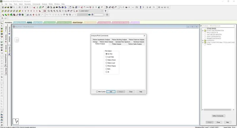
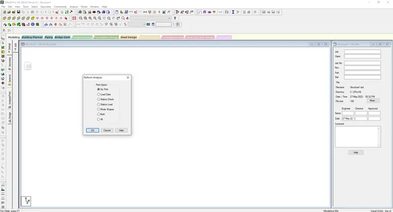
4. Explain the different types of analysis options in STAAD pro.
Ans:
5. Explain the difference between Fixed and Fixed But condition.
Ans:
- In fixed condition the node or the end condition are fixed are restrained with the FX , FY, FZ and the moment are also restrained
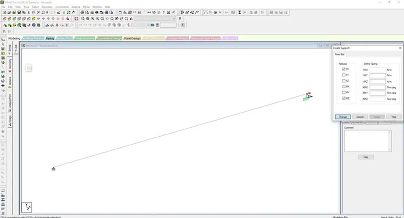
- In Fixed But condition the node are Fx and MZ are released as it is horizontal rolled support
Practical
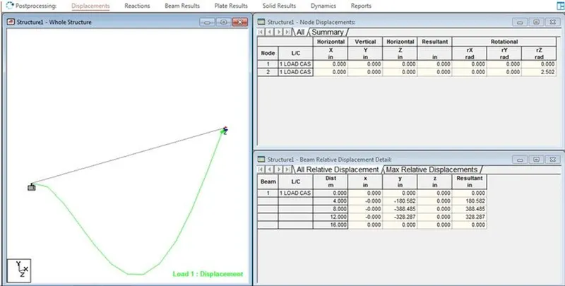
1. Create a STAAD Model with the following Specification
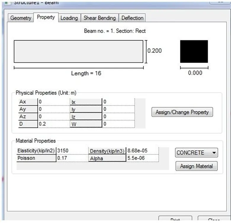
a. A beam of span 16m
b. Support : Fixed on one end and Roller support(Horizontal) on the other end
c. A point load of 50 kN at the mid-point
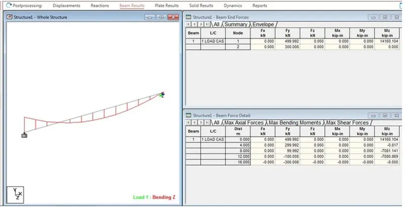
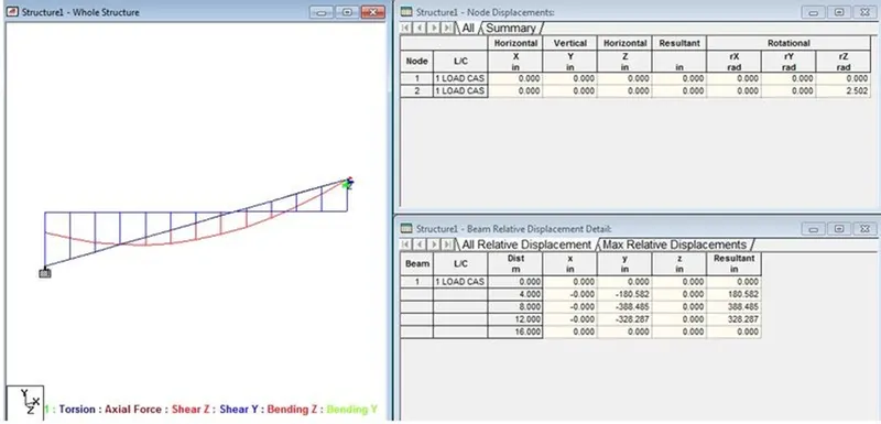
d. Draw SFD and BMD using software
Ans:
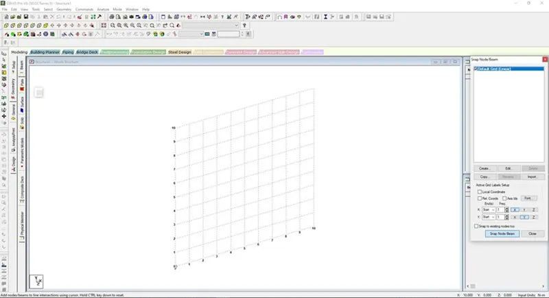
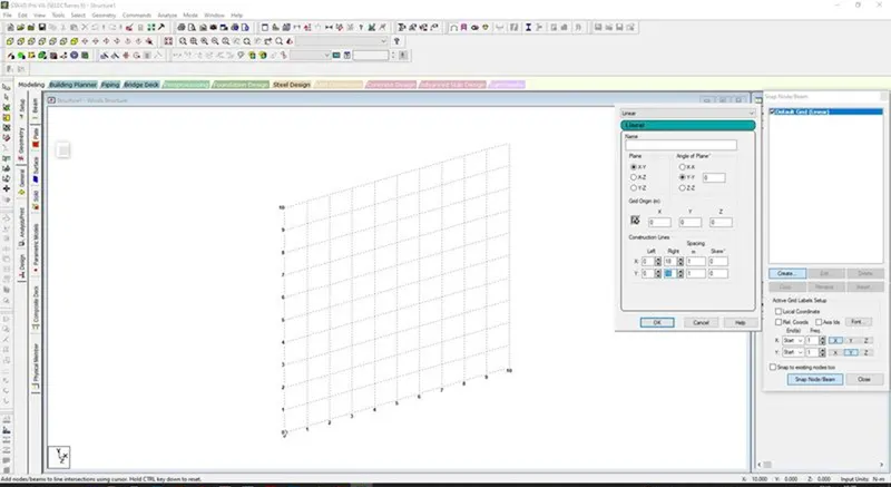
Grid Dimension are to be given spacing as 1 m and in X and Y direction are 18 Grid
- Click on the Grid menu and Draw a beam of span 16 m
- For the node View click on CTRL +N or Right click and labels and view nodes
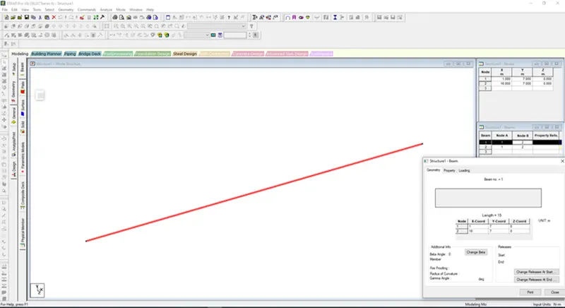
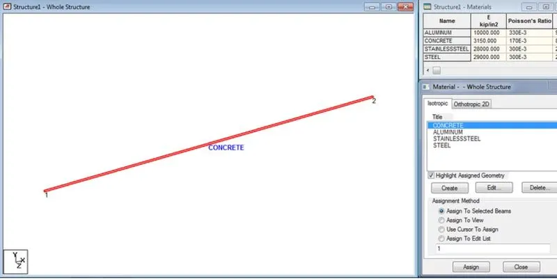
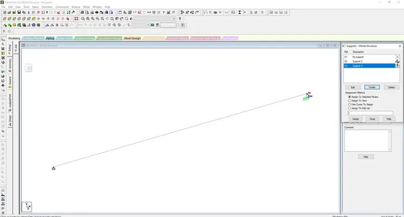
Adding Fixed support and Roller support Horizontal on other end