Conceptual design of a building with columns and shear walls
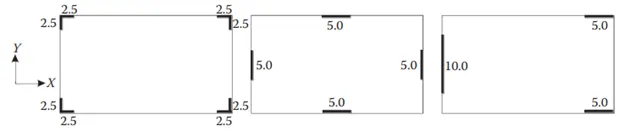
1.The building shown, 20 × 35 m in plan, has columns on a 5 × 5 m grid and shear walls (with dimensions shown in m, 250 mm in thickness) in three alternative arrangements, (a), (b), (c), all with the same total cross-sectional area of the shear walls. Compare the three alternatives, taking into account the restraint of floor shrinkage, the lateral stiffness and the torsional one with respect to the vertical axis, the vertical reinforcement required for the same total flexural capacity at the base, the static eccentricity, the system’s redundancy, foundation systems, architectural constraints etc.
Solution :
In the above 3 alternative arrangements a, b, c :
1. In arrangement 'a' and 'b' shear walls are arranged in symmetrical pattern and 'c' as asymmetrical pattern. Symmetricity ensures shearforce distributed equally, avoid torsional stresses, uniform distribution of seismic force and deformation demands, minimising the uncertainity of seismic response. Hence increasing efficiency.
2. Shear walls in 'a' plan, all walls are of same size similarly in 'b' plan walls are similar. Similar walls ensures yielding takes place at same time. Therefore all walls consists same stiffness which reduces inter storey distortion. 'c' plan has dissimilar walls in which the stronger and stiffer ones will yield first, imposing on the rest theirs inelastic deflection pattern, notable one where storey drifts increase almost linearly to the top owing to rotation of the plastic hinge at the base while the walls that are still elastic tend to deflect as vertical cantilevers. In this case besides the increased uncertainity of the post elastic response, the floor diaphragms will be stressed hard to iron out the differences in height wise deflection patterns between the stiffer walls, which have gone in elastic and the more flexible ones, which remain elastic.
3. In plan 'a' shear walls runs into or crosses another wall at right angles to create a wall with a composite cross section of more than one rectangular parts. Such walls ('L' shape ) have high stiffness and strength in both horizontal directions hence are subjected to biaxial bending and bi directional shears during the earthquake. Rectangular and L shape shear wall are effective in resisting seismic forces compared to H shape and T shape which has less resistance to lateral loading.
4. Unlike plan 'c', in plan 'a' and plan 'b' shear walls are placed in symmetry which ensures less eccentricity between center of mass and center of rigidity. As eccentricity decreases, displacement due to loading also decreases.
5. Plan 'a' and plan 'b' has shear walls at the periphery which ensures torsional restrain. The further away shear walls are from the centre of stiffness or centre of mass towards perphery the higher the torsional restrain of the building and lower fundamental period of torsional vibration. Fundamental period of torsional vibration less than first two fundamental mode of vibration is achieved using shear walls which are placed around periphery.
6. It is hard to provide an effective foundation to a wall, especially for isolated footings. Because of the large bending moment and relatively low vertical load of walls, the development of tensile forces in the foundation is often inevitable. Uplifting foundation can be issue ensure sufficient gravity load in shear wall to prevent uplifting. In addition, foundation may be subjected to differential movements imposed by the soil and they also have a tendency to settle, slide or possibly uplift during earthquake.
7. Redundancy helps in safety of structures. Since plan 'a' and plan 'b' are symmetry loads are distributed equally which gives stability in all the elements. Thus there will be more redundancy in plan 'a' and plan 'b' and less redundancy in plan 'c' as it not symmetrical.
8. In plan 'a' shear walls resist both tension and compression due to its shape and location therefore reinforcement is less necessary compared to plan 'b' and plan 'c'
9. Architectural constraints : Plan 'a' and Plan 'b' are easy to construct, uniform distribution of load and there will be no architectural constraints arises but plan 'c' may get architectural constriants due to its unsymmetrical distribution of shear walls.
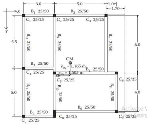
2:Discuss the suitability for earthquake resistance of the moment resisting framing plan of a three-storey building depicted here (cross-sectional dimensions in cm), the eccentricity of the centre of mass (as centroid of floor plan) to the centre of stiffness (from the moments of inertia of the columns) are shown. Suggest an alternative. Also, is there torsional flexibility? Are the two fundamental translational modes of vibration larger than the fundamental torsional mode of vibration. Discuss qualitatively.
Solution :
1. In seismic zones, frames are important in structural system. The location of frames in pan and their span lengths are normally governed by architectural and functional considerations, while beam depths may be controlled by design for factored gravity or seismic loads. Any single plane frame should run continous from one side of the building plan to the other without offsets and interruptions. Example indirect supports of beams on other beams. This causes large uncertainity concerning its rotational restaint by the supporting beam via torsion in the latter. Beam is less effective in frame action than one connected to columns at both ends. In the plan beam B7, B3 undergoes similar condition.
2. Beams and columns are in constant size in the given which is ideal for plane frame. Therefore no resize of beams and columns necessary
3. Beams doesnt continue straight from span to span but its axis is offset at the column between them, there is no smooth flow of beam internal forces through a proper beam-column joint, neither continuity of the beam longitudinal bars across the column from one span to the next. These bars have to terminate there and be separately anchored at the joint. Similar case is seen in the above plan, beams B5, B6 and B7, B8 should be continues instead.
4. Even when the beam axis is not offset from span to span, the smooth flow of internal forces from the beam to the column is impaired by a large eccentricity between the axis of beam and the supporting column. For that reason, an upperlimit is set on the eccentricity between the axis of the beam and column at their connection : e<bc/4 where bc is the largest crosssection of the column at right angles to the beam axis.
5. Torsional flexibility is less as structure is not perfectly symmetrical.
6. Since above plan is eccentric structure (center of mass doesnt coincides with center of rigidity) and two fundamental translational modes of vibration larger than the fundamental torsional mode of vibration if shear walls (stiff vertical elements) are placed at periphery.
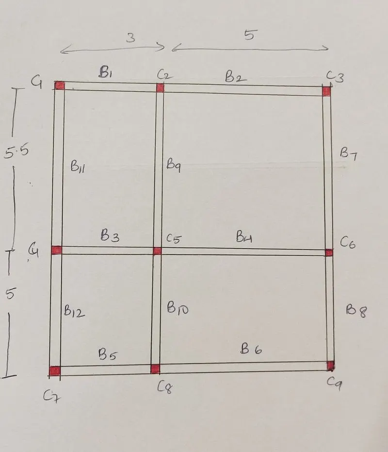
Alternative plan :
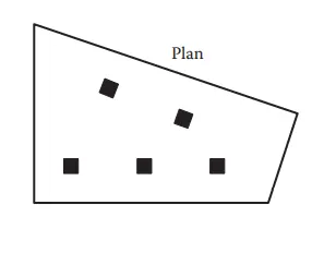
3:A multi-storey building with basement, with a quadrilateral (non symmetrical floor plan) plan as, has interior columns in an irregular (not in a grid) pattern in plan that serves architectural and functional considerations. Partition walls and interior beams supporting the slab have different layout in different stories. However, there is no constraint to the type, location and size of the lateral force resisting components and sub-systems on the perimeter. Proposals are to be made and justified for the choice of the lateral-load-resisting system and its foundation.
Solution :
1. Even though center of mass and center of rigidity doesnot coincide, maintaing stable eccentricity which s with limits ensures stability of the structure.
2. Providing rectangular shear walls at the periphery to avoid torsional irregularity.
3. Diaphragm should be rigid in the structure.
4. Individual footings are placed at the same level and interconnected through tie beams ensures less displacements.