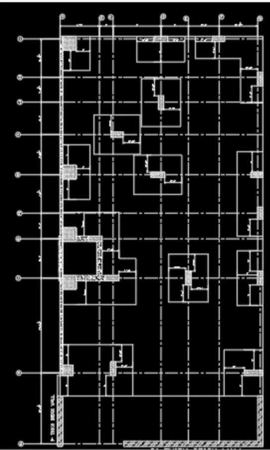
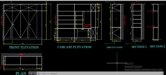
Creating a Wardrobe detailed drawing, Floor Plan, Kitchen Layout and Column Detail using AutoCad
Aim: To draft the Cabinet using AutoCAD
Commands used:
• LINE
• OFFSET
• TRIM
• ERASE
• MLEADER
• DIMLINEAR
• TEXT
• CIRCLE
• ERASE
Procedure:
1.Open AutoCad
2. Selecting metric system
3. Command UN(units) and selecting decimals with precision of O
4. Command LIMITS and having limit of (0,0) in lower left corner and
(10000,10000) in upper right corner
5. Command ZOOM and selecting All
Drawing Front Elevation
1. Command LINE and drawing a line of 2800mm horizontal and 2600mm vertical on four sides
2. Command OFFSET and offsetting 12 mm on left side and top side of cabinet
3. Command TRIM and trimming the unwanted lines
4. Command OFFSET and offsetting 100 mm from the bottom line of cabinet
5. Command OFFSET and offsetting 1223 from left offsetted line 6. Command OFFSET and offsetting 1200 from offsetted line
7. Command OFFSET and offsetting 365 from offsetted line
8. Command OFFSET and offsetting 500 mm from the top line of cabinet
9. Keeping Object snap ON and turning midpoint on through out its length
11. Command LINE and Drawing a line from midpoint of middle cabinet through out its length
12. Command OFFSET and offsetting 100mm slightly below the centre line of left sided divider and drawing vertical line
13. Command OFFSET and offsetting 100mm slightly below the centre line of middle cabinet divider and drawing vertical line
14. Command LINE and drawing a horizontal line of 50mm from midpoint of left sided divider and middle cabinet divider
15. Command CIRCLE and drawing a circle of 25mm from the point which line is drawn on both left sided divider and middle cabinet divider
16. Command ERASE and Erase the unwanted lines
17. Command TRIM and trim the unwanted lines
18. Command LINE and keeping ortho off draw a cross lines for each cabinet both for bigger and smaller cabinet
19. Command MLEADER and multileader style manager and modify in leader structure selecting maximum leader points as 3 and specfying points and type Section 1
20. Command TEXT and angle 90 degree and typing as wall structure
21. Command DIMLINEAR and dimensioning the Cabinet
Drawing Carcase Elevation
• Command LINE and drawing a line of 2800mm horizontal and 2600mm vertical on four sides
• Command OFFSET and offsetting 12 mm on left side and top side of cabinet
• Command TRIM and trimming the unwanted lines
• Command OFFSET and offsetting 100 mm from the bottom line of cabinet
• Command OFFSET and offsetting 720 mm from the 100mm offsetted line of cabinet
• Command OFFSET and offsetting 20 mm from the 720mm offsetted line of cabinet both from top and bottom
Command OFFSET and offsetting 12 mm and 300mm for the chamber respectively for 4 times
• Command OFFSET and offsetting 1223mm from left offsetted line from centerline
• Command OFFSET and offsetting 1200mm from offsetted line from centerline
• Command OFFSET and offsetting 365mm from offsetted line
• Command OFFSET and offsetting 900mm for 365mm portion
• Command OFFSET and offsetting 1180mm from 900mm line
• Command OFFSET and offsetting 12mm in the specified places
• For Stand OFFSET 400mm from the centerline of the left cabinet and offsetting for 50mm each on both sides
• Command LINE and keeping ortho off draw a cross lines for each cabinet for 365mm cabinet
• Command TEXT with height 50 and angle O type L.P, HANGER SPACE and 123 in specified place angle O type L.P, HANGER SPACE and 123 in specified place
• Command TRIM and trim the unwanted lines
• Command TEXT and angle 90 degree and typing as wall structure
• Command DIMLINEAR and dimensioning the Cabinet
Drawing Side Elevation
• Command XLine to Horizontal of baseline on top and bottom
• Command OFFSET of 100mm from the baseline
• Command OFFSET of 900mm from the baseline
• Command OFFSET of 1180mm from the 900mm line
• Command OFFSET of 20mm below the 900mm line
• Command OFFSET of 12mm on left, right and top edge of cabinet
• Command LINE and keeping ortho off draw a cross lines for each cabinet both for top and bottom cabinet
• Command HATCH and selecting the ANS131 selecting the outer portion of the section 2
• Command MLEADER and multileader style manager and modify in leader structure selecting maximum leader points as 3 and specfying points and type Section 2
• Command TEXT and angle 90 degree and typing as wall structure
• Command DIMLINEAR and dimensioning the Cabinet
• Command TEXT and angle O degree and typing as SIDE ELEVATION Command TRIM and trim the unwanted lines
Drawing Section 1
• Command Line to Horizontal of baseline on top and bottom
• Command OFFSET of 100mm from the baseline
• Command OFFSET of 900mm from the baseline
• Command OFFSET of 1180mm from the 900mm line
• Command OFFSET of 20mm below the 900mm line
• Command OFFSET of 12mm on left, right and top edge of cabinet
• Command OFFSET of 12mm and 300mm from 900mm line respectively for 4 times
Command HATCH and selecting the ANS131 selecting the outer portion of the section 1
• Command ARC and selecting Start, center and end draw a arc on top left corner
• Select Arc properties and change the colour to red
• Command DIMLINEAR and dimensioning the Cabinet
• Command TEXT and angle O degree and typing as Section 1
Command TRIM and trim the unwanted lines
Drawing Section 2
• Command XLine to Horizontal of baseline on top and bottom
• Command OFFSET of 100mm from Drawing Section 2
• Command XLine to Horizontal of baseline on top and bottom
• Command OFFSET of 100mm from the baseline
• Command OFFSET of 900mm from the baseline
• Command OFFSET of 1180mm from the 900mm line
• Command OFFSET of 20mm below the 900mm line
• Command OFFSET of 12mm on left, right and top edge of cabinet
• Command OFFSET of 365mm from the left line
• Select Arc properties and change the colour to red and place in specified place
• Command DIMLINEAR and dimensioning the Cabinet
• Command TEXT and type Detail-C and Detail-B
• Command TEXT and angle O degree and typing as Section 2
Drawing Plan
• Command XLine to Vertical of the Front elevation on both sides and on each chamber
• Command OFFSET 630mm
• Command OFFSET 2435mm
• Command OFFSET 365mm
Command OFFSET 12mm on 4 sides and on each chamber
• Command TRIM and trim the unwanted lines
• Select Arc properties and change the colour to red
• Command DIMLINEAR and dimensioning the Cabinet
• Command TEXT and angle O degree and typing as PLAN
Command TEXT and angle O degree and typing as Wall surface
• Command HATCH and selecting the ANS131 selecting the outer portion of the plan
• Command TEXT and angle 0 degree and typing as Wall surface
Adding Layer to the Drawing
• Command LAYER and adding
Dimensions and giving yellow colour
• Command LAYER and adding Heading texts and giving cyan colour
• Command LAYER and adding Leader texts and giving green colour
• Command LAYER and adding Texts and giving Red colour
Adding the Specified dimensions and texts to the specified layer respectively
RESULT:
FLOOR PLAN
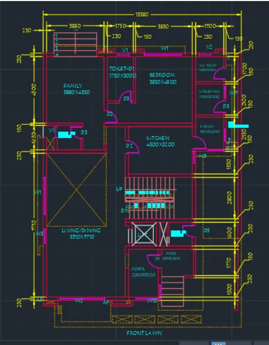
Aim: To draft the floor plan of the house and dimensioning it using AutoCAD
Procedure:
-Open AutoCad
-Selecting metric system
-Command UN(units) and selecting decimals with precision of O
-Command LIMITS and having limit of (0,0) in lower left corner and (10000,10000) in upper right corner
-Command ZOOM and selecting All
Commands used:
XLINE
• XLINE horizontal and vertical is used to start the drawing initally
LINE
• LINE is used to draw the line in the Window, Doors, Ventilators, Staircase and lines at required spaces
OFFSET
• OFFSET is used to offset the external walls to 230mm and internal walls to 150mm
• OFFSET is used to offset the Living/Dining room to 5310mm horizontal and 9710mm vertical
• OFFSET is used to offset the Power RM to 1800mm horizontal and 1650mm vertical
• OFFSET is used to offset the Family to 3880mm horizontal and 4350 vertical
• OFFSET is used to offset the Toilet-01 to 1750 horizontal and 3000 vertical
• OFFSET is used to offset the Bedroom-01 to 3830 horizontal and 4500 vertical
• OFFSET is used to offset the Kitchen to 4300 horizontal and 3200 vertical
• OFFSET is used to offset the Lumber RM to 1570 horizontal and 1600 vertical
• OFFSET is used to offset the Patio to 2150 horizontal and 2100 vertical
• OFFSET is used to offset the Foyer to 2000 horizontal and 3220 vertical
• OFFSET is used to offset the Utility to 1900 horizontal and 2150 vertical
• OFFSET is used to offset the Utility RM to 1900 horizontal and 2100 vertical
OFFSET is used to offset the D.H Toilet to 1900 horizontal and 1700 vertical
• OFFSET is used to offset the different lines to specified offsetting distance
PLINE
PLINE is used to draw the Front Lawn points and Chejjas above the windows and ventilators
RECTANGLE
• RECTANGLE is used to draw the Side Table, TV Units, Sofa Sets in Family Room
• RECTANGLE is used to draw the Shelf, Service Trolley, Carpet, Sofasets and Dining Table in Living/Dining Room
• RECTANGLE is used to draw the Lift
• RECTANGLE is used to draw the Working Platform-1 and 2 in Kitchen
RECTANGLE is used to draw the Dishwasher and W/M Dryer in the Utility
• RECTANGLE is used to draw the Bed,Dressing Wardrobe and Pillow in Bedroom
TRIM
• TRIM is used to trim the unwanted lines
CIRCLE
• CIRCLE is used to draw the Planter, Dining Table Seats, Chandelier and Outdoor Seating
ARC
• ARC is used to draw the doors with Start, Center and End
LINETYPE
• LINETYPE is to change the Continuous line to Dash line and changing the scale to 20
ELLIPSE
ELLIPSE is used to draw the Center Table with specifying the minor axis horizontal and drawing to specified length
LAYER
• LAYER is used to layer different components of Building to different layer
Annotate Tab
• In Annotate Tab ---->Modify dimension style---->Text and Style
-Changing the style from ISO25 to Comic San----> Set current----- >Apply
TEXT
• TEXT is used to write the name of the furniture and electronic items at the specified location
• TEXT is used to write the dimensions and names of the different rooms
ERASE
• ERASE is used to erase the unwanted lines which cannot be trimmed using Trim Command
RESULT:
KITCHEN PLAN
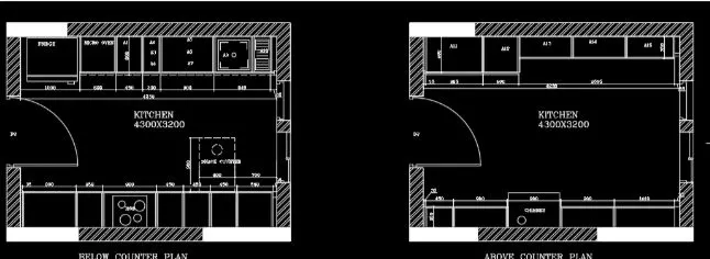
Aim: To draft the floor plan of the house and dimensioning it using AutoCAD
Procedure:
-Open AutoCad
-Selecting metric system
- Command UN(units) and selecting decimals with precision of O
- Command LIMITS and having limit of (0,0) in lower left corner and (10000,10000) in upper right corner
- Command ZOOM and selecting All
Commands used:
XLINE
• XLINE horizontal and vertical is used to start the drawing initally
LINE
• LINE is used to draw the line in the Window and Doors at required spaces
OFFSET
Sketching below counter plan
• OFFSET is used to offset the external walls to 230mm
• OFFSET is used to offset the Working platform 1 for 1000, 600, 450, 300, 900, 945 and 35 respectively in horizontal direction
• OFFSET is used to offset the Working platform 1 for 600mm vertically
• OFFSET is used to offset the Working platform 2 for 35, 900, 450, 900, 450, 450, 450, 560 and 35 respectively in horizontal direction
• OFFSET is used to offset the Working platform 2 for 600mm vertically
• OFFSET is used to offset the 700 mm from right wall horizontally and 900 mm vertically for snack counter
• OFFSET is used to offset 12mm on both sides to the main offsetted line to dimension it center to center
Sketching above counter plan
• OFFSET is used to offset the external walls to 230mm
• OFFSET is used to offset the Working platform 1 for 35, 965, 600, 2595 and 35 respectively in horizontal direction
• OFFSET is used to offset the Working platform 1 for 600 and 350 mm in vertical direction
• OFFSET is used to offset the Working platform 2 for 35, 450, 900, 900, 900, 1010 and 35 respectively in horizontal direction
• OFFSET is used to offset the Working platform 2 for 350mm in vertical direction
• OFFSET is used to offset 12mm on both sides to the main offsetted line to dimension it center to center
PLINE
• PLINE is used to draw the fridge, Micro oven, Hob, sink and Chimney both in below and above counter plan
DDptype
Changing the points to visible points to divide the line
DIVIDE
Dividing the 2595 line into 3 equal parts
DIMBREAK
• DIMBREAK is used to break the dimensions which are crossing each other in snack counter 900mm dimension line is breaked from 450mm line
TRIM
• TRIM is used to trim the unwanted
lines
CIRCLE
• CIRCLE is used to draw the Sink hole, Snack counter ,hob and Chimney
ARC
• ARC is used to draw the doors with Start, Center and End
LINETYPE
• LINETYPE is to change the
Continuous line to Dash line and changing the scale to 20
Annotate Tab
• In Annotate Tab ---->Modify dimension style---->Text and Style
Changing the style from ISO25 to Romanc.shx----> Set current-->Apply
DIMLINEAR
• DIMLINEAR is used to dimension the working platform 1 and 2
DIMCONTINUE
DIMCONTINUE is used to dimension quickly using after DIMLNEAR command for working platforms
TEXT
• TEXT is used to write the name of the electronic items at the specified location like Fridge, Micro oven etc
• TEXT is used to write the dimensions of different compartment like A1 to A15
ERASE
• ERASE is used to erase the unwanted lines which cannot be trimmed using Trim Command
RESULT:
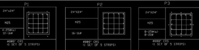
COLUMN SCHEDULE
Aim: To Schedule the column using AutoCAD
Procedure:
-Open AutoCad
-Selecting imperial system
-Command UN(units) and selecting Engineering with precision of O'-0"
-Command LIMITS and having limit of (0,0) in lower left corner and (100,100') in upper right corner
-Command ZOOM and selecting All
Commands Used
• LINE
• OFFSET
• TRIM
• DDPTYPE
• DIVIDE
• CIRCLE
• FILLET
• LWEIGHT
• SCALE
Drawing the column:
1. Type Command LINE and draw 24" horizontal line and 24" vertical line on both the sides
2. Type Command OFFSET and draw an offset of 1" on all 4 sides
3. Type Command TRIM and trim the unwanted lines
4. Type Command DDPTYPE and select suitable point type
5. Type Command DIVIDE and divide the line into 4 segments on 24" of both sides
6. Type Command CIRCLE of diameter of 25mm=1" of 4 numbers at 4 corners
7. Type Command CIRCLE of diameter of 16mm=0.62" of 12 numbers at remaining place
8. Type Command FILLET of radius of 1" at 4 corners
9. Type Command TEXT of height 8" and style of Roman.shx and angle of O degree and type 24"/24", M25, 425dial type %%C for diameter symbol), 12-16 dia(type %%C for diameter symbol), (type %%C for diameter symbol)8@8" CRS (1 SET OF 5 STRIPS)
10. Command LWEIGHT and draw a stirups of 8mm dia at the required places
11. Command SCALE and scale the texts and diagram
12. Command LINE and draw a line like table and place the texts and diagram in suitable places.
RESULT:
RAFT FOUNDATION PLAN
Aim: To draft the Raft foundation and dimensioning it using AutoCAD
Procedure:
-Open AutoCad
-Selecting Imperial system
-Command UN(units) and selecting Architectural with precision of O'-1/256"
-Command LIMITS and having limit of (0,0) in lower left corner and (1000;1000') in upper right corner
-Command ZOOM and selecting All
Commands used:
XLINE
• XLINE horizontal and vertical is used to start the drawing initally
OFFSET
• OFFSET is used to offset the XLINE horizontal 5'-7.5"
• OFFSET is used to offset the 5'-7.5" to 3'-7.5"
• OFFSET is used to offset the 3'-7.5" to 4'-9"
• OFFSET is used to offset the 4'-9" to 5'-10.5"
• OFFSET is used to offset the 5'-10.5" to 5'-7.5"
• OFFSET is used to offset the 5'-7.5" to 3'-9"
• OFFSET is used to offset the 3'-9" to 5'-9"
• OFFSET is used to offset the 5'-9" to 13-10.5"
• OFFSET is used to offset the 13'-10.5" to 10'-4.5"
• OFFSET is used to offset the XLINE vertical 5'-9"
• OFFSET is used to offset the 5'-9" to 2'
• OFFSET is used to offset the 2' to 7"
• OFFSET is used to offset the 7' to 4'
• OFFSET is used to offset the 4' to 4'-6"
• OFFSET is used to offset the 4'-6" to 5'-7.5"
• OFFSET is used to offset the 5'-7.5" to 9" thick wall
• OFFSET is used to offset the foundations to 3',2'-6" and 2 respectively
TRIM
•TRIM is used to trim the unwanted lines
FILLET
• FILLET is fillet the offsetted foundation concrete distance with radius O
PLINE
• PLINE is used to draw the foundation of 24"x24", 9"x24",9"x21" and 9"x30" respectively
MLEADERSTYLE
• MLEADERSTYLE-----> content----> mleader type-----> Block----> source block---->circle
MLEADER
• MLEADER is used to leader the horizontal lines as 1 to 8 • MLEADER is used to leader the
vertical lines as A,B,C,D,E,F and G
LINETYPE
• LINETYPE is to change the Continuous line to ISO long dash short dash line and changing the scale to 10
DIMLINEAR
• DIMLINEAR is used to dimension the offsetted line
DIMCONTINUE
DIMCONTINUE is used to dimension quickly using after DIMLINEAR command for offsetted line
HATCH
• HATCH is used to hatch the foundation to ANS137 for 24"x24", 9"x24",9"x21" and 9"x30"
• HATCH is used to hatch the concrete portion to AR-CONC
• HATCH is used to hatch the 9" thick brick wall to ANS132
TEXT
• TEXT is used to write the 9" thick brick wall With height 2" and O angle
• TEXT is used to write the Raft Foundation PLan with height 3" and O angle
ERASE
ERASE is used to erase the unwanted lines which cannot be trimmed using Trim Command
RESULT: