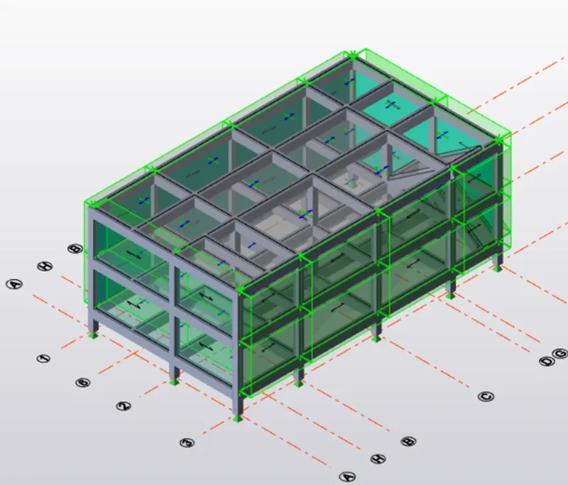
To calculate the dead , live and wind load for RC residential structure and to apply them using TSD
1)
Aim - To calculate the Dead load as per IS code specifications
Assume - External wall thickness = 230mm
Internal wall thickness = 150mm
Finishes = 50mm
Calculations -
Dead load due to floor finishes -
Unit weight of material= 24 kn/m^3
Dead load = 0.05*24 = 1.2 Kn/m^2
Unit weight of Brick = 20 Kn/m^3
Height of floor level = 3.5m
Dead load of external wall = 0.23*3.5*20 = 16.1Kn/m^2
Dead load of Internal wall = 0.15*3.5*20 = 10.5 Kn/m^2
Dead load of Roof = 1.5 Kn/m^2
Procedure -
- Open the Tekla Challenge 8 file
- Select Loadcases in Load tab
- Add the loadcases in dialogue box
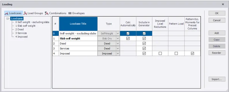
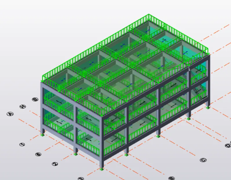
- Floor finishes and Brick wall load are applied to each floor
- First select the floor where we want to apply the load
- Select Dead load from left bottom corner of load case
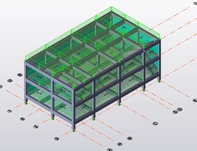
- In load tool bar select Area option and edit the load value and apply the load in Global Z direction
- Apply Roof load as 1.5 Kn/m^2
- Finishes load as 1.2 Kn/m^2
- Apply the Brick wall load using Area option from load tool bar and apply the load
- External Brickwall load as 16.1 Kn/m^2
- Internal Brickwall load as 10.5 Kn/m^2
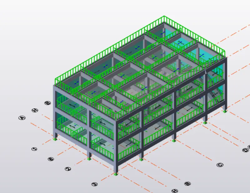
Result - Dead load and Brickwall load are applied
2)
Aim - To calculate Live load as per IS code specifications
Procedure -
- Office Room = 2 Kn/m^2
- Toilets = 2 Kn/m^2
- Common Area = 3 Kn/m^2
- Staircase = 3 Kn/m^2
- Conference Room = 5 Kn/m^2
- Select each floor and apply the live load
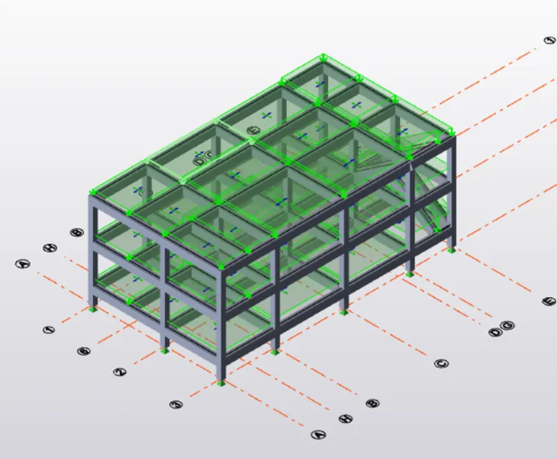
- Live load is applied on staircase
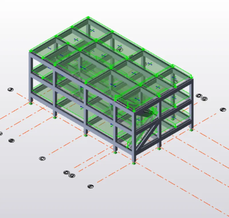
Result - Live load are applied to each floor
3)
Aim - To Generate manual wind loading in the design report based on IS code
Calculations -
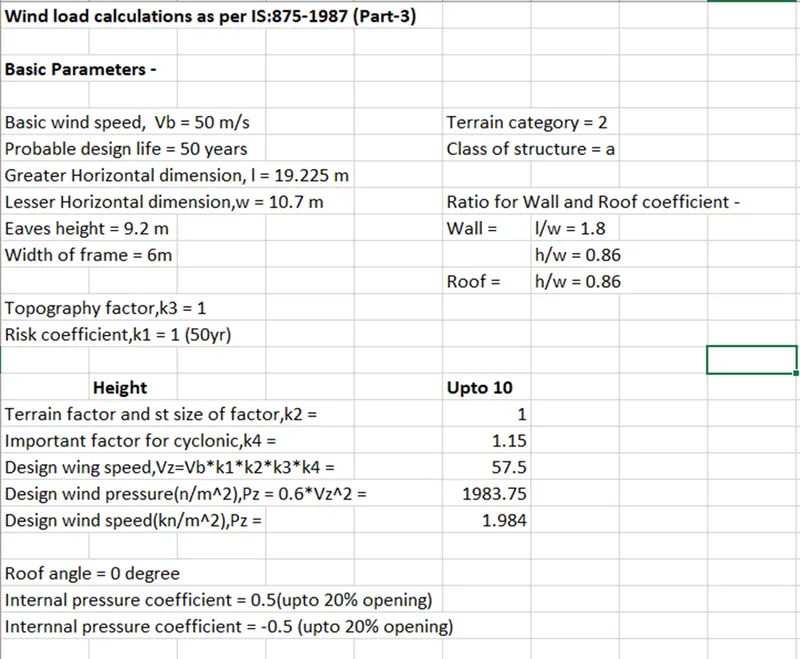
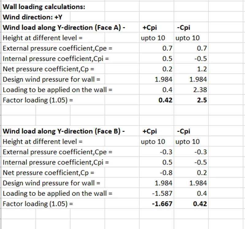
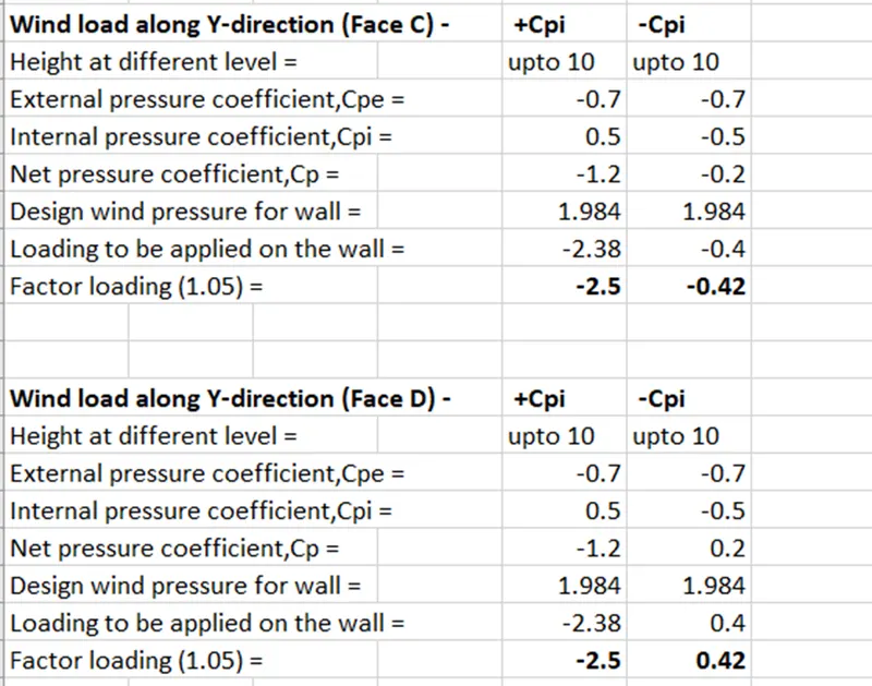
- Wind load calculations along Y direction -
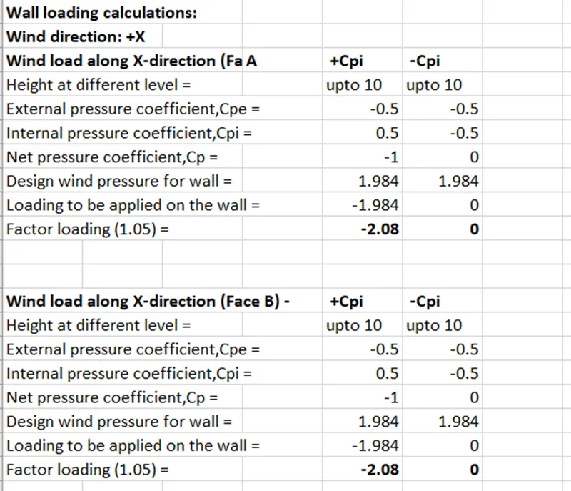
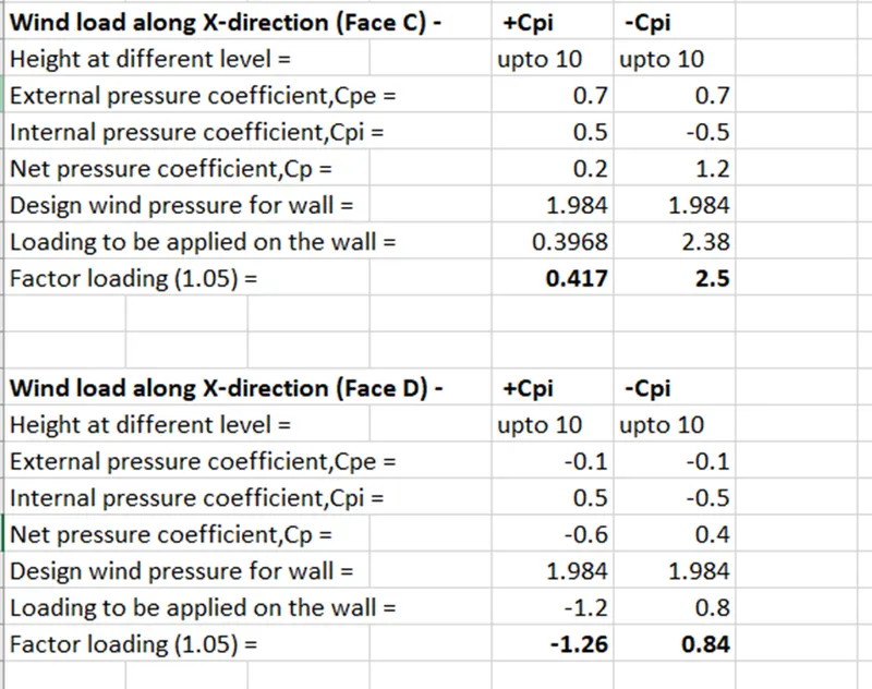
- Wind load calculations along X direction -
4)
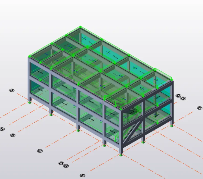
Aim - To apply the Wind load calculations on the model
Procedure -
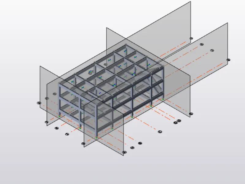
- In the model tab select frames and create a frames as frame 1,frame 3,frame E,frame A
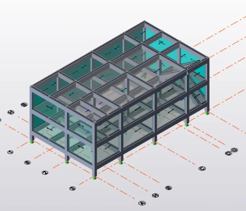
- Using Model tab draw wall panels
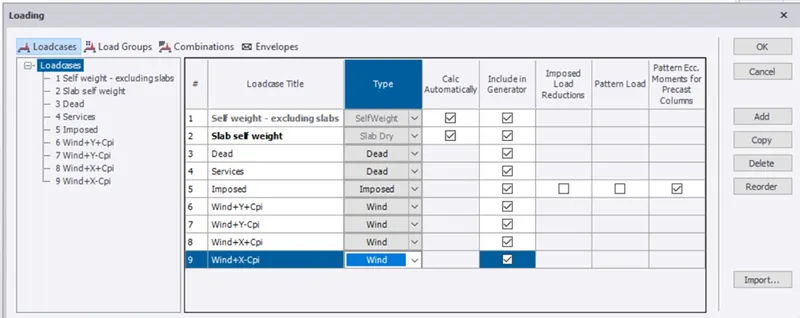
- Under load tab create loadcases ,add new loadcases as wind+y+cpi, wind+y-cpi, wind+x+cpi, wind+x-cpi and select type as wind then click OK
Wind load in Y - direction -
- Select Frame 3 as Face A and apply wind load = wind+y+cpi= 0.42kn/m^2 and wind+y-cpi= 2.5kn/m^2 along Global y direction using Area option
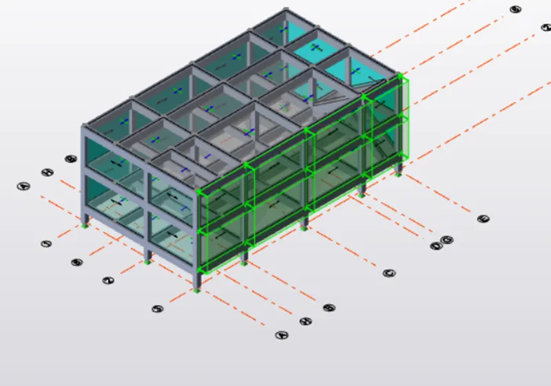
- Select Frame 1 as Face B and apply wind load = wind+y+cpi= -1.667kn/m^2 and wind+y-cpi= 0.42kn/m^2 along Global y direction using Area option
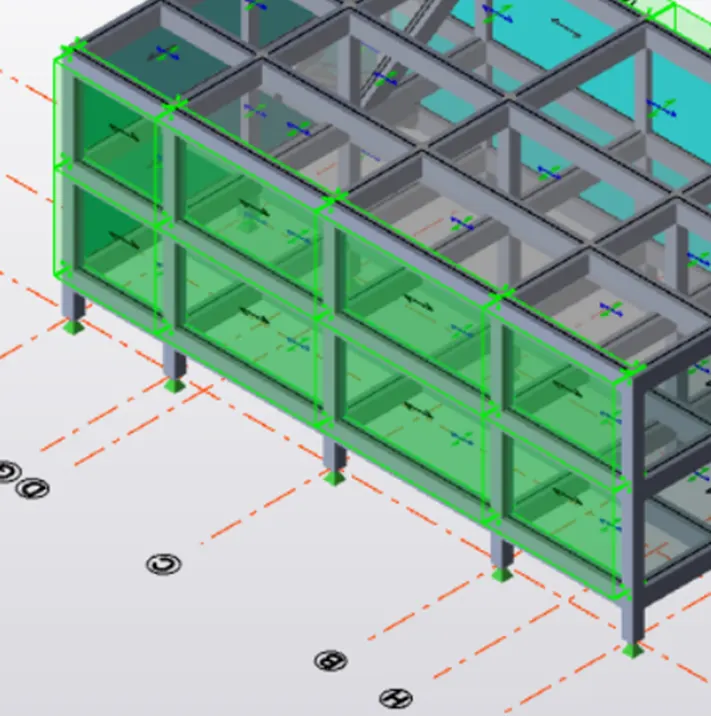
- Select Frame A as Face C and apply wind load = wind+y+cpi= -2.5kn/m^2 and wind+y-cpi= 0.42kn/m^2 along Global x direction using Area option
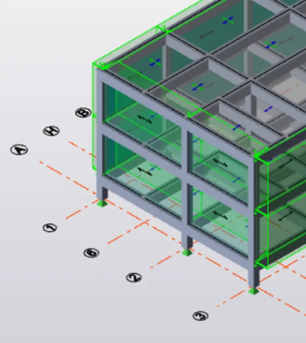
- Select Frame E as Face D and apply wind load = wind+y+cpi= -2.5kn/m^2 and wind+y-cpi= 0.42kn/m^2 along Global x direction using Area option
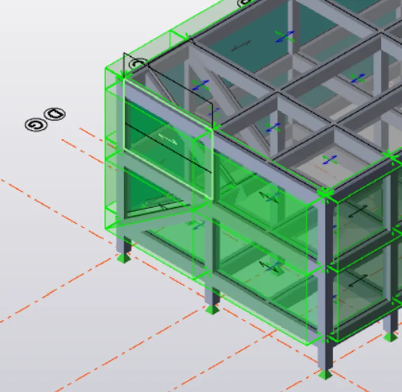
- 3d view - wind+y-cpi
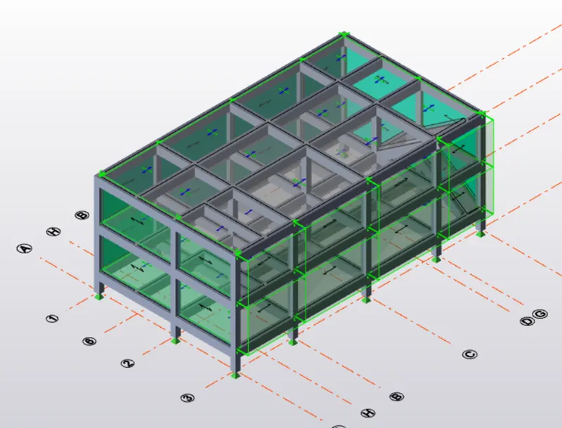
Wind load in X direction -
- Select Frame 3 as Face A and apply wind load = wind+y+cpi= -2.08kn/m^2 and wind+y-cpi= 0 kn/m^2 along Global y direction using Area option
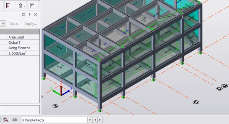
- Select Frame 1 as Face B and apply wind load = wind+y+cpi= -2.08kn/m^2 and wind+y-cpi= 0 kn/m^2 along Global y direction using Area option
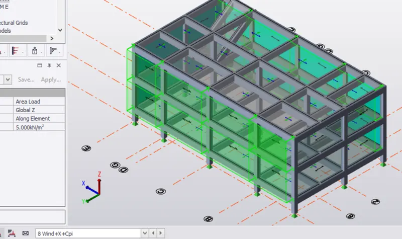
- Select Frame A as Face C and apply wind load = wind+y+cpi= 0.417 kn/m^2 and wind+y-cpi= 2.5 kn/m^2 along Global x direction using Area option
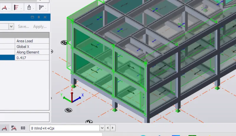
- Select Frame E as Face D and apply wind load = wind+y+cpi= -1.26 kn/m^2 and wind+y-cpi= 0.84kn/m^2 along Global x direction using Area option
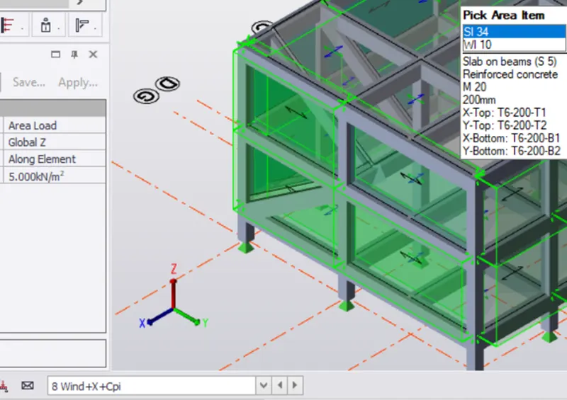
Result - Wind load are applied to each frame