AutoCAD_Footing Detailing, Floor Plan and Isometric View_Week 2
AIM: To draw the given sketches in Autocad.
INTRODUCTION: Autocad offers commands like Offset,Move,Copy,Rotate,Mirror etc for ease of drawing sketches.
PROCEDURE:
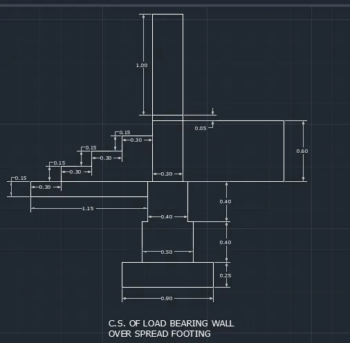
- C1:
- Use the Line command.
- Initial point at (10,0)
- 2nd point: @0.25<90
- 3rd point @0.2<0
- 4th point: @0.4<90
- 5th point: @0.05<0
- 6th point @0.4<90
- 7th point: @0.05<0
- 8th point @165<90
- 9th point: 0.3<0
- 10th pointi @1.65<270
- 11th point @0.05<0
- 12th point @0.4<270
- 13th point: @0.05<0
- 14th point: @0.4<270
- 15th point @0.2<0
- 16th point: @0.25<270 and close
- 17th point: From 7th point @1.15<180
- 18th point: @0.15<270
- 19th point @0.15<0
- 20th point From 17th point @0.3<0
- 21th point @0.15<90
- 22nd point @0.330
- 23rd point: @0.15<90
- 24th point: @0.3<0
- 25th point: @0.15<90
- 26th point: @0.3<0
- 27th point: From 10th point @1<0
- 28th point: @0.6<90
- 29th point: @1<180
- Command offset offsetting the top 0.3m line to a distance of 1m and 1.05m.
2.C2:
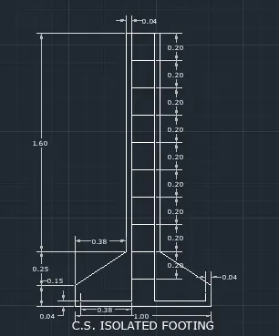
- initial point (0,0)
- 2nd point: @0.15<90
- 3rd point: @0.455<33.341
- 4th point: @1.60<90
- 5th point: @0.24<0
- 6th point @1.60<270
- 7th point: @0.455<326.659
- 8th point: @0.15<270 and close
- Offsetting 1m line at a distance of 0.04m using offset command
- offsetting 1.60m line at a distance of 0.04m
- offsetting 0.16m line at a distance of 0.2m for 9 times.
3. C3:
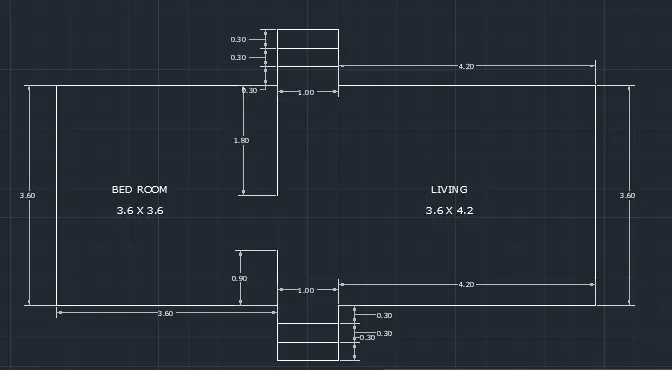
- Initial point at (20,0)
- 2nd point: @3.60<90
- 3rd point: @3.60<0
- 4th point: @0.9<90
- 5th point: @1<0
- 6th point: @0.9<270
- 7th point: @4.2<0
- 8th point: @3.6<270
- 9th point: @4.2<180
- 10th point: @0.9<270
- 11th point: @1<180
- 12th point: @0.9<90
- 13th point: @3.60<180
- 14th point From 3rd point @1.80<270
- 15th point: From 12th point @0.9<90
- Command offset: 1m line at a distance of 0.3m two times both in top and bottom.
4.C4:
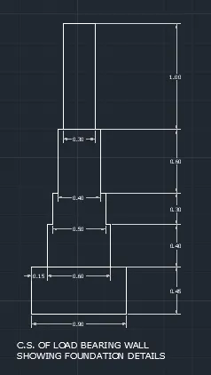
- Initial point at (4,4)
- 2nd point: @0.45<90
- 3rd point: @0.15<0
- 4th point @0.4<90
- 5th point: @0.05<0
- 6th point: @0.3<90
- 7th point: @0.05<0
- 8th point: @0.6<90
- 9th point: @0.05<0
- 10th point @1<90
- 11th point @0.3<0
- 12th point @1<270
- 13th point: @0.05<0
- 14th point @0.6<270
- 15th point: @0.05<0
- 16th point: @0.3<270
- 17th point @0.05<0
- 18th point @0.4<270
- 19th point @0.15<0
- 20th point @0.45<270 and close
- Join the 0.9m and 0.4m line.
5. C5:
- In snap settings, select isometric snap.
- Toggle appropriately between Isoplane left, isoplane top and isoplane right.
- Keep the ortho mode on.
- Isoplane right: Command line of length of 0.15m and 0.3m for 5 times.
- Isoplane left: Command line of length 1m both sides.
- Isoplane right: command line of length 0.15m and 0.3m both for five times and join the lines.
- For waist slab from bottom edge in isoplane top a line of 0.3m and top edge in isoplane right a line of 0.15m and join it.
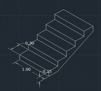
6.C6:
- In snap settings, select Isometric snap.
- Toggle appropriately between Isoplane left, isoplane top and isoplane right.
- Keep the ortho mode on.
- Command line selecting a random point
- Isoplane right: 3m,1m,2.42m,1m,2.42m,1m 3m in correct directions.
- Isoplane left: From left 3m line 0.3m and 0.3m from top and bottom and join these lines.
- Draw a perpendicular line to the middle of gabble wall. With a bottom distance of 4m and join it in triangular form.
- Isoplane top: 0.3m from top triangular edge and 0.3m from top right corner and join it.
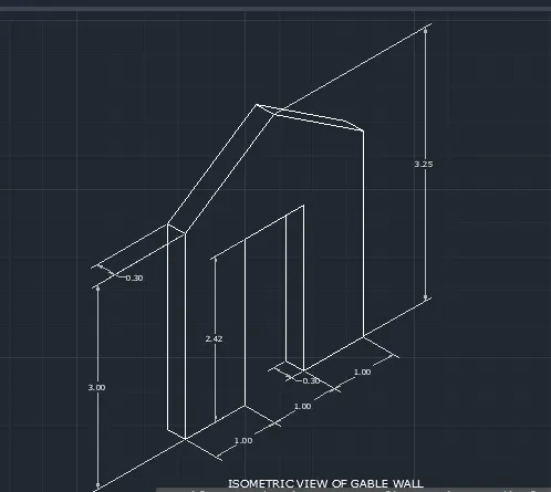
RESULT: The figures have been drawn using Autocad.