Week 8 Challenge
1.
Aim: To apply load exercise to member of the structure.
Given -
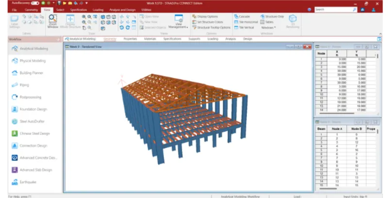
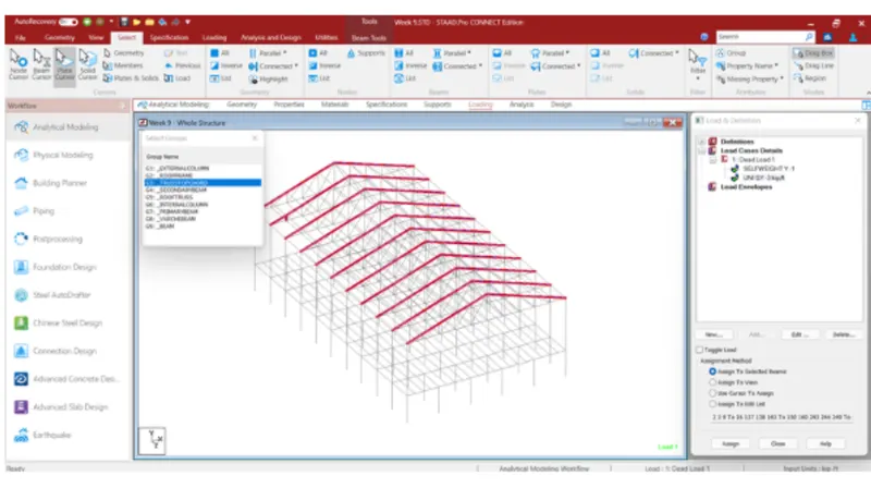
Form a Load case as DL for Dead Load.
Apply Self weight.
Apply member load of 3 kN/m on the rafter.
Apply member load of 6 kN/m on the secondary beams.
Apply point load of 20 kN at node intersecting inclined member on the top chord.
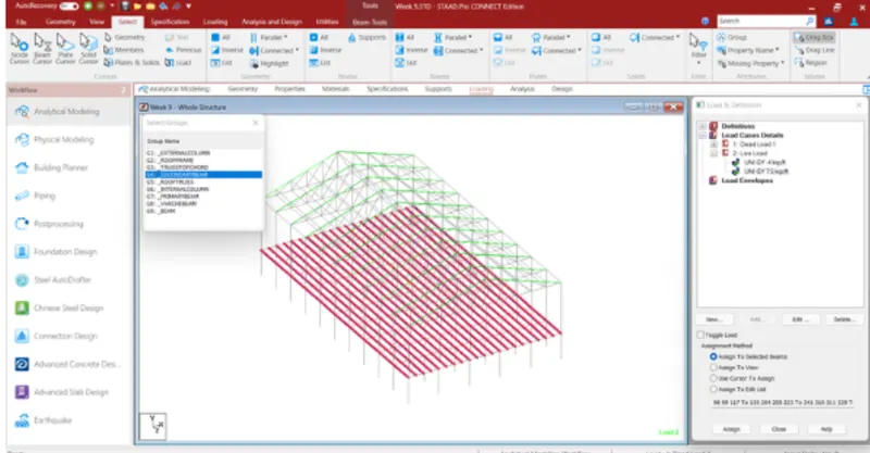
Form a Load case as LL for Live Load. Apply member load of 4 kN/m on the rafter.
Apply member load of 7.5 kN/m on the secondary beams.
Form load combination 1.5DL+1.5LL.
• Procedure -
• Go to loading option in that load case details.
• Add loads such as dead load, live load.
• In member load put loads as per given data. . Choose Y direction to apply loads. Negative sign acts as a downward direction.
Assign loads to selected member as per given data.
• For nodal load go to it add load at FY point.
• Assign load to selected nodal points.
• For load combination go to load combination option.
• Select dead load, live load and apply factor as per given data.
• Here we can take as servecibility criteria so add one additional load combination.
• 1DL+ILL.
• After that add load combination.
2.
• Aim - To run the analysis and find results on the member mentioned.
Given -
• Run the analysis.
. Find the Maximum Moment in the Secondary beam for 1.5DL+1.5LL case.
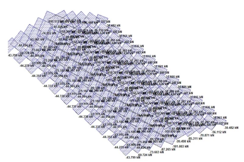
• Find the Maximum Axial force on the inclined bracing and identify the member having the maximum force for 1.5DL+1.5LL case.
• Identify Bottom chord of Truss having Maximum shear Force & Maximum moment for 1.5DL+1.5LL case and present the values.
• Maximum moment for secondary beam 1.5DL+ 1.5LL case - 53.343 KNm.
• Maximum axial force on inclined bracing - 456.949 KN.
• Member on which acts maximum force for 1.5DL+1.5LL case - Beam member no 13.
• Maximum shear force for bottom chord 260.262 KN.
• Maximum moment for bottom chord - 420.855 KNm.
• Member on which acts maximum shear force and maximum moment for 1.5DL+1.5LL case - Beam member no 1.
3.
Aim: To view and rectify the warnings and instabilities in the structure.
• Procedure -
Go to given attachment. Open the model of structure.
• After go run analysis option
• Choose perform analysis.
• Run the analysis.
• See the warning in view option.
• See the instability in the Results layout option. Choose that and fix it.
• After all warnings fixed we was run the analysis and see the result.
• Go to results view instability for the joint.
4.
Aim - To apply design parameters for modelled structure as per IS 800:2007 code.
Procedure -
• Go to analysis and design.
• Select steel as material. Select IS 800:2007 code.
• Define design parameters.
Apply it on beam and truss element.
• Here we take Lx - not applicable.
Ly - as a default use for apply to member.
• Lz - as a default use for aaply to member.
Ky - as factor take 1.2 as per IS 800.
• Kz - as factor take 1.2 as per IS 800.
• Other parameters such beam apply to selected as 1.0.
• Utility ratio as take 1.2 for apply to structure.