Project 1
Given -
Design only a Main Frame with Lean (Grid 2) & Gable Frame without Lean (Grid 15)
• Assume purlin load as 8.77 kg/m = 0.086 KN/m.
• Assume Gantry girder wt. = 158.24 kg/m = 1.55 KN/m.
• Assume Rail weight = 53 kg/m = 0.5179 KN/m.
Building Parameters: -
1
Building Width=30000.00 mm
Out to Out of Steel
2
Building Length
140000.00 mm
Center to Center of Steel Column
3
Building Height=11100.00 mm
Clear Height from FFL
4
Roof Slope=1:10
5
Column Base
Fixed Base
Assumed
To control Deflection
6
Bay Spacing (in mm)
Main frame with Rafters:14@10000
Center to Center of Steel Column
7
Roof Bracing
Diagonal Angle Bracing
8
Wall Bracing
Portal Bracing and above Angle Bracing
Up to 6.5m Portal Bracing
9
End Wall Type
Rigid Frame
Assumed
GENERAL PARAMETERS
Loads & Design
1. Dead Load=0.14 KN/m2
Assumed
2. Coil Load=0.15 KN/m2
False ceiling load for Roof extension alone
3. Live Load=0.75 KN/m2
Code:IS 875 (Part 2) -2015
4.Wind Load
Wind Speed=180 KMPH
Code:IS 875 (Part 3) - 2015
K1 =1.00
Code:IS 875
(50 years of mean probable design life)
K2 =0.94
Code:IS 875
(Terrain Category 3)
K3 =1.00
Code:IS 875
(Upwind slope is less than 3°)
K4 =1.15
Code:IS 875 (Cyclone Zone)
Building Condition
Medium Permeability
Code:IS 875 (Part 3) - 2015
5.Seismic Zone
Zone III
Code:IS 1893-2015 (Part 4)
6. Loads applied as per:IS 875 - 2015
7.Primary Member design
IS 800: 2007
8.Cold Form Design AISI 2001
Assumed
• Procdure:
A) For main frame and gable frame:
Open staad -> define nodes and beams as per given data -> Go to translation assign bay specing.
For Area 1 - 30 m width.
roof slope = 1/10 = 0.1.
Height of roof in top level = 1.5 m.
• Add walls -> Add wall sheeting -> add roof sheeting.
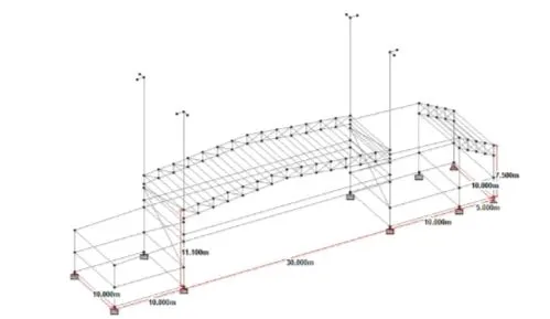
• Add properties -> go properties section database ->add and assign section to structure.
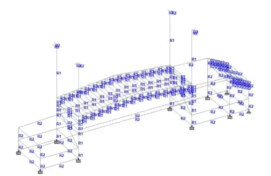
Go to support -> create support -> add and assign support -> fixed base and pinned base.
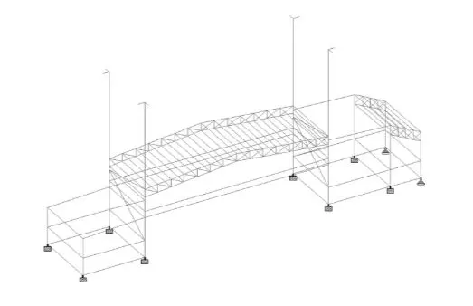
• Go to loading -> add load defination and load case details -> assign loads to
structure.
• Total D.L. =
4.5+ 1.5 +1.5 +0.75 = 8.25 KN/m.
• Total L.L. = 22.5+ 7.5 +3.75 + 7.5 = 41.25 KN/m.
• Total Coll load = 0.15 x 30 = 4.5 KN/m.
Total wind load =184 KMPH= 50 m/s.
• Internal pressure coefficiant = +/- 0.5.
• External pressure coefficient:
-0.9
-0.4
-0.8
-0.4
• As per given data
Design wind speed = Vb x k1 x k2 x k3 x k4.
= 50 x 1 x 0.94 x 1 x 1.15.
= 54.05 m/s.
• Wind pressure = 0.6 x 54.05^2.
• 1.75 KN/m^2.
• As per IS 875 Wind direction factor kd = 1
Area averaging factor ka = 0.83 .
• Combination factor kc = 0.9
Design wind pressure = 1.75 x 1 x 0.83 x0.9= 1.307 KN/m^2.
• Wind load = 1.307 x 11.1 = 14.50 KN/m.
• O+CPI = 14.50+ 0.5 0.9 = 14.10 KN/m.
• 14.50+ 0.5 -0.4 = 14.6 KN/m.
• O - CPI = 14.50 - c 0.5-0.9 .9=13 KN/m.
• 90 + CPl = 14.50 + 0.5 - 0.8 = 14KN / m .
• 9O - CPI = 14.50 - 0 -0.8=13.2 KN/m.
• 14.50-0.5 0.4 = 13.6 KN/m.
• Seismic load =
EQ + X.
EQ - x.
EQ + Z.
EQ - Z.
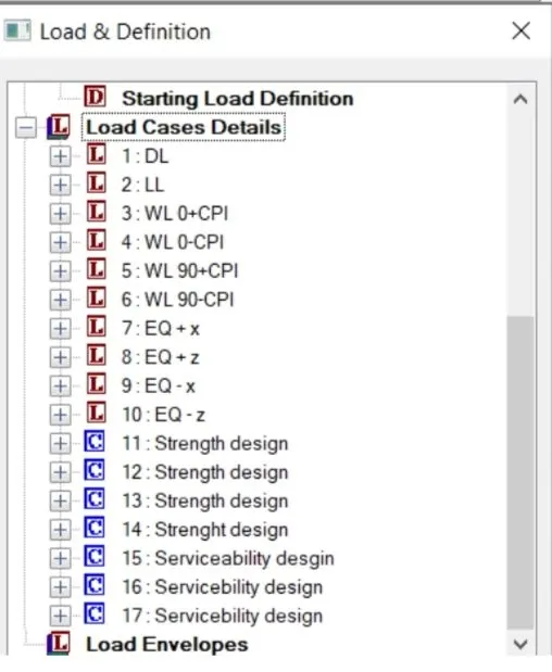
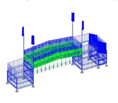
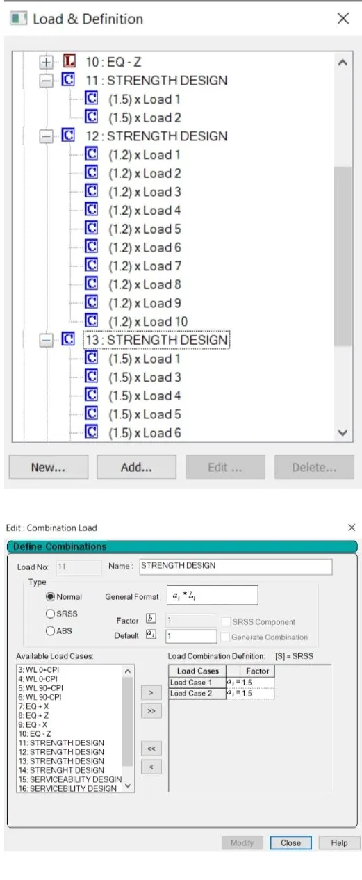
• Add load combinations -> go to load combination add as per strength design and servicebility criteria.
• Go to design -> add design parameters ->Use IS 800: 2007.
• After run analysis and check deflection and section safe results.
B) For gable frame and gable frame.
Open staad -> define nodes and beams as per given data -> Go to translation assign bay specing.
For gable frame we analysis and design for one frame.
• For Area 1 - 30 m width.
• roof slope - 1/10 = 0.1.
Height of roof in top level = 1.5 m.
Add walls -> Add wall sheeting -> add roof sheeting
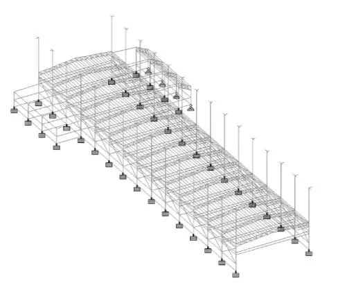
Add properties-> go properties section database ->add and assign section to structure.
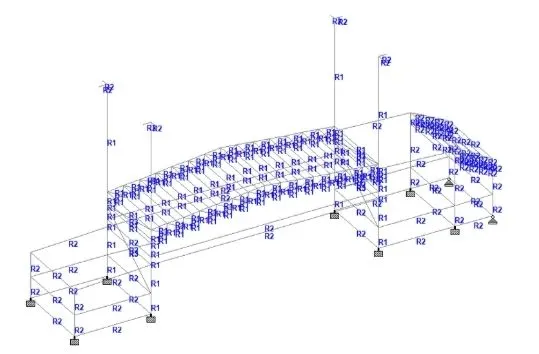
• Go to support -> create support -> add and assign support -> fixed base and pinned base.
• Go to loading -> add load defination and load case details -> assign loads to structure.
• Total D.L.=4.5+1.5+1.5+0.75=8.25 KN/m.
Total L.L.=22.5+7.5+3.75+7.5=41.25 KN/m.
• Total Coll load =0.15*30=4.5 KN/m .
• Total wind load = 184 KMPH = 50 m/s.
• Internal pressure coefficiant = +/- 0.5.
• External pressure coefficiant =
-0.9
-0.4
-0.8
-0.4
• Combination factor kc = 0.9 .
Design wind pressure = 1.75 x 1 x 0.83 x 0.9. • 14.50-0.5 -0.4 = 13.6 KN/m.
• 90-CPI = .5-0.8=13.2 KN/m.
As per given data
Design wind speed = Vb x k1 x k2 x k3 x k4.
= 50 x 1x 0.94 x 1 x 1.15.
= 54.05 m/s.
Wind pressure = 0.6 x 54.05^2= 1.75 KN/m^2.
• as per IS 875 Wind direction factor kd = 1
• Area averaging factor ka = 0.83 .
• 1.307 KN/m^2.
• Wind load = 1.307 x 11.1 = 14.50 KN/m.
• O+CPI = 14.50+ 0.5 0.9 = 14.10 KN/m.
• 14.50 + 0.5 0.4 = 14.6 KN/m.
• O - CPI = 14.50 0.5 0.9 = 13KN / m .
• 9O + CPI = 14.50 -0.8=14 KN/m.
= 14.50 +0.5 0.4 = 14.6 KN/m.
. = 14.50 - 0.5 -0.4 = 13.6 KN/m.
Seismic load =
• EQ + X.
• EQ - X.
• EQ + Z.
• EQ - Z.
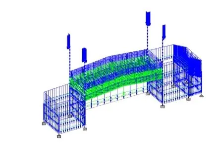
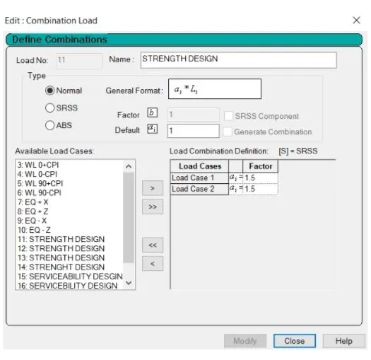
Add load combinations -> go to load combination add as per strength design and servicebility criteria.
Go to design -> add design parameters -> Use IS 800: 2007.
After run analysis and check deflection and section safe results.