Assignment 2
HOUSING MODEL
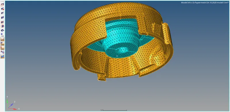
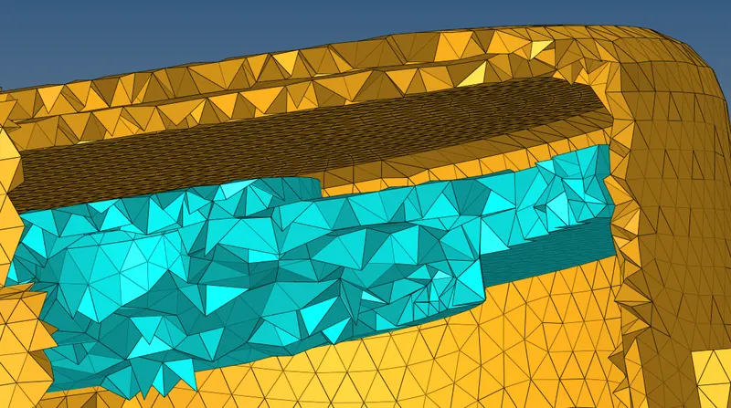
AIM: To create the tetramesh for the housing using 2D trias with the given element sizes and tetra collapse.
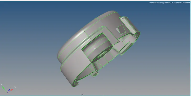
OPERATIONS:
2D>automesh to create tria elements with the given element size.
3D>tetramesh to create 3D tetra elements,tetra remesh.
PROCEDURE:
1.Give the values of target element and tet collapse in Preference>Criteria file>3D.
2.Mesh the part 1 of the component using 2D>automesh with the tria mesh type and element size with 5mm.
3.Create the tetra elements using 3D>tetra mesh after giving the tetra parameters and mesh the component.


4.Check for tet collapse in check elements.Remesh the component if tetra collapse value is above zero.
5.Same procedure follows to the part2 of housing as to meshing with 2D tria elements and then converting them into 3D tetra elements and check for tet collapse to be zero.
RESULT:Created 3D tetra meshing using 2D trias elements for the housing component.
ARM BRACKET
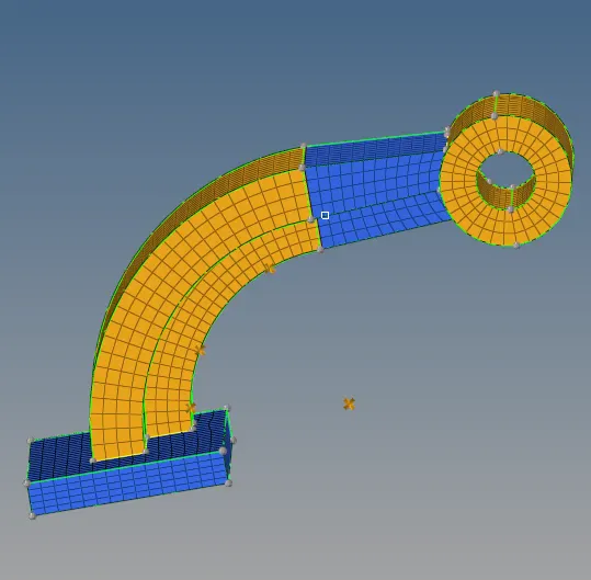
AIM:To create the Hexamesh for the Arm bracket using 2D quads with the given element size.
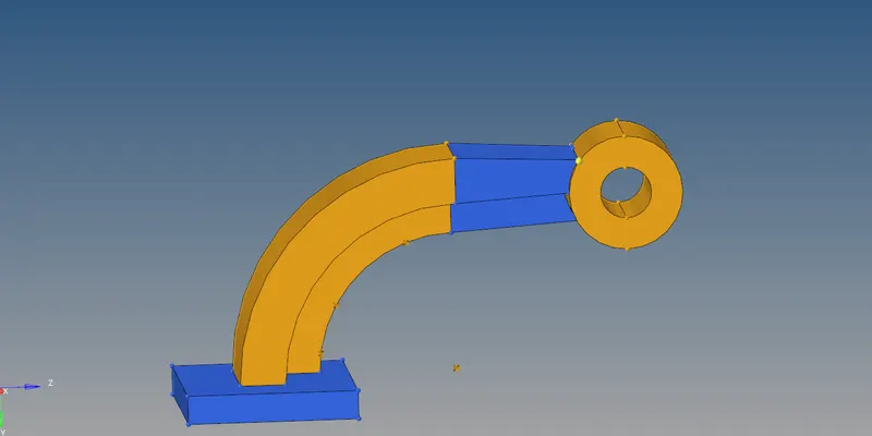
OPERATIONS:
2D>automesh to create tria elements with the given element size.
3D>Element offset,Linear solid,Spin and Solid map to create 3D Hexa elements.
PROCEDURE:
1.Mesh the base suirface with 2D quad elements.
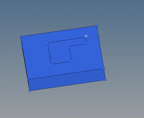
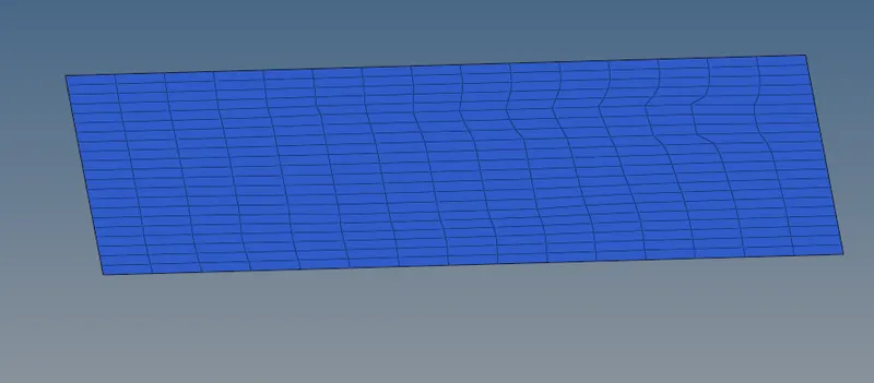
2.Creating the 3D hexa elements over the base using 3D>Element offset>solid layers.Select the 2D elements to offset ,3D faces,number of layers in the offset and total thickness.

3.To spin the mesh on a curve surface,need a center point to the circle to spin along the the origin.
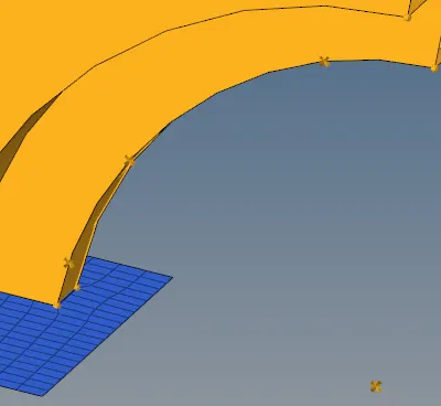
4.Now make the current component as arm curve.Select the 2d elements on base surface which resembles the arm curve pattern in spin elements,select axis and base point and make the angle of spin 90 degrees and spin.Hexa elements will be created on the armcurve.

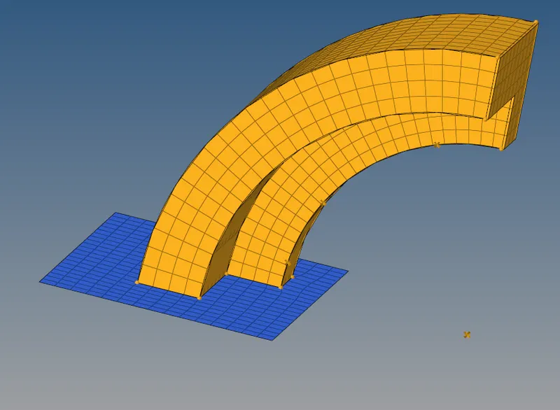
5.Now mesh the arm straight by creating faces on the curve by Tools>faces>component.In component,select arm curve and find faces which creates faces on arm curve.
6.Create the mesh on the face of arm straight which should match with elements on arm curve and create 2d mesh.
7.Now 3D>Linear solids, select the elements from arm curve and nodes to allign and to elements of arm straight and node allignment and give density as half of the arm curve and click solids.

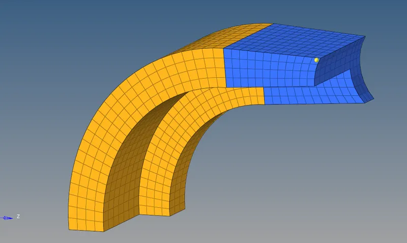
8.Organise the mesh with respect ot the components and delete faces.
9.Create the mesh on the boss surface with equal nodes in both small and large diameter where the nodes on boss and arm straight should match.
10.Project a duplicate node on the other side of the boss for allignment.
11.Now 3D>Solid map>general.Select the destination geometry(on the other side of mesh),along geometry>mixed select nodepath and elements to drag and give element size and mesh.

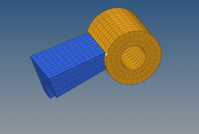
12.Delete the solid map and organise the elements with respect to the component.
RESULT:Created 3D Hexamesh on the arm bracket.
1D CONNECTIONS
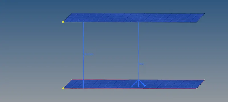
AIM:To make 1D connections on mesh plates.
PROCEDURE:
1.Mesh the other plate using 2D>Automesh.
2.Create a rod(TRUSS) element by 1D>Rods between the two plates by selecting the 2 nodes between them.

3.Create a rigid(RBE2) element by1D>rigids between the two plates by selecting multiple nodes on base mesh and single node on top mesh.

RESULT:Created 1D connections between two plates.
QUESTION NO:1-6
4.