Week 12 - Project-1
Manual mid surface extraction and mesh for Plastic side door component and Thickness assign for 2D Shell elements
INTRODUCTION:
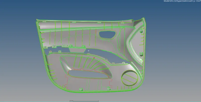
This project overview is to create the midsurface for the side door of a car by manually using offset,mesh the component,check for quality criteria and assign the thickness for the mesh to view the CAD model as FE model.
OBJECTIVE:
The objective is to create a midsurface manually to the component by offsetting the surface with respect to the thickness of the profile/feature/surface and organise the respective component/feature in the tab bar and extending the ribs/latches/features to the base surface to capture the midsurface properly.After creating the mid surface,meshing the component with proper mesh flow and checking for Element Quality after assigning the Quality Criteria file.After clearing the quality criteria,creating a property with respect to the thickness of the rib/feature/profile/component in the tab bar and assigning the thickness for the element as the feature/rib.
METHODOLOGY:
Geometry>Defeature>Surface fillets> used to remove the fillet regions which falls under minimum radius by selecting the fillets.
Geometry>Surface edit>Offset> to extract mid surface manually by selecting and creating a duplicate to the surface that wants to offset which captures the profile of the component and offsetting to half of the thickness which should offset to the mid.
Geometry>Surface edit>Extend> to extend the ribs/profiles/features to the base component to capture the parent geometry for creating mid surface.
Tools>Organise> used to organise extracted mid surface to a separate component or set of components in one component in Tab bar with respect to their thickness.
Geometry>Surface edit>Trim with lines> used to trim the surface like holes by selecting the surface and the lines that need to be trimmed normal to the surface.
Geometry>Surface edit>Trim with> surfaces> used to trim the surfaces.
Geometry>Quick edit>used to create lines,add/remove points,replace points,toggle lines,filler surface and project points to line.
Preferences>Criteria file settings> to set up the criteria for elements which applies during meshing.
2D>Automesh> to generate the mesh with given element size and to remesh
2D>Quality index> which can be used to optimise the failed elements by element optimisation,swap edge,drag tria elements,smoothing of elements,split/collapse edges,split quad elements,combine tria elements to create a smooth mesh flow.
2D>Smooth> used to smooth the elements to create proper flow and avoids curvy/wave flow in meshing.
PROCEDURE:
1.First defeature all the fillets which fall under minimal length and also that causes minimum element failure by selecting the fillets in geometry>defeature>surface fillets.
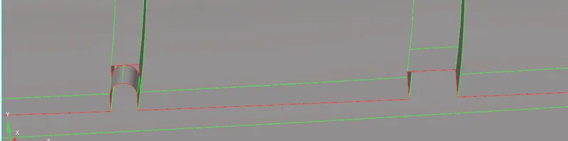
2.After defeaturing all the fillets, and extract the mid surfaces manually of the given side door component of a car individually i.e ribs,profiles,features,lower part of varying thickness by offsetting the surface by geometry>surface edit>offset.

3.Clean up the geometry to toggle the minimum length lines which creates failures in meshing.
4.Create a duplicate surface to the offset surface to the half of the thickness of the feature to extract mid surface.
5.Organise the extracted mid surface in a separate component in Tab bar mentioning its profile type following thickness which will be useful during assigning thickness mesh elements.

6.The 3D features or components in the model are to be meshed using tetra mesh.
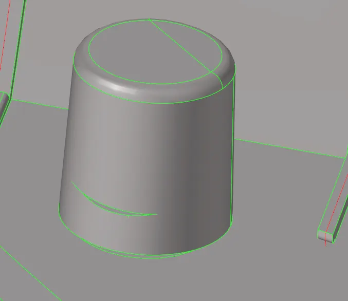
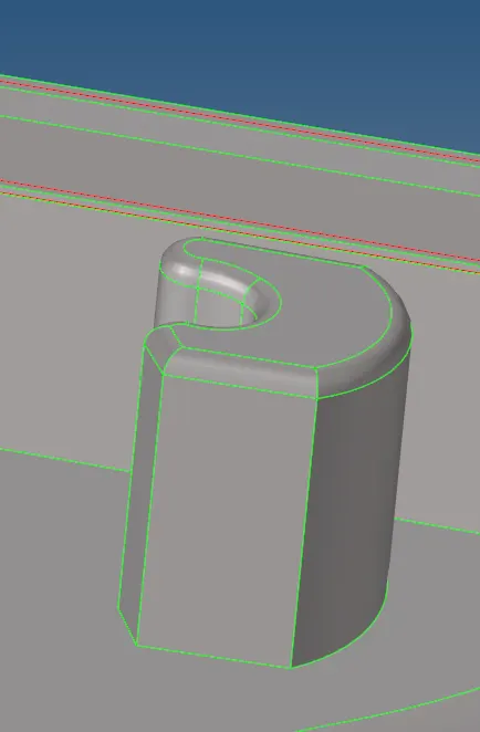
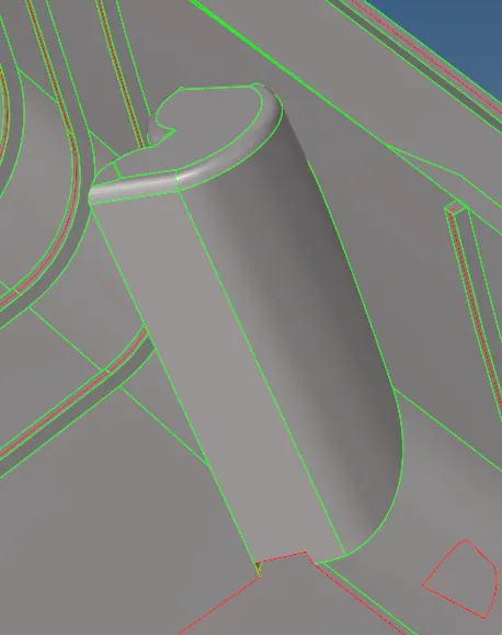
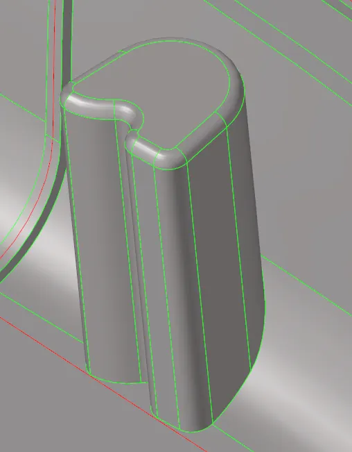
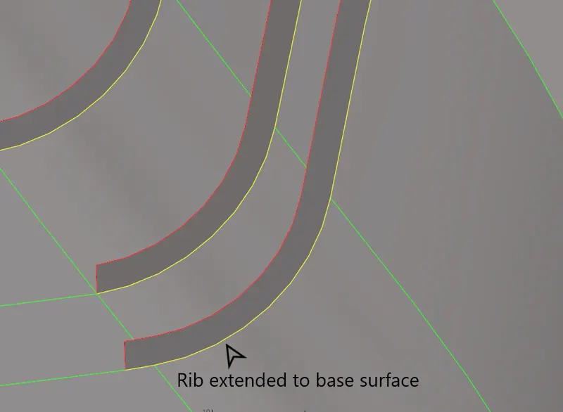
7.Extend the profiles i.e ribs/features of extracted mid surface to the extracted base component to capture the geometry by geometry>surface edit>extend.

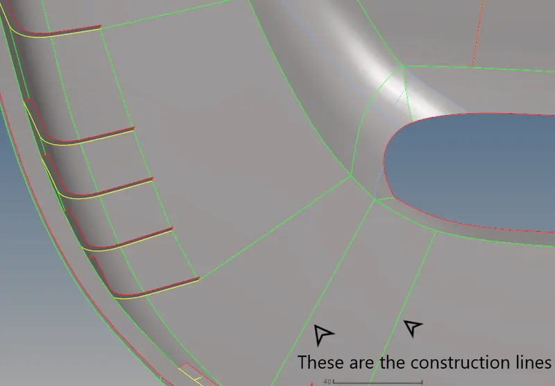
8.After extracting the mid surface of the component,remove the excess lines or the lines having a below 4mm in between them by toggling the lines and add the construction lines to create a smooth mesh flow by geometry>quick edit.

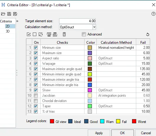
9.Assign the given criteria values in Criteria file settings by Preferences>Criteria file settings,save it and click Apply.
Target Element Length = 4mm
|
S.N |
Quality Criteria |
Value |
|
1 |
Aspect Ratio |
5 |
|
2 |
Skewness |
45 |
|
3 |
Warping |
15 |
|
4 |
Taper |
0.5 |
|
5 |
Min. Length |
2mm |
|
6 |
Max. Length |
6mm |
|
7 |
Min angle Quad |
45 |
|
8 |
Max angle Quad |
135 |
|
9 |
Min angle Tria |
20 |
|
10 |
Max angle Tria |
120 |
|
10 |
Tria % |
10 |
10.Mesh by divided surfaces by selecting the surface and arrange the nodes where tria elements are formed and to form quad elements and remesh the mesh where rotational quads and multiple trias formed by 2D>automesh.

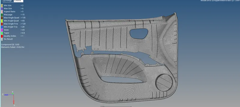
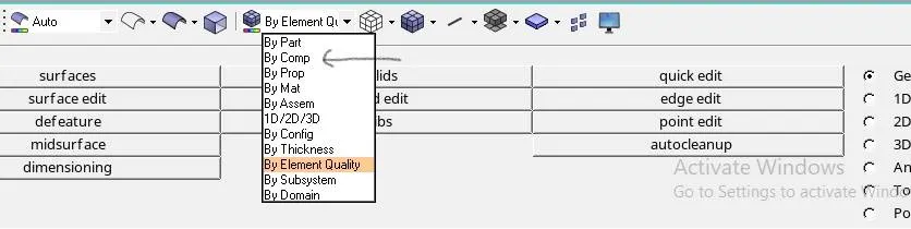
11.After meshing the surface,check for quality criteria where the elements were failing to reach its min values and max values by changing the mode from by comp to by element quality.
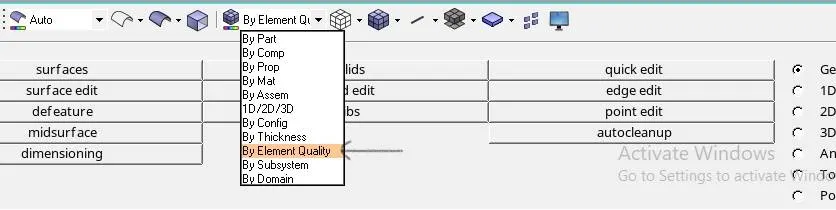
12.Clear the failures by using cleanup tools like quality index to smooth, optimise the failed elements by element optimisation,swap edge,drag tria elements,smoothing of elements,split/collapse edges,split quad elements,combine tria elements,replace nodes,distance,translate to clear warpage issues,aligning nodes by2D>quality index.

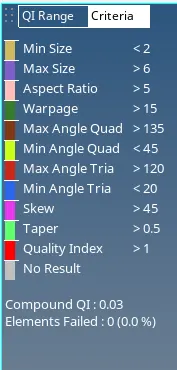
13.1D>Replace node to align the misalignment nodes or tools>edges by selecting the elements and giving the tolerance value which should not exceed minimum element length value and then Equivalence to get stitched and always keep the mesh in advanced mesh in Option “O” to keep the elements aligned.
14.Create the properties in the Tab bar and assign the thickness and card image in properties with respect to their components i.e ribs/features and then assign respective property in the component tree where FE model should capture CAD model.
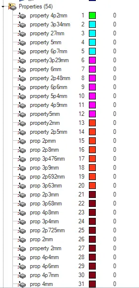
These are properties that are created with respect to their component.
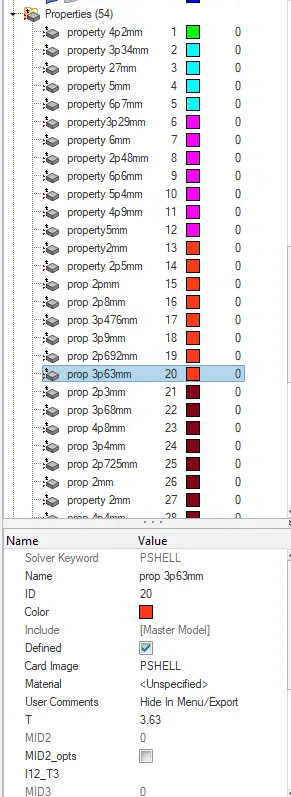
These are properties which are assigning thickness.
15.Make the trias to flow in a direction and avoid rotational quads.
16.Maintain mesh concentration.
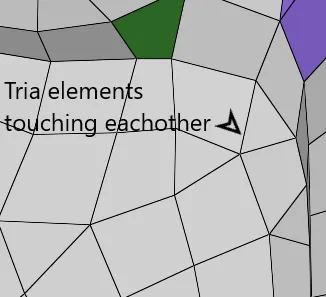
17.Opposite tria elements and tria elements touching each other should be avoided.
RESULT:
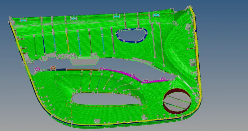
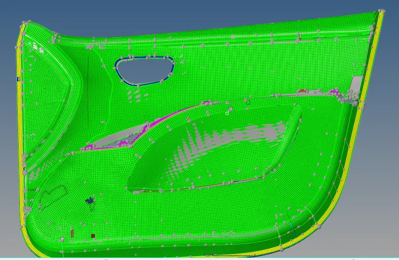
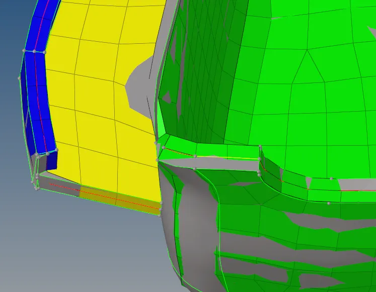
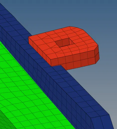
Created the 2D meshing for the car side door component with given criteria file and assigned thickness for 2Dshell elements.
CONCLUSION:
Manual mid surfacing is the only preferable method for Plastic Sheet components or Sheets with varying thickness to capture and maintain proper mesh concentration to get proper flow of mesh and make sure that the extracted mid surface should capture the Parent geometry.Mesh should capture the feature lines of mid surface.