Assignment 7
AIM:
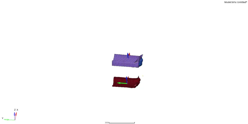
To perform the crash analysis on the side section of the car.
OBJECTIVE:
The main objective is to:
- Check the unit system if it is in (Mg mm s) or (Kg mm ms).
- Create an interface of Type 7 with the friction value of 0.2 and other recommended parameters for type 7.
- Check for any penetrations as no penetrations and intersections should present.
- Create a rigid wall with friction 0.1.
- Compare the model weight with the full scale 300k nodes model and use added masses to reach target weight 700kg while getting CG about the required range.
- Give an Initial velocity 35 mph to the car.
- Use the model checker to ensure good quality.
- Give the Time-step: 0.4 ms.
- Give Run time as 80 ms.
Output requests:
- Sectional force in the cross member.
- Intrusion at B pillar,hinge pillar and fuel tank region.Provide recommendation on what can help to reduce Fuel tank intrusion.
- Peak velocity of inner node of the door.
METHODOLOGY:
1.Importing the (0000.rad) File.
2.Model block>Cards>Being card>to check the dimensions.
3.Model block>Create>groups> to create the Interface of type 7 with recommended properties.
4.Tools>Penetration checker> to check for penetrations and intersections.
5.Model block>Create>Rigid>to create the Rigid Wall with required properties.
6.Solver block>Create>ADMAS>to create a mass to get the CoG about the required range at the centre.
7.Solver block>Create>Boundary conditions>INIVEL>to create the Initial Velocity.
8.Solver Block>Create>Boundary Conditions>SECT> SECT>to create the cross sections on the rails.
9.Solver Block>Create>Boundary Conditions>SKEW>MOV> to create the intrusions and peak velocity.
10.Performing the check for errors by Tools>Model Checker>Radioss Block and run the errors.
11.Giving the Time-Step and Run time Values.
PROCEDURE:
1.Import the Starter file(0000.rad) from Solver deck.
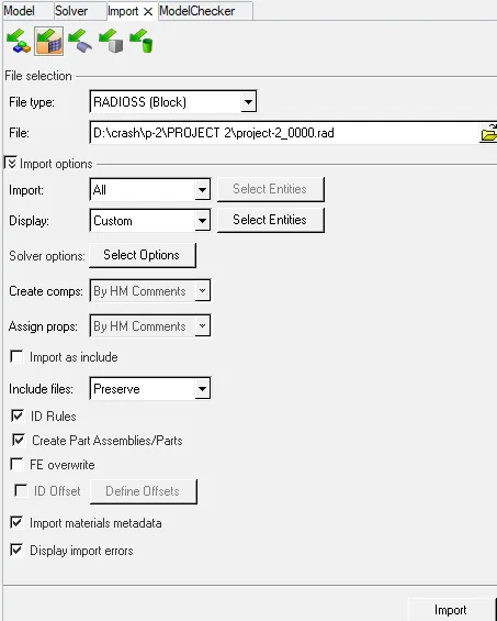
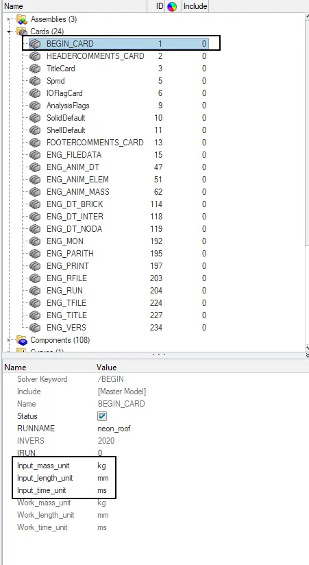
2.Checking the Units by Model Browser>Tab view>Cards>Begin card.In the Entity Editor Tab,check for the Input mass, Length, time units.
- The unit followed for the project is “Mass (Kg), Length (mm), and Time (ms)
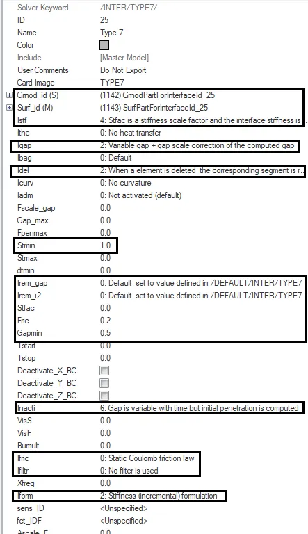
3.Create the Interface of TYPE 7 by Model Browser>Tab view>groups>create and name it as Type 7.Now assign the recommended properties in Type 7 interface which are:
- Istf (stiffness definition)=4
- Igap (gap/element option)=2
- Idel (Nodes and segment deletion)=2
- Irem_gap=2
- Irem_i2=0
- stfac=2
- Fric=0.2
- Gapmin=0.5
- Inacti=6
- Iform=2.
-Select the slave entities as components by Grnod-id(S)>select all components.
-Select the master entities as components by Surf-id(M)>select all components.
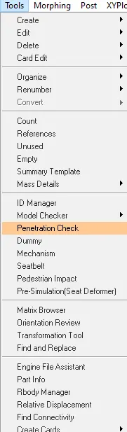
4.Check for any penetrations as no penetrations and intersections should be present by Tools>Penetration checker and select the group as type 7 and click check.It should notify as ‘0 penetrations’ which means there are no penetrations are present.
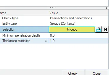
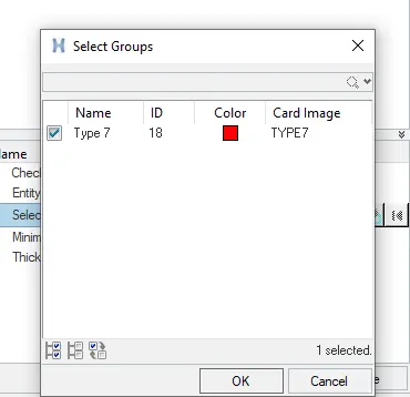
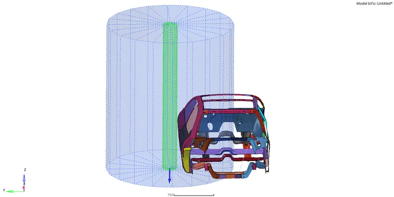
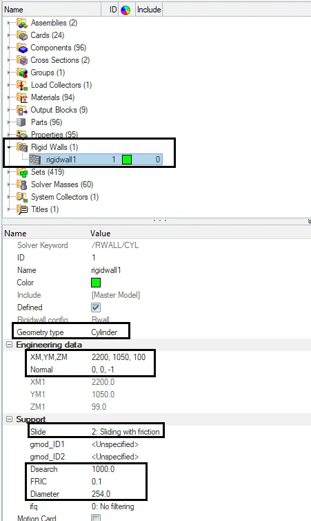
5.Create the Rigid Wall by Model Browser>Tab view>create>RWALL.In RWALL,select the geometry type as “Cylinder”.Click on the “XM, YM, ZM” and click on the arrow to select the node at the side middle section of the car as rigid wall needs to be created.
-Select the Normal and based on the direction of the rigid wall enter the value of z-axis as ‘-1’ as the rigid wall should be in z direction with respect to the impact of the car in y-direction.
-Assign the recommended properties which are:
- Slide= 2
- Dsearch=1000
- Fric=0.1
- Diameter=254.
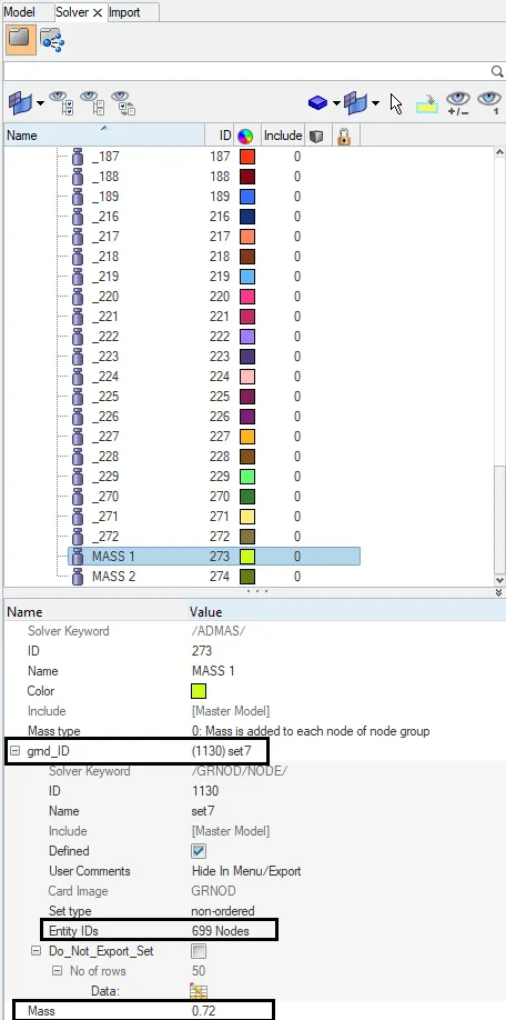
6.Create a COG(Centre of gravity) point by adding and balancing mass to get the CoG at the centre by Solver block>Create>ADMAS.Select the Mass type as 0 and in grnd_ID - Right click>create,in Entity_ID’s - select the nodes to add mass.Add a mass in MASS where the target weight at the centre should be 700kg.
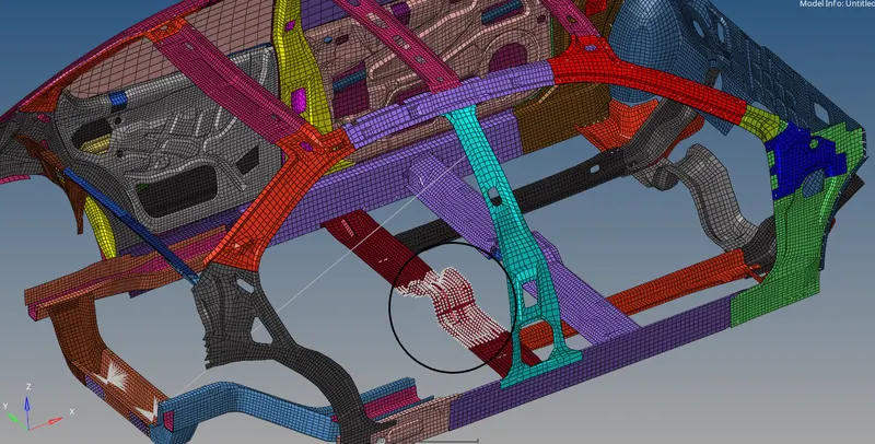
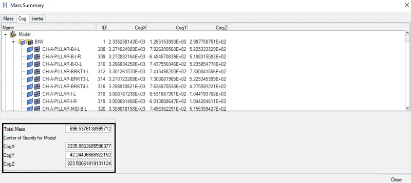
-After adding the mass check the total mass in Tools menu>Mass Details>Mass, COG and inertia.Select the CoG and check for the total mass and coordinates of x,y and z representing the CoG place.
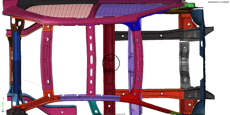
-Geometry>nodes - paste the coordinate values of x,y and z and plot the coordinate to view the CoG point.

7.Create the Initial Velocity by Solver Deck>right click on Tab view>Boundary Conditions>INIVEL.In INIVEL - in grnd_ID>Right click>create,in Entity_IDs - select components by clicking the arrow.Select all the components.
-In the Velocity components give the value of Vy as 15.64 as the car moving in Y-direction.
-The given initial velocity 35mph (miles per hour) is converted into the selected unit system.
1 mile = 1.609*10^6 mm and 1 hr = 3.6*10^6ms
1mph=0.44704mm/ms=>35mph=115.64mm/ms
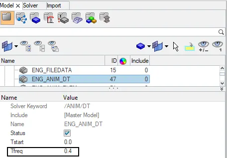
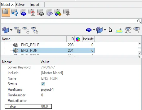
8.Give the Time-Step as 5 by Model Browser>Cards>ENG_ANIM_DT>Tfreq and Run time Value as 80 by Model Browser>Cards>ENG_RUN>Tstop.
9.Create the Cross Sections for the Cross Sections.
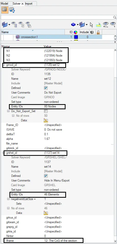
-To create the cross- section Solver browser>right click on Tab view>Create>SECT.In SECT - select the N1, N2, and N3 nodes and assign the values for delta T as 0.1 and alpha as 1.67.In grshel_id>right click>create,Select Entity_id - select 2 rows of elements at the region where N1,N2 and N3 are created.
-Create a Frame_id by Solver browser>right click on Tab view>Create>FRAME>MOV.Select the 3 nodes to create a local coordinate and assign the Frame_id in SECT card (or) create a 3rows of nodes on the rail by grnod_id>right click>create,Select Entity_id - select 3 rows of elements at the region where N1,N2 and N3 are created Give the Iframe=12.
-Creation of Cross sections for two the components follows the same procedure
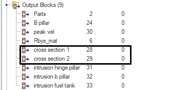
-The cross sections which are created need to be called in the Output Blocks by Model browser>Right-Click on the Output Blocks>Create.Name the created card as Cross Sections,In Entity-IDs - select all the cross sections.
10.Create the Intrusions on the Hinge pillar,B-pillar and Fuel tank region on right side of the car.
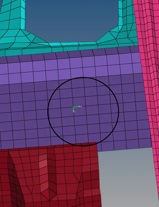
-Create the Intrusions by creating the skew on the opposite side of the impact(Right side) by Solver Browser>right click on the tab view>Create>SKEW>MOV.Select the 3 nodes ( origin, axis, Plane nodes) so the coordinates will be created.
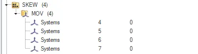
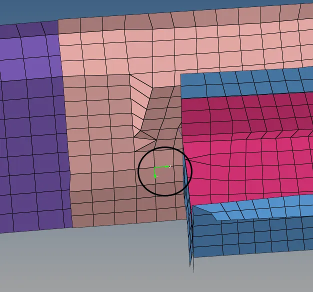
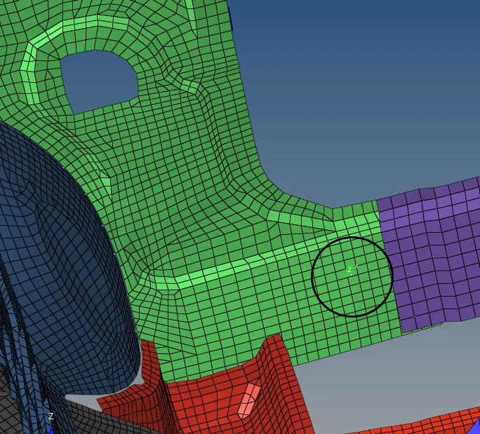
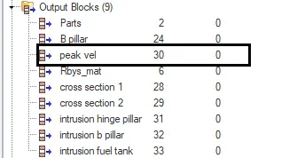
-The skews which are created need to be called in the Output Blocks by Model browser>Right-Click on the Output Blocks>Create.Name the created card as Intrusions,In Entity-IDs - select the intrusion node opposite to skew system and in Iskew - select the skew system created for that intrusion node.
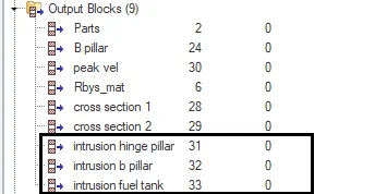
11.Create the Peak Velocity at the inside nearer to the impact area by Solver Browser>Right click on the Tab view>Create>SKEW.
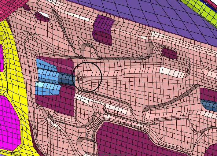
-The Peak Velocity card which is created in Solver deck needs to be called in the Output Blocks by Model browser>Right-Click on the Output Blocks>Create.Name the created card as Peak Velocity.In Entity_IDs select the node where Skew system created and in Iskew - select the skew system created for Peak Velocity..
12.After calling all the cross sections,intrusions and peak velocity in Output blocks, check for errors.To check errors go to Tool bar>Tools>Model checker>Radioss block.Right click on the errors and run.If any error pops up,clear those errors using Hypercrash.
13.To create the Animation file change the Client selector(ToolBar) from ‘Hypermesh’ to ‘HyperView’ to create the animation of impact.Upload the file (h3d) in ‘Load model and results’ and ‘Apply’.Save the animation video.
14.Now change the Client selector from ‘Hyperview’ to ‘HyperGraph 2D’ where you need to plot the graphs.
Error occur and Resolving:
Errors occurred:
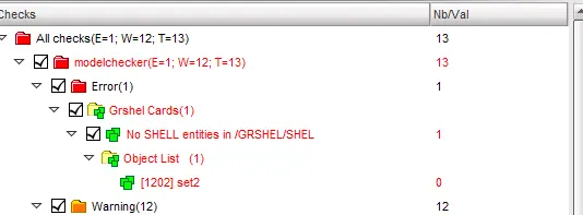
1.Grshel Cards - an empty shell sets will be created whenever opening the grshel_id when creating the Cross sections.
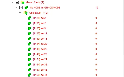
2.Grnod Cards - an empty node sets will be created whenever opening the grnod_id when creating the ADMAS.
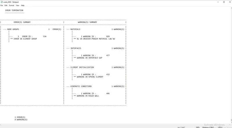
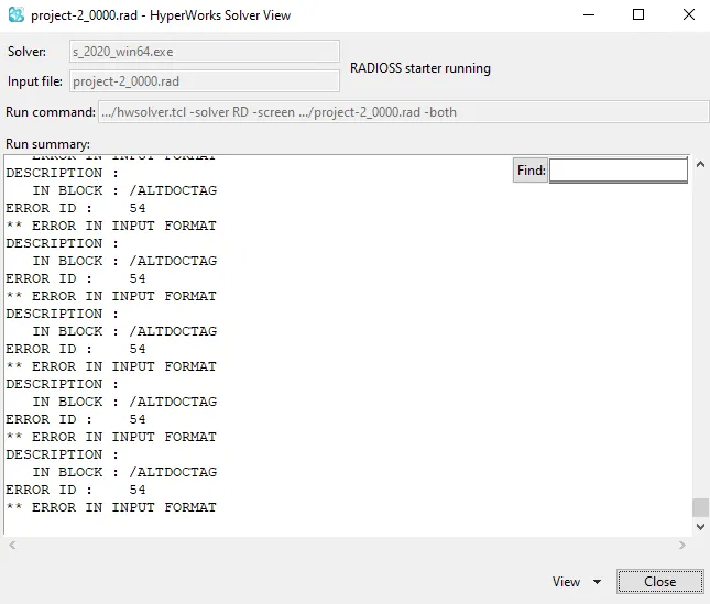
3.Error-ID 54 - an error will be created when an unsupported card is created in Cards.It will be created while importing the Hypercrash model to Hypermesh.
Resolving the errors:
1.Grshel cards - delete the empty sets in hypercrash.
2.Grnod cards - delete the empty sets in hypercrash.
3.Error-ID 54 - delete the unsupported card which is created in Cards.
-The errors which are created in Hypermesh need to be exported in a separate folder and import that folder in Hypercrash.Clear all the errors in Hypercrash and export that model in a folder.Now import the exported model(Hypercrash) and run the model.
INTRUSION:
Intrusion is the maximum vehicle deviation dimension of the impacting vehicle.
OBSERVATION:
From the animation - The right portion of the car is deforming more than the left portion during the impact.
From the Graphs:
1.Hinge pillar:
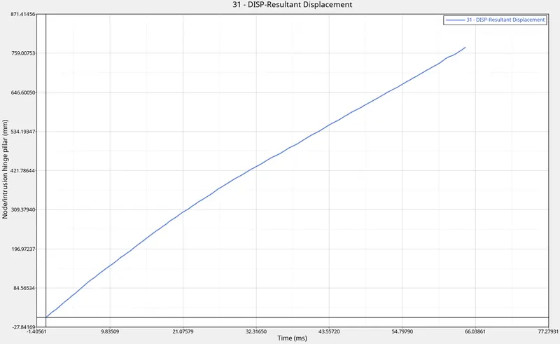
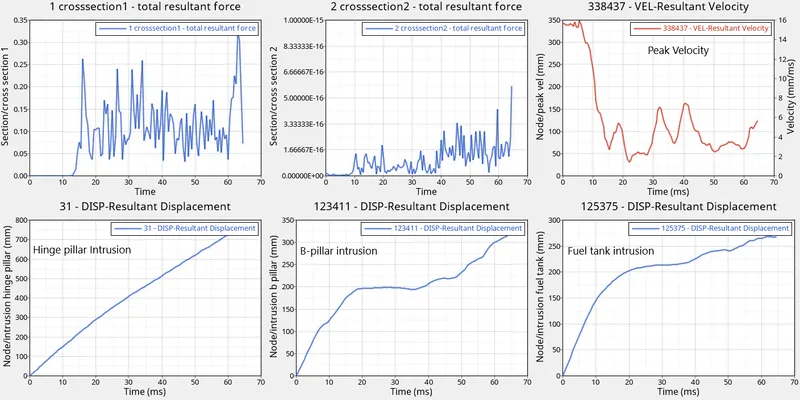
- From the graph,due to impact force,the dispalcement from the left side of car at time 64ms(apprx)-760mm(apprx),which is increasing linearly.
2.B-pillar:
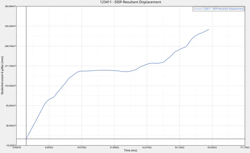
- From the graph,due to the impact force,the dispalcement from the left side of car at time 64ms(apprx) - 320mm(apprx),whch is increasing gradually.
3.Fuel tank region:
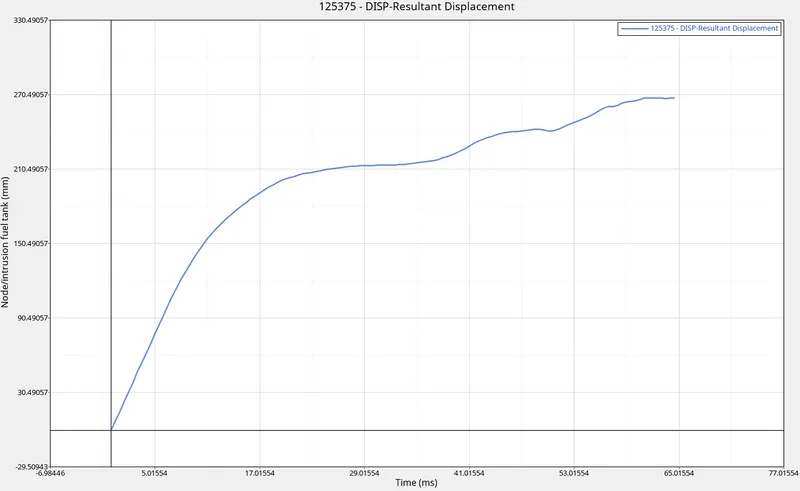
- From the graph,due to the impact force,the dispalcement from the left side of car at time 65ms(apprx) - 270mm(apprx),which is increasing gradually.
4.Cross Sections:
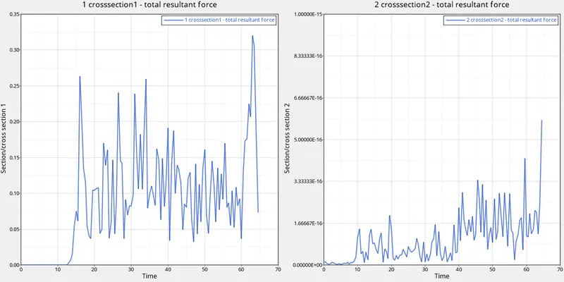
- From the Graph,the force on one rail maintains constant upto 10ms and increased upto 0.33kN(peak) and other rail the force increased gradually from 10ms and attains peak force.
5.Peak Velocity:
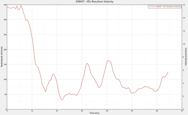
- From the graph,the displacement gradually decreases from 350mm and increases with minimum deviation at 30ms and then decreases.
ENERGIES:
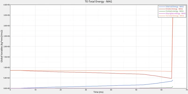
- The Hourglass Energy remains constant
- The Contact Energy reamins constant.
- The internal Energy is increasing and Kinetic Energy reamins constant and increases suddenly.
- The Total Energy remains constant.
1.Fuel Tank Intrusions can be reduced by the modifyng design by adding rails and materials.
RESULT:
Completed the simulation for the frontal crash and Plotted the graphs.