Project
AIM:
To study and analyse the BAJA All Terain Vehicle using Simulink and compare different models analysis.
OBJECTIVE:
1.To prepare a detailed Technical report explaining about the ATV model and the model blocks.
2.Compare the different models and observe the results.
THEORY:
ALL TERRAIN VEHICLE(ATV):
An All Terrain Vehicle (ATV), is a vehicle that also known as a light utility vehicle (LUV), a quad bike which travels on low-pressure tires, with a seat that is straddled by the operator, along with handlebars for steering control. As the name implies, it is designed to handle a wider variety of terrain than most other vehicles.While the deep treads on some ATV tires are effective for navigating rocky, muddy and root covered terrain, these treads are also capable of digging channels that may drain bogs.
SAE BAJA:
Baja SAE is an Collegiate Design Series competition run by the Society of Automotive Engineers International (SAE International). Teams of students from Universities all over the world design and build small off road cars. The cars all have engines of the same specifications. The goal in Baja SAE racing is to design, build and race off-road vehicles that can withstand the harshest elements of rough terrain. The object of the competition is to simulate real-world engineering design projects and their related challenges. Each team is competing to have its design accepted for manufacture by a fictitious firm.
PROCEDURE:
Blocks used in Model:
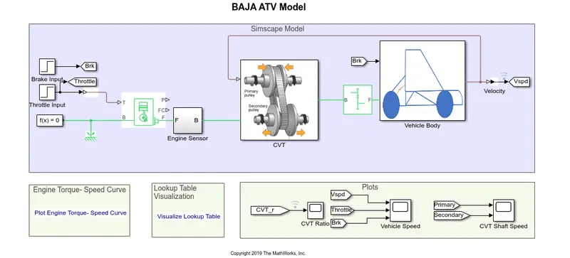
GENERIC ENGINE:
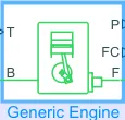
Represents a system-level model of spark-ignition and diesel engines suitable for use at initial stages of modeling when only the basic parameters are available. Optional idle speed and red line controllers are included. If the engine speed falls below the Stall speed, the engine torque is blended to zero. If the engine speed exceeds the Maximum speed, the simulation stops and issues an error message.
The throttle input signal T lies between zero and one and specifies the torque demanded from the engine as a fraction of the maximum possible torque.
Connections F and B are mechanical rotational conserving ports associated with the engine crankshaft and engine block, respectively.
Connections P and FC are physical signal output ports through which engine power and fuel consumption rate are reported.
ENGINE SENSOR SUBSYSTEM:
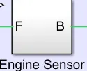
Rpm Sensor (Ideal Rotational Motion Sensor):
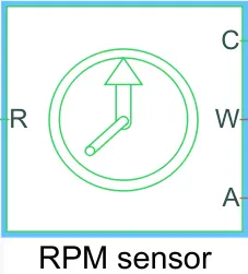
The block represents an ideal mechanical rotational motion sensor, that is, a device that converts an across variable measured between two mechanical rotational nodes into a control signal proportional to angular velocity or angle.
Connections R and C are mechanical rotational conserving ports.
Connections W and A are physical signal output ports for velocity and angular displacement, respectively.
PS Terminator:

Use this block to terminate physical signal outputs. Unconnected physical signal output ports do not generate warnings, but connection to a PS Terminator can be used to indicate that the signal was not inadvertently left unconnected.
CVT SUBSYSTEM (Continuously Variable Transmission):
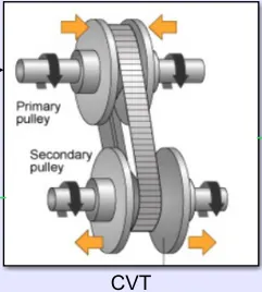
A Continuously Variable Transmission (CVT) is an automatic transmission that can change seamlessly through a continuous range of gear ratios. This contrasts with other transmissions that provide a limited number of gear ratios in fixed steps.
The most common type of CVT uses two pulleys connected by a beltor chain, however, several other designs have also been used at times.
Variable Ratio Transmission:
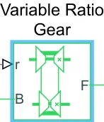
Represents a variable ratio gearbox such as implemented by mechanical belt CVT, electric, or hydraulic transmissions.
The physical signal input r defines the ratio of input to output angular shaft velocities.
Connections B (base) and F (follower) are mechanical rotational conserving ports. Specify the relation between base and follower rotation directions with the Output shaft rotates parameter.
SIMPLE GEAR:
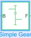
Represents a fixed-ratio gear or gear box. No inertia or compliance is modeled in this block. You can optionally include gear meshing and viscous bearing losses.
Connections B (base) and F (follower) are mechanical rotational conserving ports. Specify the relation between base and follower rotation directions with the Output shaft rotates parameter.
VEHICLE BODY SUBSYSTEM: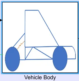
Tire:

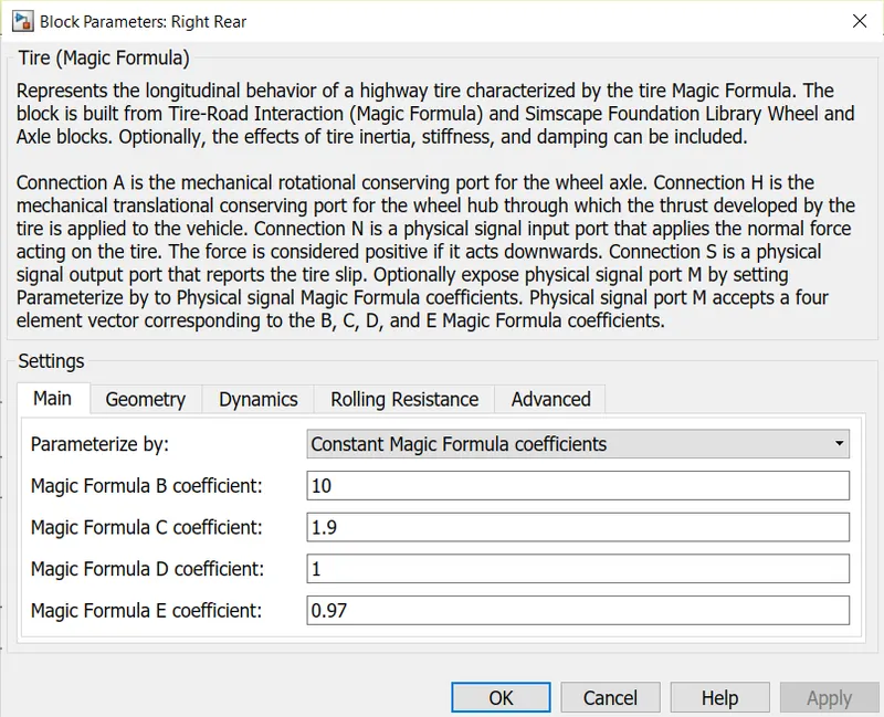
Represents the longitudinal behavior of a highway tire characterized by the tire Magic Formula. The block is built from Tire-Road Interaction (Magic Formula) and Simscape Foundation Library Wheel and Axle blocks.
Connection A is the mechanical rotational conserving port for the wheel axle.
Connection H is the mechanical translational conserving port for the wheel hub through which the thrust developed by the tire is applied to the vehicle.
Connection N is a physical signal input port that applies the normal force acting on the tire. The force is considered positive if it acts downwards.
Connection S is a physical signal output port that reports the tire slip.
Double Shoe Brake:
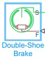
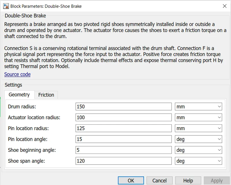
Represents a brake arranged as two pivoted rigid shoes symmetrically installed inside or outside a drum and operated by one actuator. The actuator force causes the shoes to exert a friction torque on a shaft connected to the drum.
Connection S is a conserving rotational terminal associated with the drum shaft.
Connection F is a physical signal port representing the force input to the actuator. Positive force creates friction torque that resists shaft rotation.
Vehicle body:
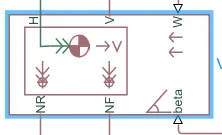
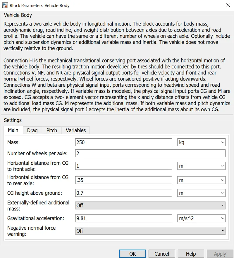
Represents a two-axle vehicle body in longitudinal motion. The block accounts for body mass, aerodynamic drag, road incline, and weight distribution between axles due to acceleration and road profile. The vehicle can have the same or a different number of wheels on each axle.
Connection H is the mechanical translational conserving port associated with the horizontal motion of the vehicle body. The resulting traction motion developed by tires should be connected to this port.
Connections V, NF, and NR are physical signal output ports for vehicle velocity and front and rear normal wheel forces, respectively. Wheel forces are considered positive if acting downwards.
Connections W and beta are physical signal input ports corresponding to headwind speed and road inclination angle, respectively.
KNOB
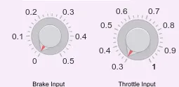
Set a value to tune parameters or variables
BAJA ATV WITHOUT DASHBOARD(cvtModel):
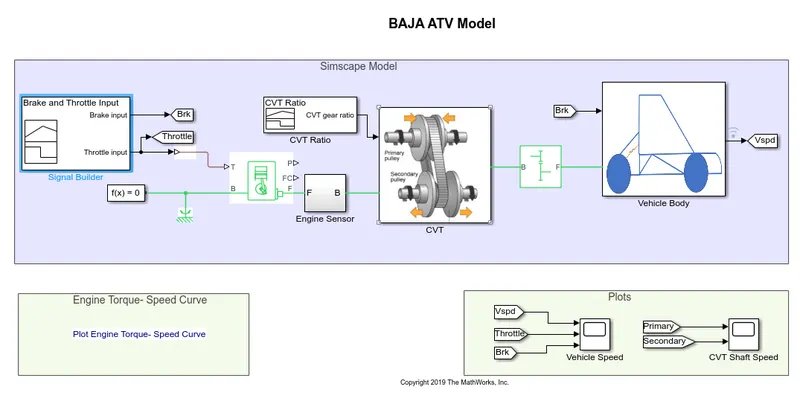
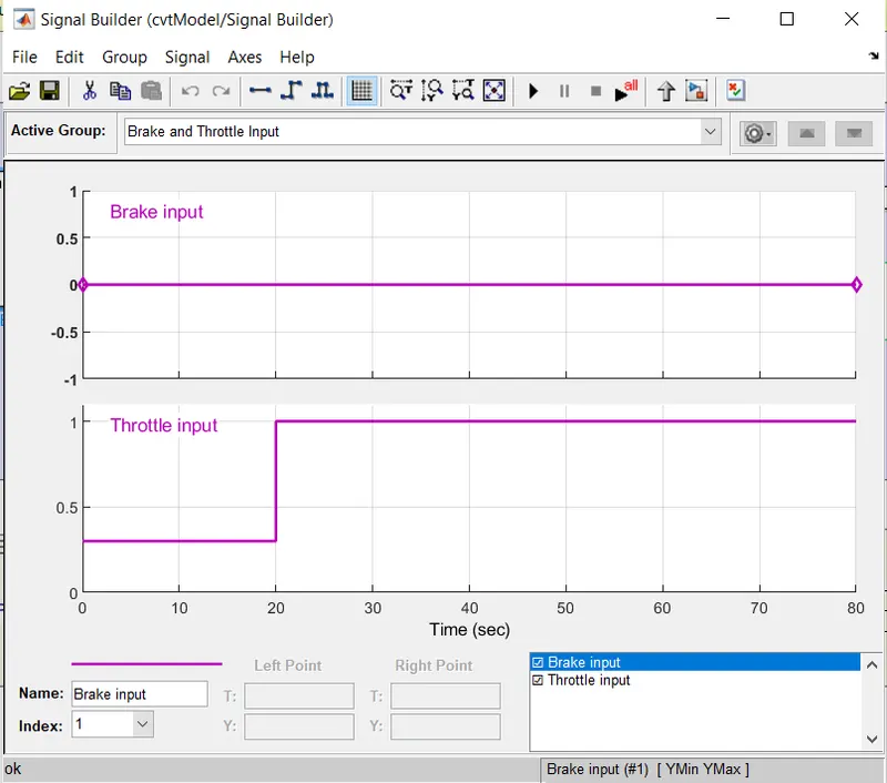
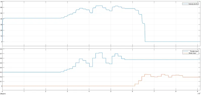
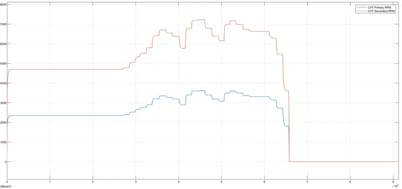
This model uses Signal builder for Brake and Throttle as inputs in the form of signal and with fixed gear ratio.
Brake and Throttle inputs
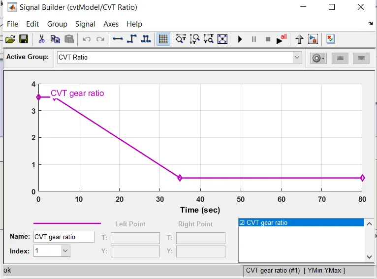
CVT gear ratio
OUTPUTS:
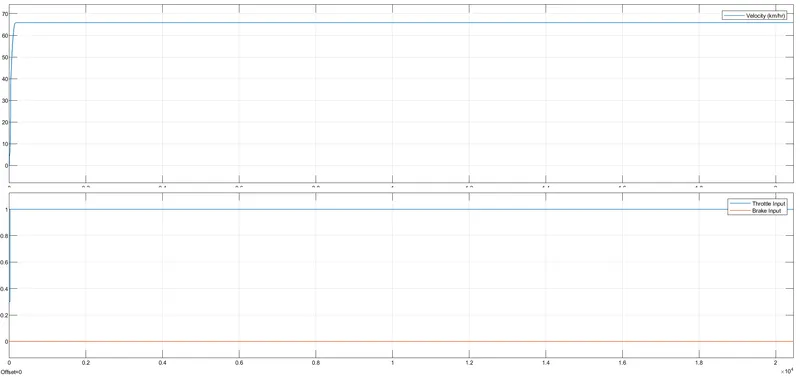
Vehicle speed
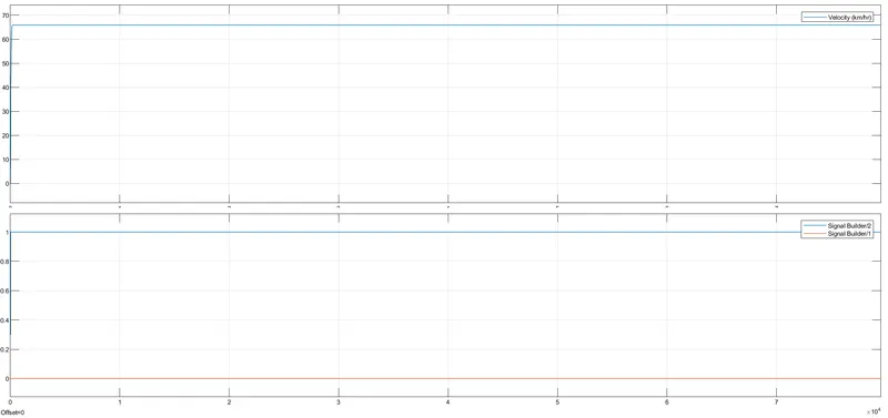
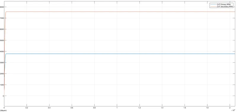
CVT shaft speed
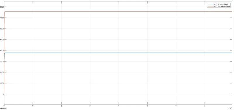
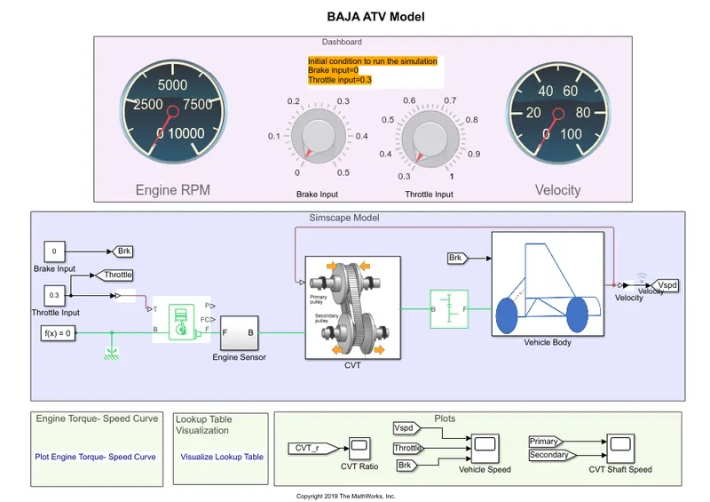
BAJA ATV WITH DASHBOARD(cvtModel_dashboard):
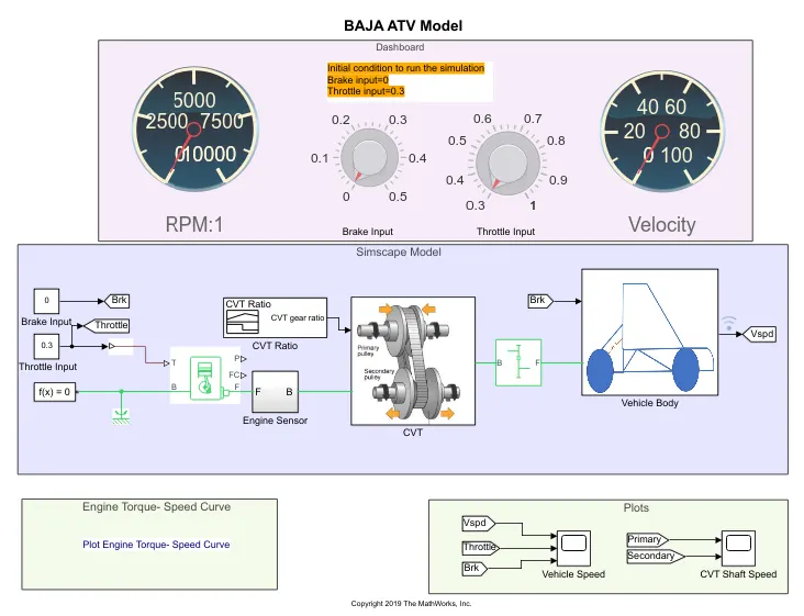
In this model Throttle and Brake input can be operated using the knobs and with fixed gear ratio.
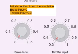
CVT gear ratio
OUTPUTS:
Vehicle speed
CVT shaft speed
LOOKUP TABLE:
A lookup table is an array of data that maps input values to output values. You can use a lookup table to model your system, and tune the table data using measured data from your system. The resulting table represents a static system.
The behavior of actual physical systems often varies with time due to wear, environmental conditions, and manufacturing tolerances.
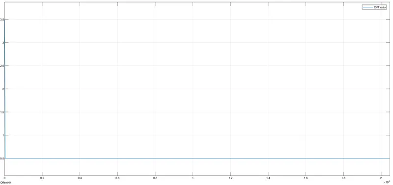
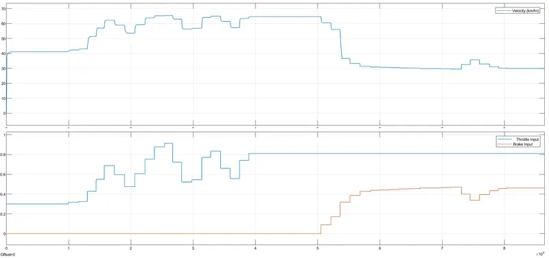
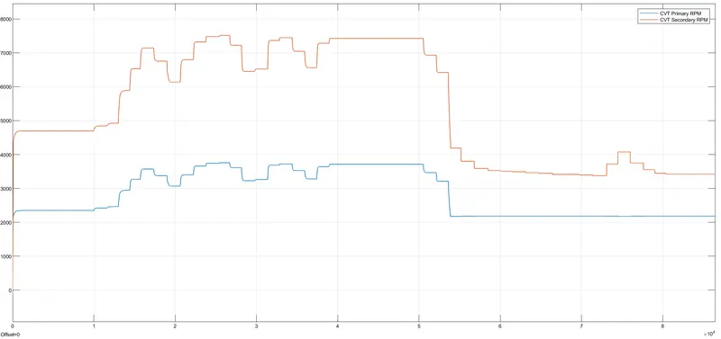
BAJA ATV WITHOUT DASHBOARD USING LOOKUP TABLE(cvtModel_mapped):
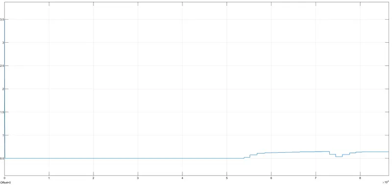
In this model there will be no fixed gear ratio and the Gear ratio changes with respect to the Velocity of the body(where we can assume a real scenario in CVT in mapped model).
OUTPUTS:
CVT ratio:
Vehicle speed:
CVT Shaft Speed:
BAJA ATV WITH DASHBOARD USING LOOKUP TABLE(cvtModel_dashboard_mapped):
In this model Throttle and Brake input can be operated using the knobs and the Gear ratio changes with respect to the Velocity of the body..
OUTPUTS:
CVT ratio:
Vehicle speed:
CVT Shaft Speed:
RESULT:
Simulated and Analysed the BAJA ATV models.