Week 11 - Final project
AIM:
To design and develop a Car Side Door Interior Panel from the given Class A surface.Assign the thickness and attach the Engineering Features like ribs,locators and dog houses with Push Clips.
METHODOLOGY:
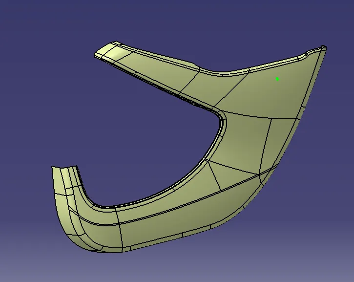
- Extract the surfaces of Arm rest,Lower substrate,Map pocket and Master Sections from the given component using Multiple Extract option by selecting the surfaces.
- Create the Tooling axis for the components by Point-Direction using Line definition.
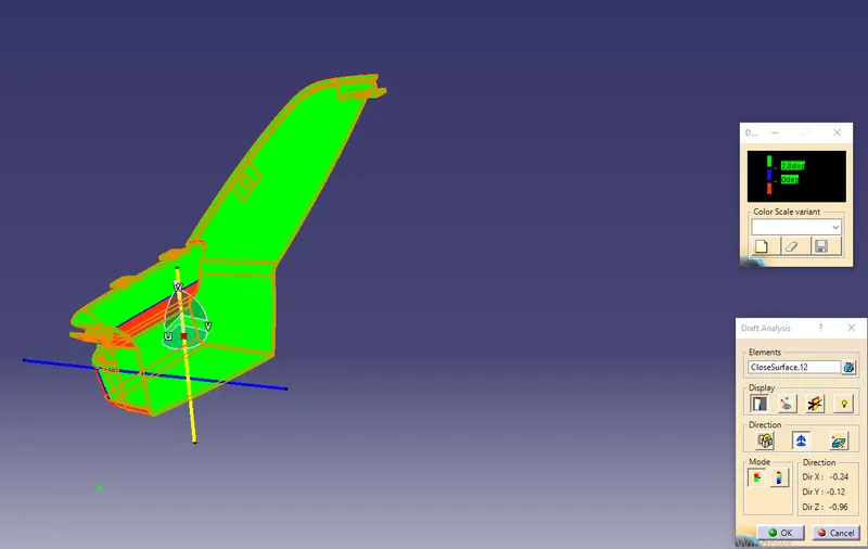
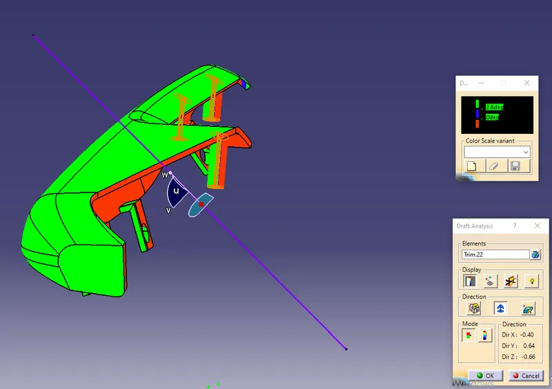
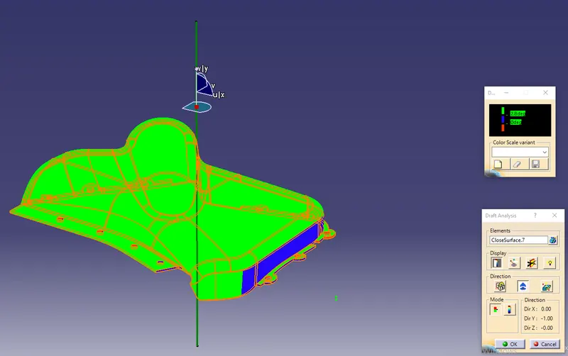
- Generate the draft analysis on the Class A components by Feature Draft Analysis by moving the compass to tooling axis.
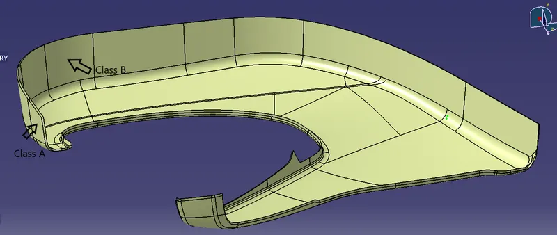
- Create the Class B surface by Offsetting the Class A to the thickness of 2.5mm.
- Create the Class C surface using the Sweep option with a draft angle of 3 degrees.
- Create the Flanges to the components as per given Master sections.
- Create the Heat stakes as per master sections for flanges.
- Create the Dog house and Push clips for the component as per dimensions.
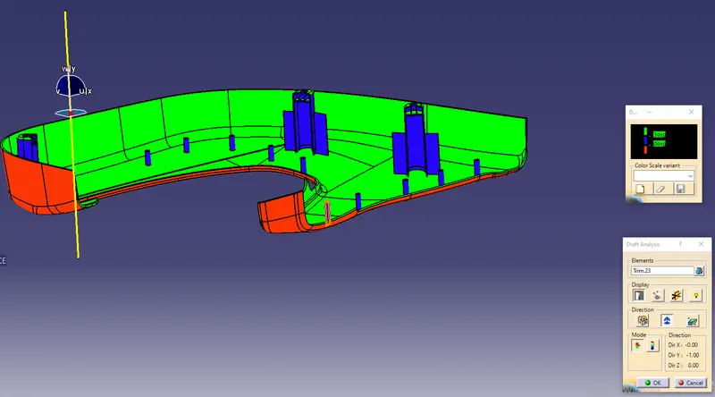
- Unitrim the features with the Main component using Boolean Operations and Generate the Draft Analysis on the Final Component.
MASTER SECTIONS:
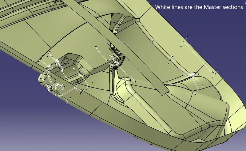
DOOR TRIM PANEL CLASS A SURFACE:
ARM REST:
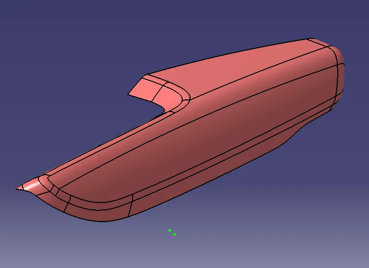
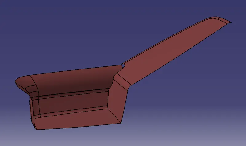
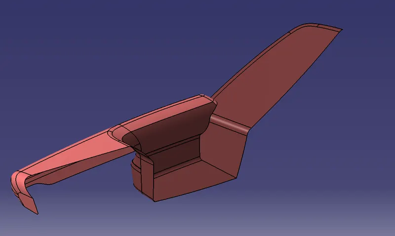
LOWER SUBSTRATE:
MAP POCKET:
DOG HOUSE:
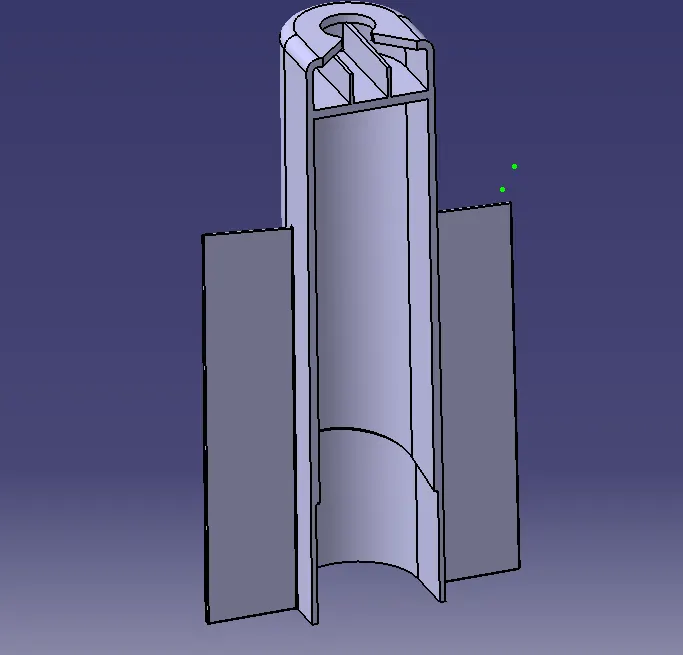
- Dog houses are used as supporting features which are used in plastic trim designs.
PUSH CLIPS:
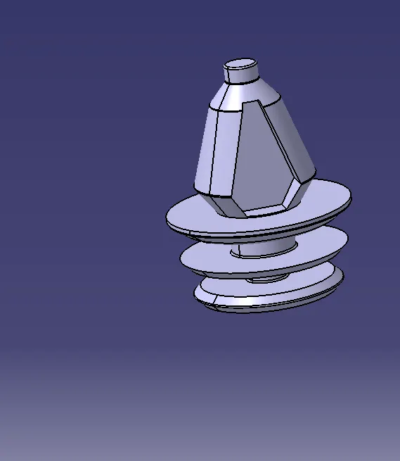
- Push clips are used to fix a component to another component.
FLANGES:
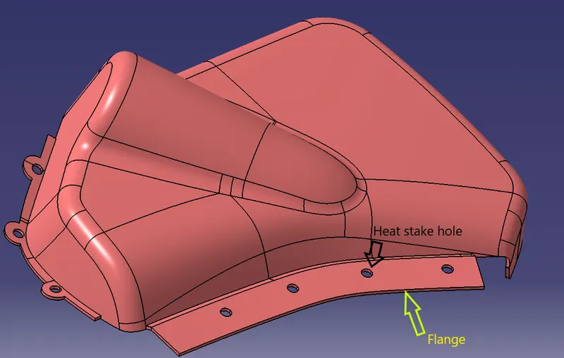
- Flanges are used to hold the other component with the heat stakes.
TOOLING AXIS:
- Create a Tooling axis in which it is the direction where Core and Cavity moves.The Tooling direction should be perpendicular to the surface.
- Create the Tooling axis using Line definition by Line type: Point-Direction and Point: selecting the point on surface and Direction: Perpendicular to surface.
HEATSTAKES:
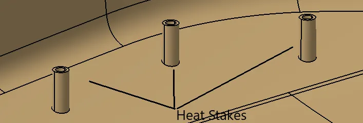
- Heat stakes are the parts used to join two dissimilar parts together and this process of joining is called Heat Staking.
DRAFT ANALYSIS ON CLASS A:
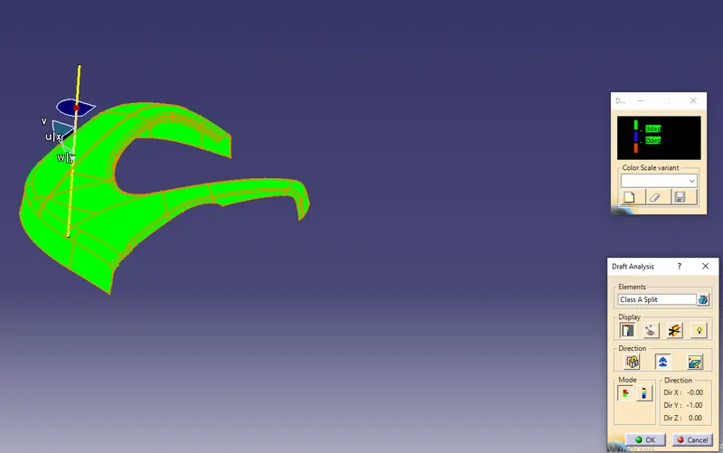
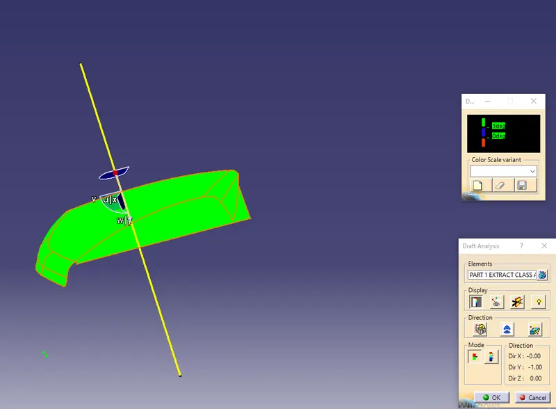
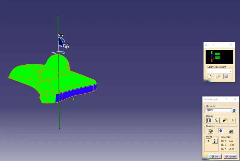
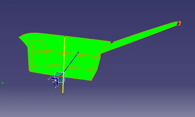
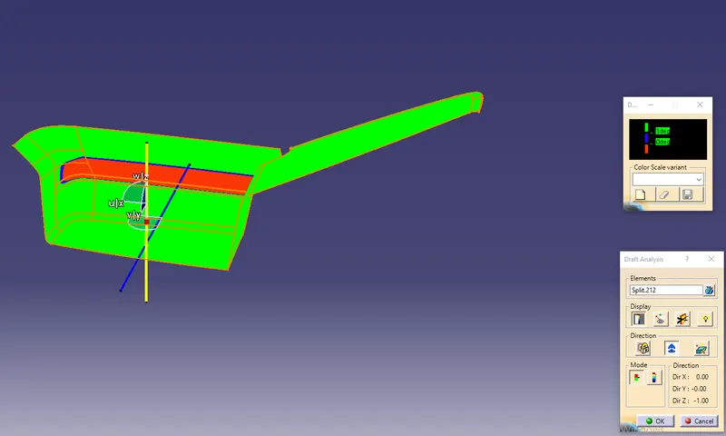
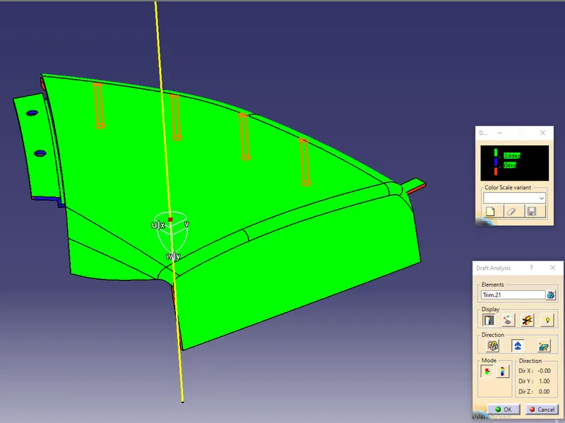
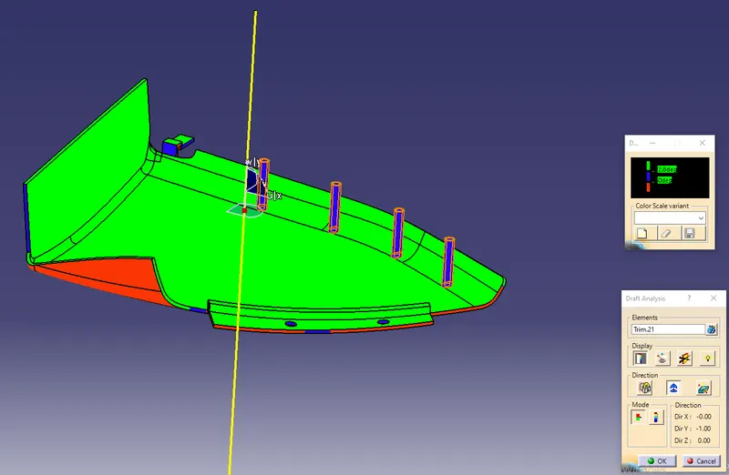
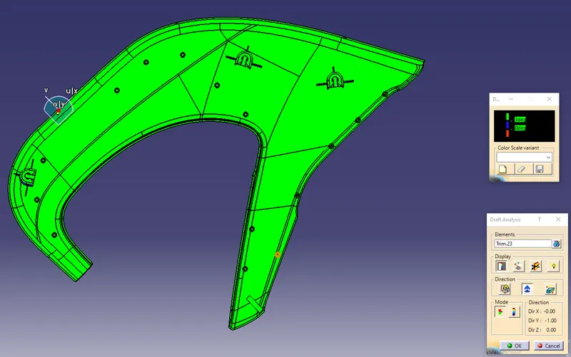
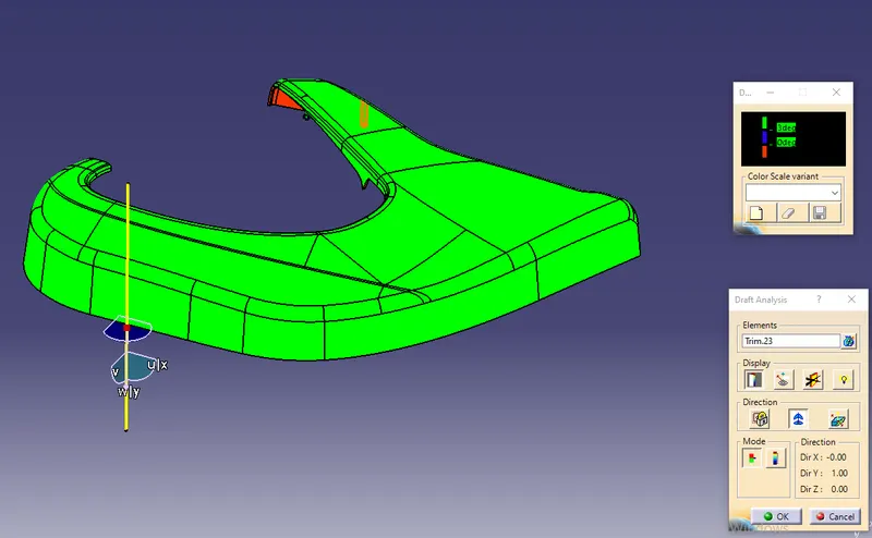
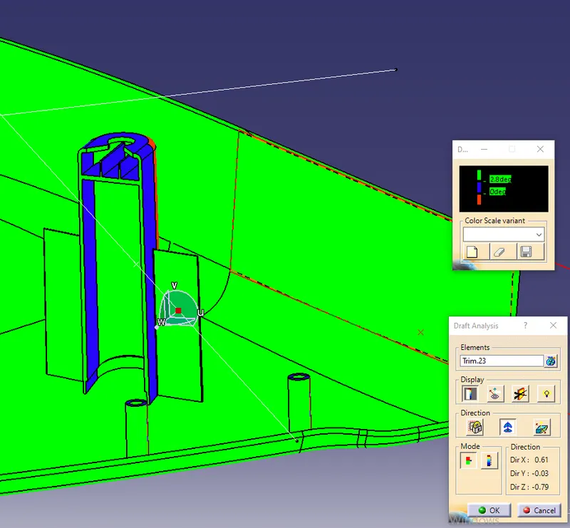
- Draft Analysis is a technique to analyze the component whether it can be manufacturable and able to eject from the mould without damaging the component.A 3° draft angle which is widely acceptable and minimum of 0.5° is provided to the component.
- Extract all the surfaces from the given Class A Interior side door Panel as Arm rest,Lower Substrate and Map Pocket.Generate the Draft Analysis of the Class A surfaces.
LOWER SUBSTRATE:
Creation of Class B surface:
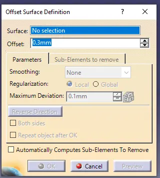
- Offset the Class A surface using the Offset command by Surface: Select the surface and Offset: distance of 2.5mm which is the thickness measured from the Master sections.

Creation of Class C surface:
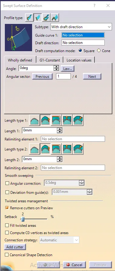
- Create the Class C surface using the Sweep option. In Sweep - Profile type - 2 ,Subtype - with draft direction,Guide curve - Boundary of surface, Angle: 90 degrees and the swept surface should be perpendicular to the class A and it should be cleared in the tooling direction.

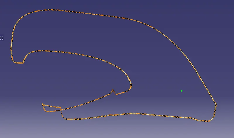
- Join the Class A,Class B and Class C surfaces without an open boundary or Trim the surfaces with an excess surface and then Create the Solid part using Close surface in Part design.
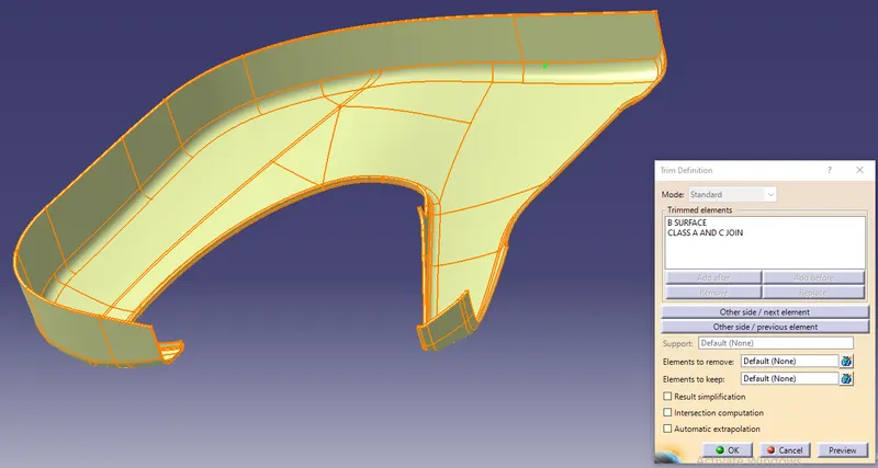
- Create the Heat stakes on Lower substrate as per Master sections.
MAP POCKET:
Creation of Class B surface:
- Offset the Class A surface using the Offset command by Surface: Select the surface and Offset: distance of 2.5mm which is the thickness measured from the Master sections.
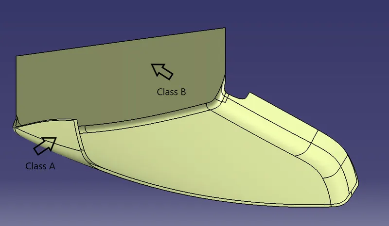
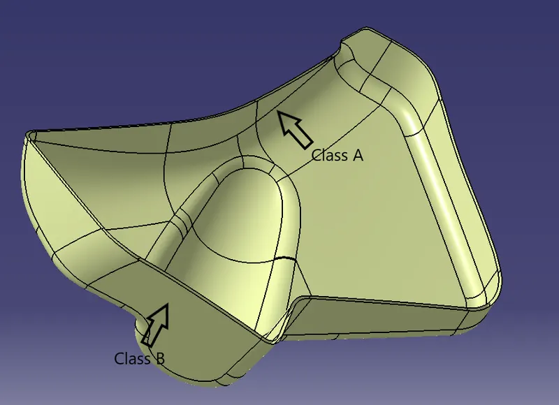
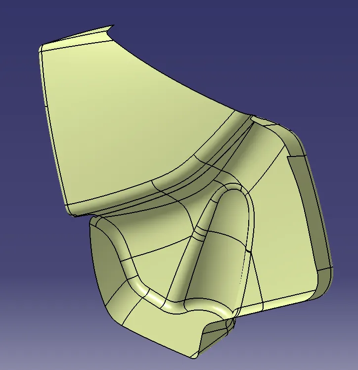
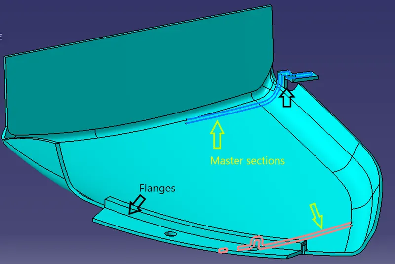
- Create the Map Pocket component as two parts and attach the parts with heat stakes.Create the flanges as per given Master section.
Creation of Class C surface:
- Create the Class C surface using the Sweep option. In Sweep - Profile type - 2 ,Subtype - with draft direction,Guide curve - Boundary of surface, Angle: 90 degrees and the swept surface should be perpendicular to the class A and it should be cleared in the tooling direction
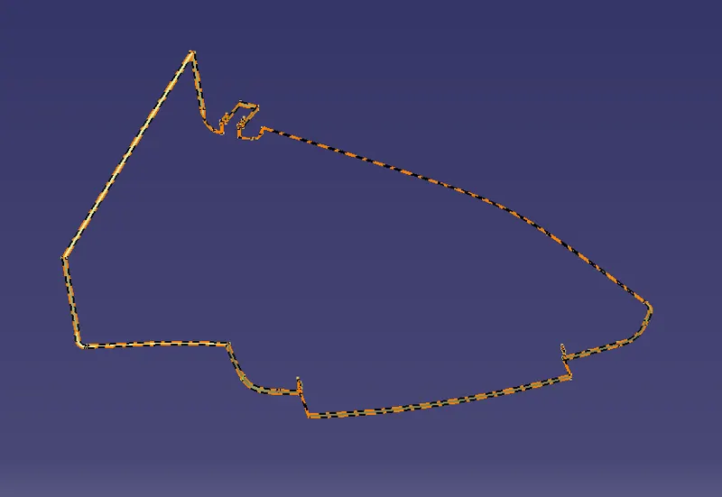
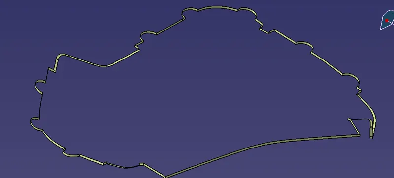
- Join the Class A,Class B and Class C surfaces without an open boundary or Trim the surfaces with an excess surface and then Create the Solid part using Close surface in Part design.
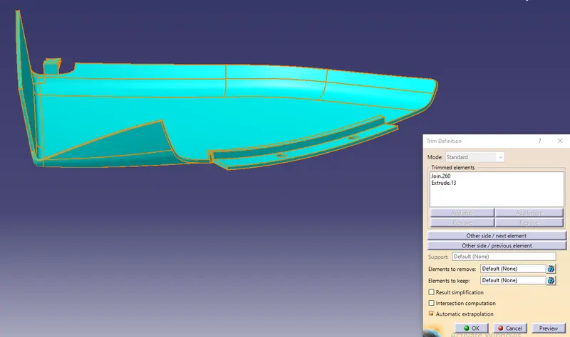
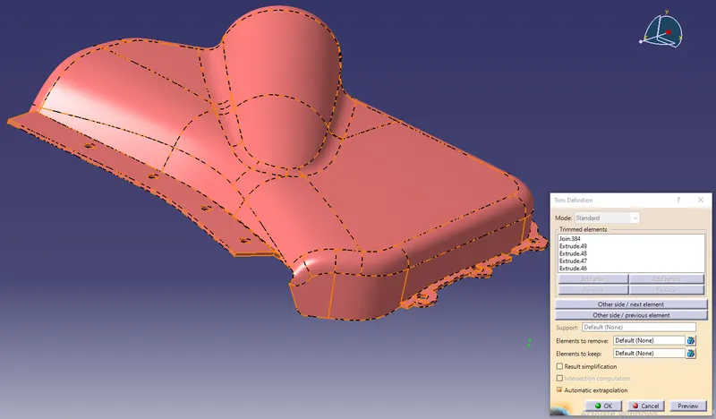
- Create the Flanges on the Map Pocket as per the Master section.Flanges are used to hold the other component with the heat stakes.
ARM REST:
Creation of Class B surface:
- Offset the Class A surface using the Offset command by Surface: Select the surface and Offset: distance of 2.5mm which is the thickness measured from the Master sections.
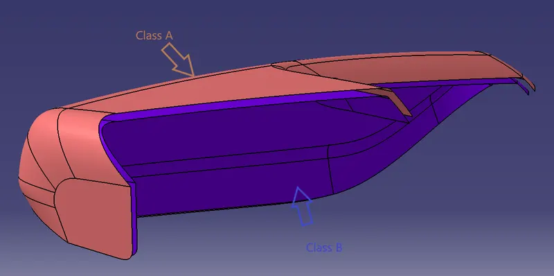
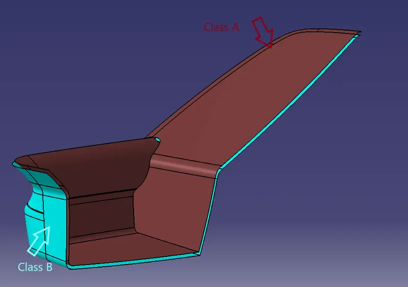
- As the complete Armrest cannot be formed by the Main Tooling direction due to the pocket,we need to provide the Slider axis.Create it in two different parts and create tooling axis for two parts.
Creation of Class C surface:
- Create the Class C surface using the Sweep option. In Sweep - Profile type - 2 ,Subtype - with draft direction,Guide curve - Boundary of surface, Angle: 90 degrees and the swept surface should be perpendicular to the class A and it should be cleared in the tooling direction.
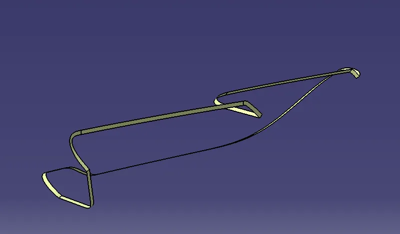
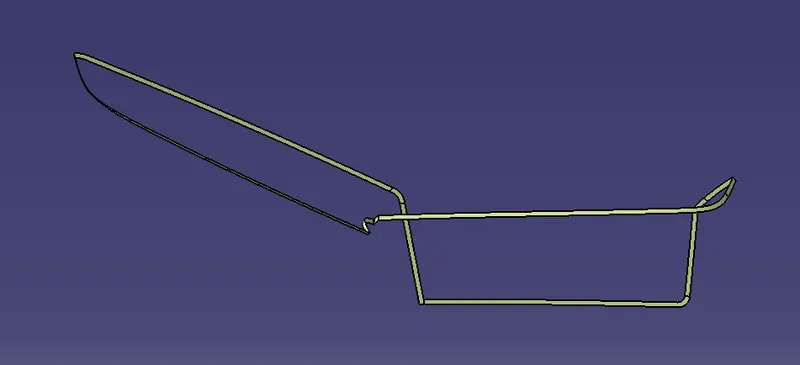
Creation of Flanges:
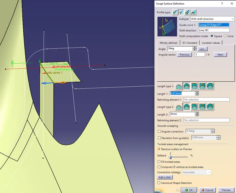
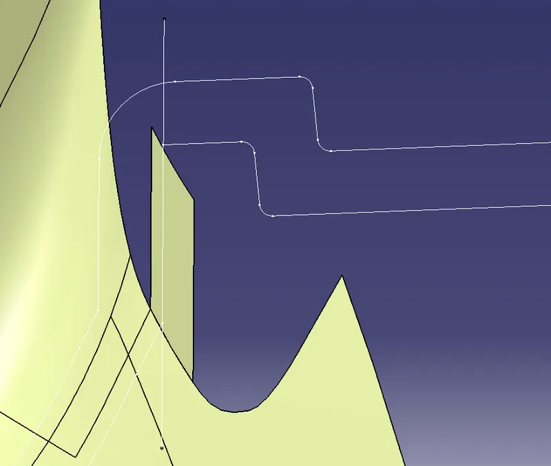
1.To create the Flanges,Extract the Boundary of Class A using Multiple Extract option.Create a line using Point-Point by Line Definition by selecting the two points on Master section as shown.
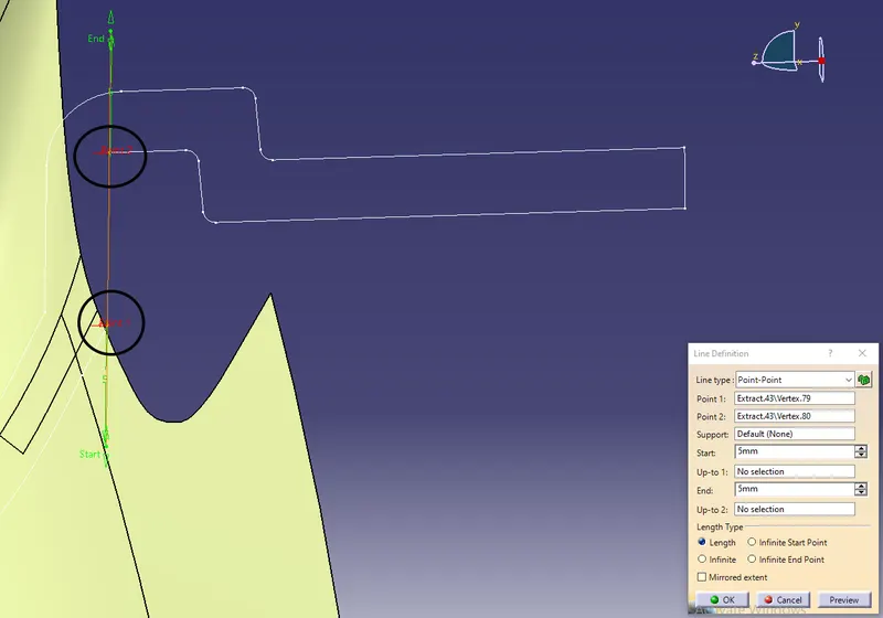
2.Use the Curve smooth option to smooth the extracted boundary and then using the Sweep option create the Flange by Sweep : Profile type - 2 ,Subtype - with draft direction,Guide curve - Boundary, Draft Direction : select the line created.
3.Create the remaining surfaces in same procedure.
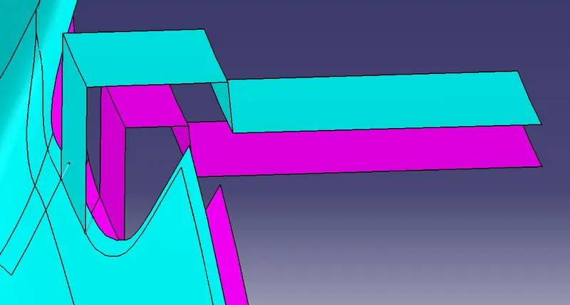
4.Compare with the Master section and Class A of the Flange,change as per the Master section.Trim the Flange with Class A.Same procedure to create the Flange at the required places.
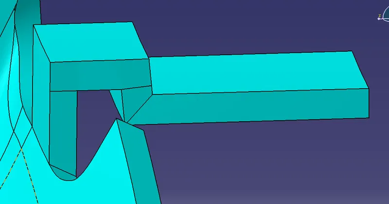
5.Offset the Flanges to 2.5mm to trim it with the B Surface.Extrapolate the B Surface if the Flanges were not intersecting with the B Surface.
Creation of Dog house:
1.Draw the profile sketch of the dog house and extrude it in both directions by Extrude option : Profile - Line and Direction in Generative Shape Design.
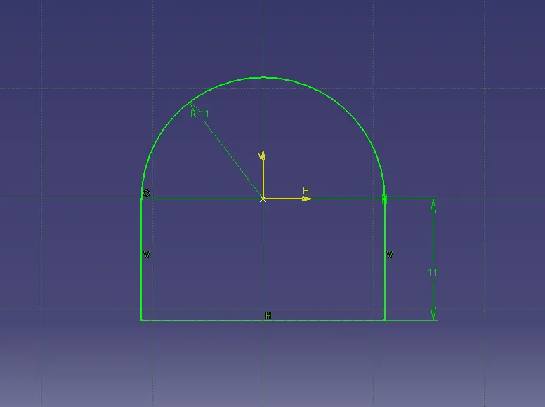
2.Extract the boundary of the wall on one side and extrude it to create a top wall and then trim it.
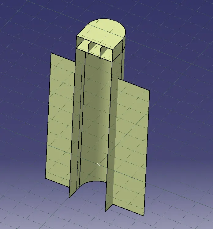
3.Thicken the surface in Part design to a wall thickness of 0.7 T where T is then main wall thickness.
4.Draft the side walls inside and outside with an Angle: 0.5degrees and Faces: selecting the faces to draft and the neutral element as a base face and the Pulling direction.
5.Now create the inner trim for the Dog House by offsetting the side walls as the ‘C’ should be 40% to the Main wall thickness and offset the B surface in the region of dog house upwards as the ‘B’ distance from the B Surface is 3-6mm for Dog House.
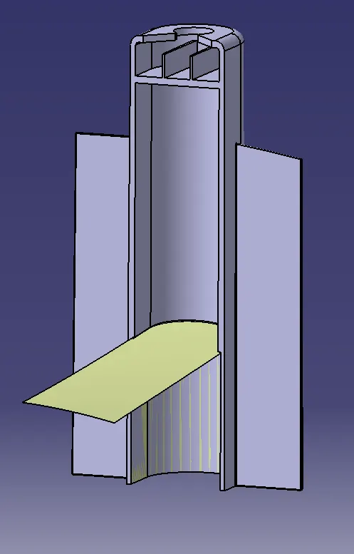
6.Now trim the surfaces to create the slot and split it with the Dog house using Split option in Part design and fillet the edges to a radius of 0.25 T.
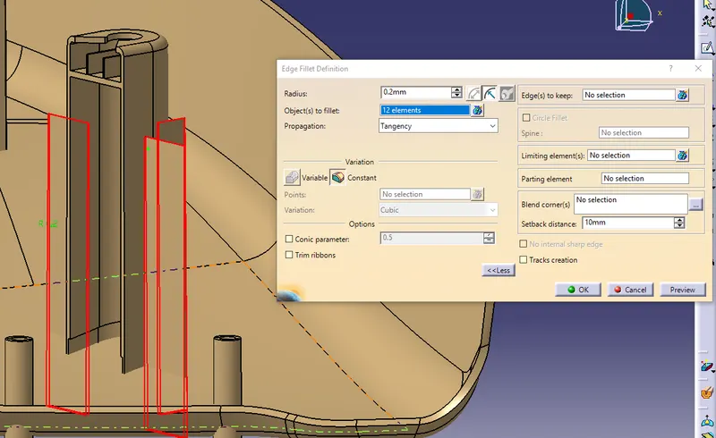
7.Create the dog houses where these are needed.
Creation of Push clip:
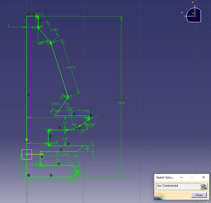
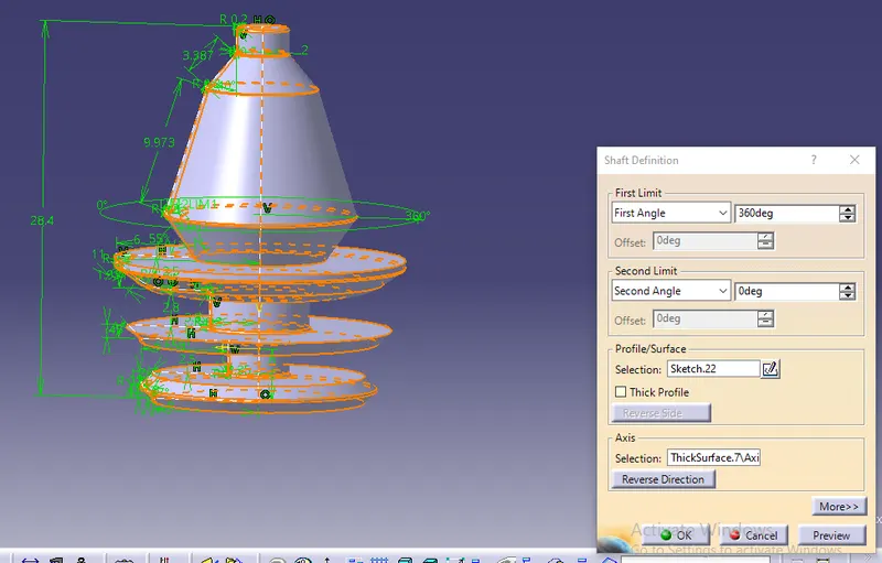
Create the profile of the Push clip in sketch and using the Shaft command make it solid by selecting the Profile and direction of rotation.
Creation of Heat stakes:
Create a circle of 8mm diameter in XZ plane in a sketch and Pad it in Part design.In Pad,click the Thick command and add thickness inside of 2mm as for heat stakes Outer and inner diameter should be 8mm and 6mm respectively and distance between two heat stakes should be 60-70mm.
- The gap between the heat stake hole and heat stake should be 0.5mm gap.
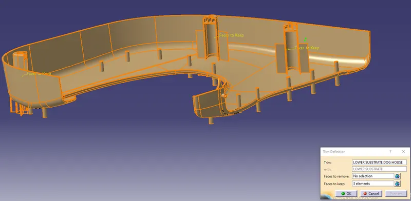
- Union trim the dog house and heat stakes with the Main component
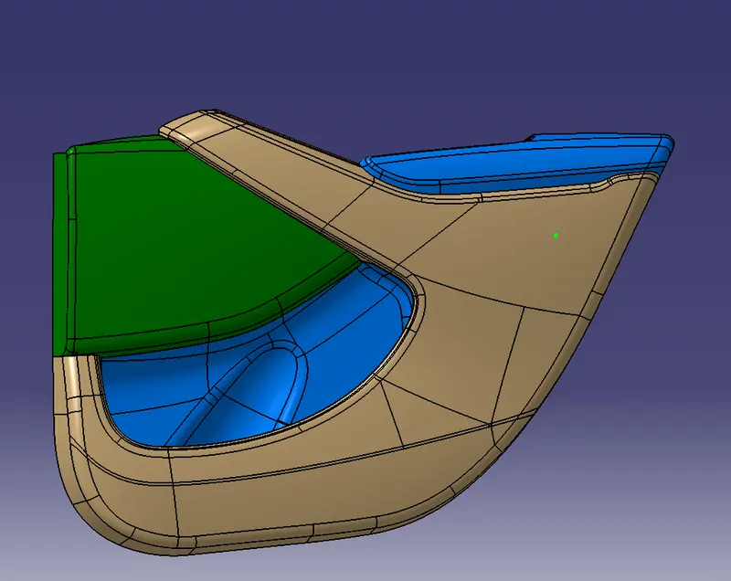
SOLID COMPONENT:
DRAFT ANALYSIS:
ARM REST
MAP POCKET
LOWER SUBSTRATE:
DOG HOUSE:
RESULT:
Designed and developed a Car Side Door Interior Panel from the given Class A surface.Attached the Engineering Features like Heat stakes, Dog houses and Push Clips.