Week - 4
1.
AIM:To implement control logic of a “washing machine” using Stateflow.
Objective:Implement control logic of a washing machine using Stateflow as per given sequence:
- If the power supply is available, the system gets activated
- If the Water supply is not available, stop the process & indicate through LED
- Soaking time should be 200s followed by Washing time of 100s.
- Then rinsing happens for next 20s & dryer runs for 50s
Process:
1.In Simulink, create a Chart block and open the chart block.
2.Using the State block create a Control logic for the Washing machine.
3.The Control logic of the Washing machine should be
- If the power supply is available, the system gets activated
- If the Water supply is not available, stop the process & indicate through LED
- Soaking time should be 200s followed by Washing time of 100s.
- Then rinsing happens for next 20s & dryer runs for 50s.
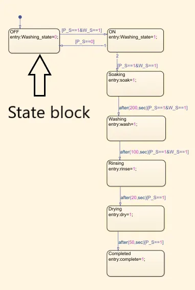
4.The control logic is created by Stateflow.
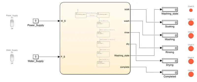
5.After creating the control logic for washing machine in chart block,using the Constant blocks create 2 blocks outside of the Chart block which are for "Power Supply(P_S)" and "Water Supply(W_S)" with the constant values of "1" and "0" which means 1-Turns On the system and 0-Turns Off the system.
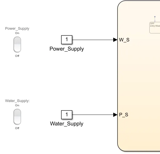
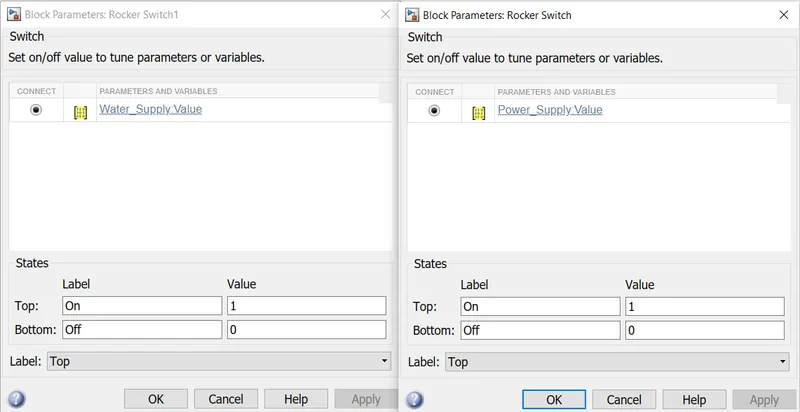
6.Using the Rocker switch block from the library connect the switch blocks with the constant blocks so that the switch acts as gate.
7.Create the Display blocks for every state of Washing_state,SoakWash,Rinse,Dry and Process Completion so that the display shows the process state of completion.
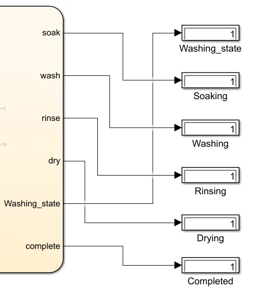
8.Connect the Lamps to every Display so the Lamp indicates the Process state of completion.
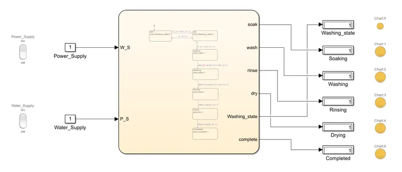
9.The time period indicates the time required for that process so after the time period completes the state moves to the next state.
10.Stop time:400 sec
Symbol Pane:
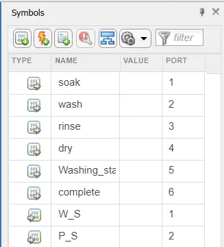
Used Blocks:
Chart:A finite state machine is a representation of an event-driven (reactive) system. In an event-driven system, the system responds to an event by making a transition from one state (mode) to another.
Constant:The Constant block generates a real or complex constant value signal. Use this block to provide a constant signal input.

Rocker switch:The Rocker Switch block toggles the value of the connected block parameter between two values during simulation.
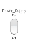
For example, you can connect the Rocker Switch block to a Switch block in your model and change its state during simulation.
Display:The Display block shows the value of the input data. You can specify the frequency of the display.
Lamp:The Lamp block displays a color to indicate the value of the input signal. You can use the Lamp block with other Dashboard blocks to build an interactive dashboard of controls and indicators for your model.
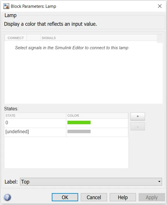
When Power and Water Supply is On Lamp turns Green.
When Power and Water Supply is Off Lamp turns Red.Even if any either of Power supply or Water supply if Off the system will not start and it shows red.
2.
AIM:Make a Simulink chart for the “Gear shift” logic as per below conditions:
Speed Range(kmph) Gear
0 to 15 1
16 to 25 2
26 to 40 3
41 to 60 4
Above 61 5
Process:
1.In Simulink, create a Chart block and open the chart block.
2.Using the State blocks create a gear shift logic with rspect to speed.
3.
Speed Range(kmph) Gear
0 to 15 1
16 to 25 2
26 to 40 3
41 to 60 4
Above 61 5
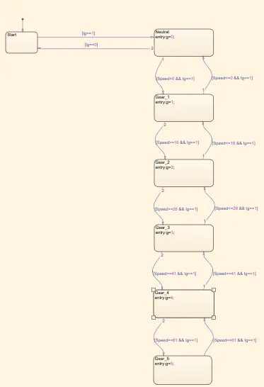
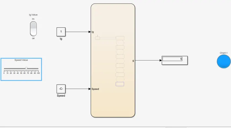
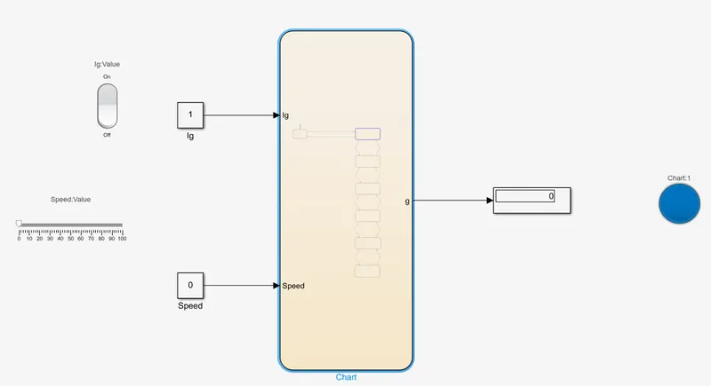
4.In chart block create a state flow of gear shift when Ignition Turned On and with increase in speed change in gear 1-5.
5.As Speed>0 will be in neutral create a block so when speed comes to 0 it shifts to neutral.
6.After creating the control logic for gear shift in chart block,using the Constant blocks create 2 blocks outside of the Chart block which are Power supply(Ig) and Speed with the constant values of "1" and "0" which means 1-Turns On the system and 0-Turns Off the system.
7.Use the Rocker Switch as a Power switch and connect to Ignition block which controls the Power supply ON-OFF.
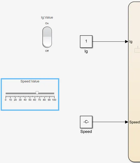
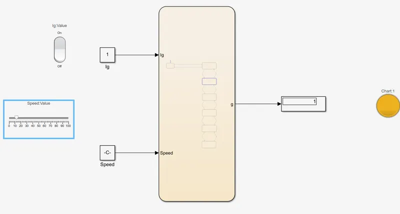
8.Use the Slider block from the library to control Speed and connect to the constant block.So by changing Knob in the Slider block the Speed changes.
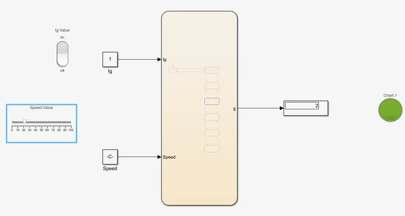
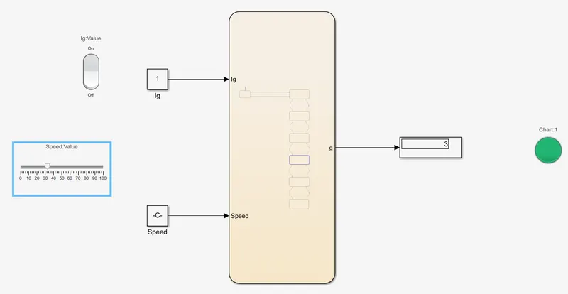
9.Connect the display as output to show the gear state and connect a Lamp to Display to indicate the color of gear state.All 5 different colors indicate different gears.
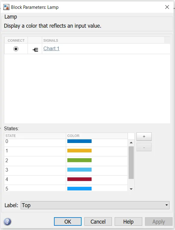
10.Stop time:inf(infinite) as the gear shifting process is a long time process.
Symbol Pane:
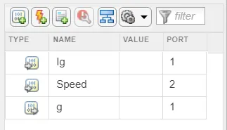
g:Gear-Output
Logic:
Ig-notation of Ignition,Ig==1 means Power Turns On and Ig==0 means Power Turns Off.
At Speed<=15 the gear will be 1st and at Speed>=16 the gear shifts to 2nd.
At Speed<=60 the gear will be 4th and at Speed>=61 the gear shifts to 5th.
Similarly at different speeds the gear shifts with respect to speed.
Used Blocks:
Chart:A finite state machine is a representation of an event-driven (reactive) system. In an event-driven system, the system responds to an event by making a transition from one state (mode) to another.
Constant:The Constant block generates a real or complex constant value signal. Use this block to provide a constant signal input.
Rocker switch:The Rocker Switch block toggles the value of the connected block parameter between two values during simulation.
For example, you can connect the Rocker Switch block to a Switch block in your model and change its state during simulation.
Display:The Display block shows the value of the input data. You can specify the frequency of the display.
Lamp:The Lamp block displays a color to indicate the value of the input signal. You can use the Lamp block with other Dashboard blocks to build an interactive dashboard of controls and indicators for your model.
Slider:The Slider block tunes the value of the connected block parameter during simulation. For example, you can connect the Slider block to a Gain block in your model and adjust its value during simulation.
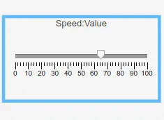
In Neutral(Speed=0)
At 1st Gear(Speed<=15)
At 2nd Gear(Speed>=16)
At 3rd Gear(Speed>=26)
At 4th Gear(Speed>=41)
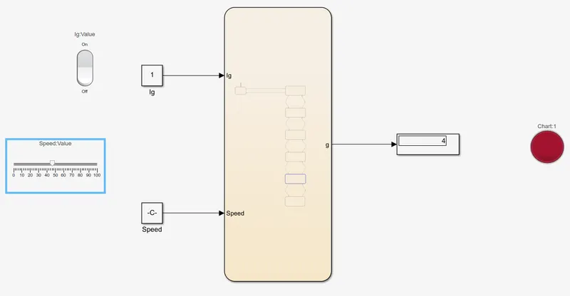
At 5th Gear(Speed>=61)