Fender Design Challenge
AIM:
To create the Drip area mount for front fender in the car by following the master section and also create the Sill mount, Bumper Mount and A-Pillar mount according to the Engineering standard.
FENDER:
Fender is the part of an automobile, motorcycle or other vehicle body that frames a wheel well. Its primary purpose is to prevent sand, mud, rocks, liquids from being thrown into the air by the rotating tire.
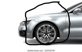
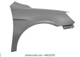
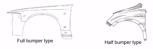
Fenders are of two types:
1.Full Bumper type
2.Half Bumper type
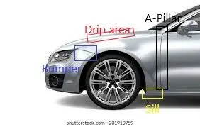
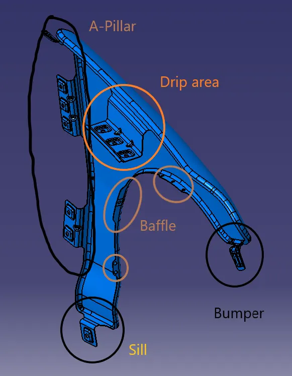
Fender mainly mounts on five area:
1.Sill
2.Drip area
3.Bumper
4.A-Pillar
METHODOLOGY:
1.Split the extra surface of the fender as per Master section.
2.Split the surface by using the connect curves to create the mounts.
3.Create the Drip area mount by following the Master section.
4.To create the drip area mount for front fender the consideration are:
- From the cowl point to towards the front side the distance should be 200mm.
- From the front head light point to towards the back side the distance should be 150mm.
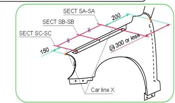
5.The remaining distance can be used to create the drip area.
6.Create the remaining mounting points with our own design which should follow the Engineering standards.
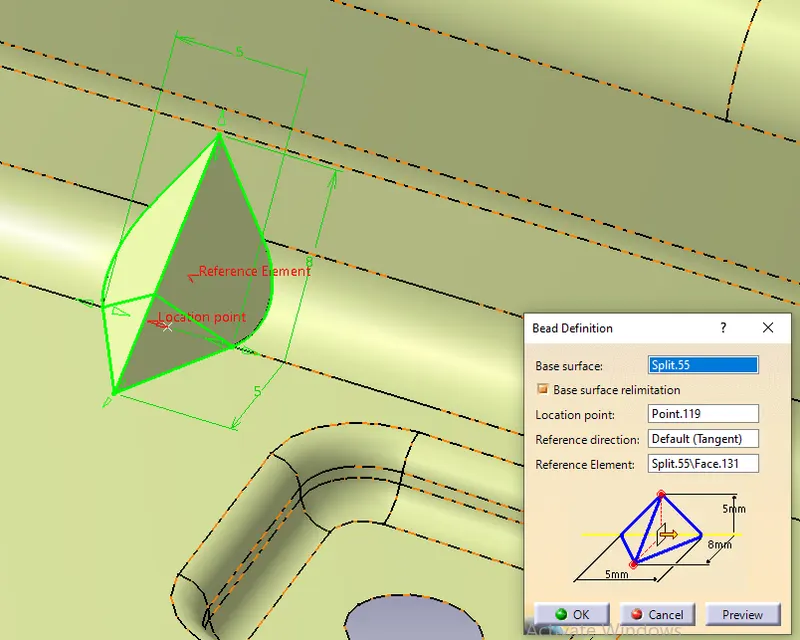
7.Create the Beads at the fillets to strengthen the mounts.
PROCEDURE:
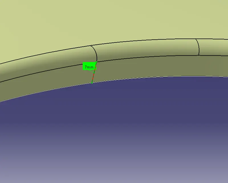
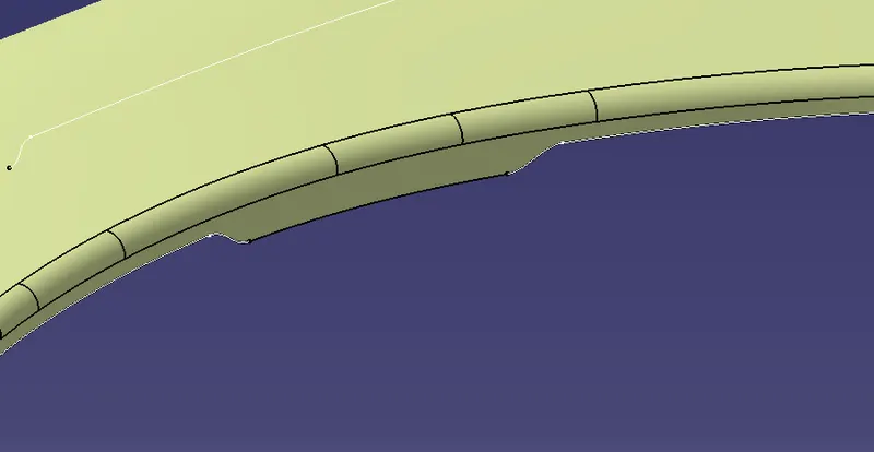
1.Split the surface of the fender at a distance of 7mm by extracting the surface edge using Multiple Extract and offsetting the curve using the Parallel curve to a distance of 7mm as shown.
2.As the surface has open boundaries,Extract the skin and side wall and join the surfaces and then split to 7mm.
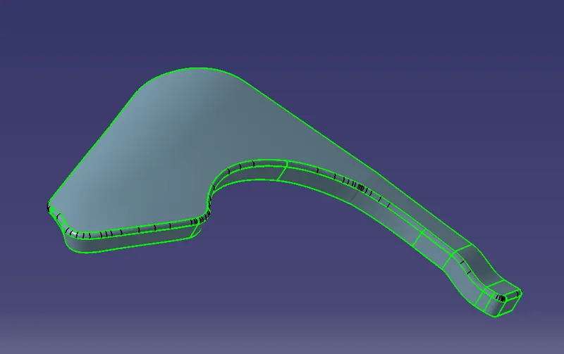
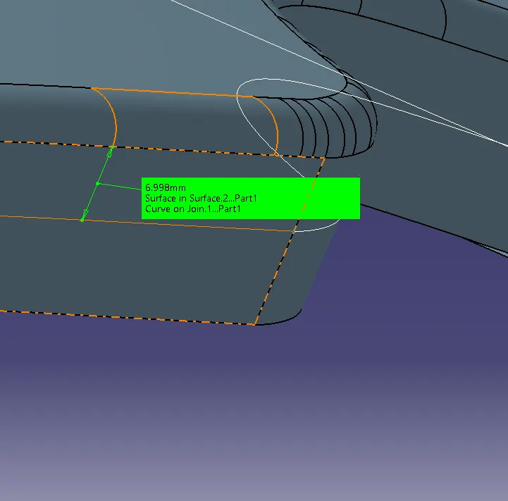
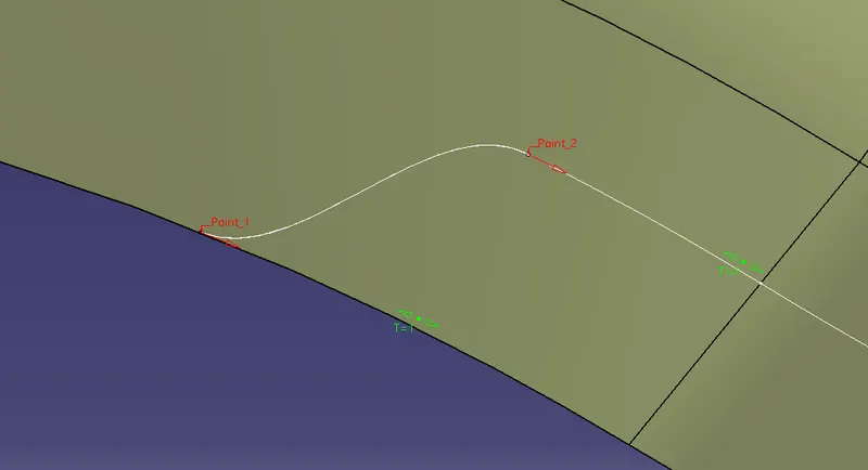
3.Create the mount area by offsetting the boundary line to 4mm and creating the points on two boundaries and then using the Connect curve command (White lines) select the two points and support to the points as shown and then Split the surface.
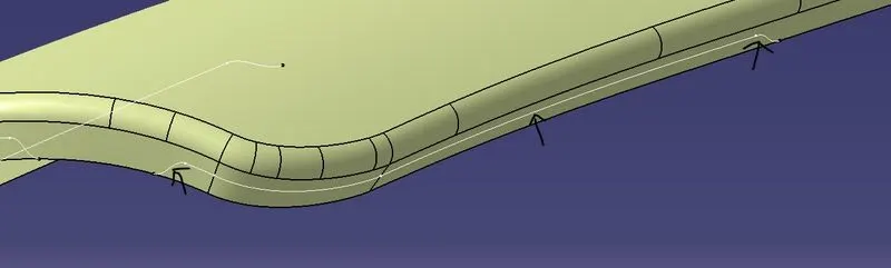
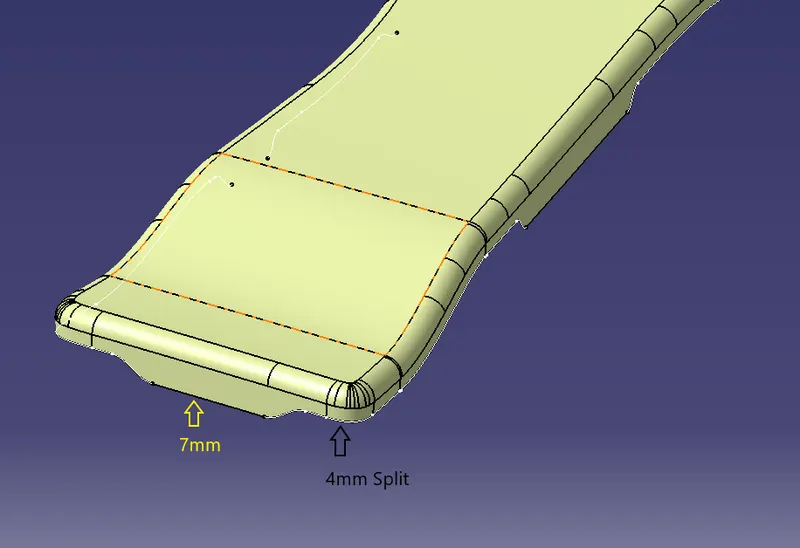
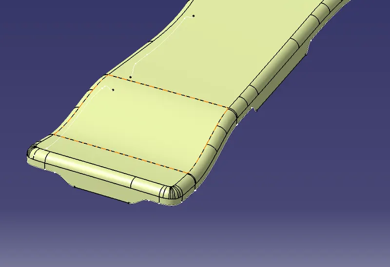
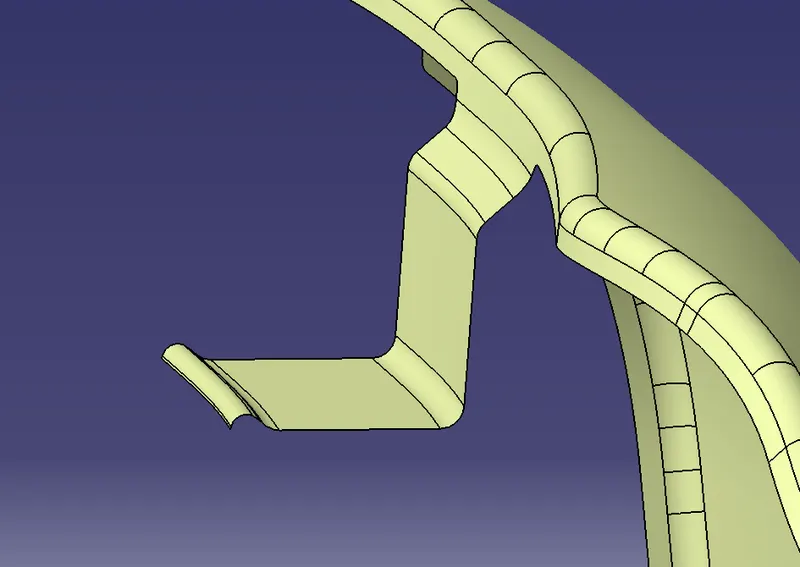
4.Create the Drip area using the Sweep option and then fillet the edges by following the master section and then create the embossments on the surface downwards as shown.
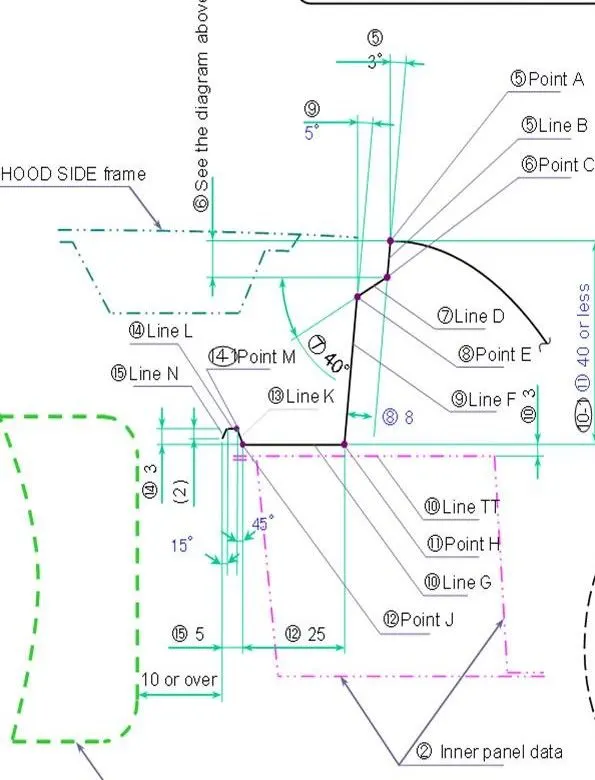
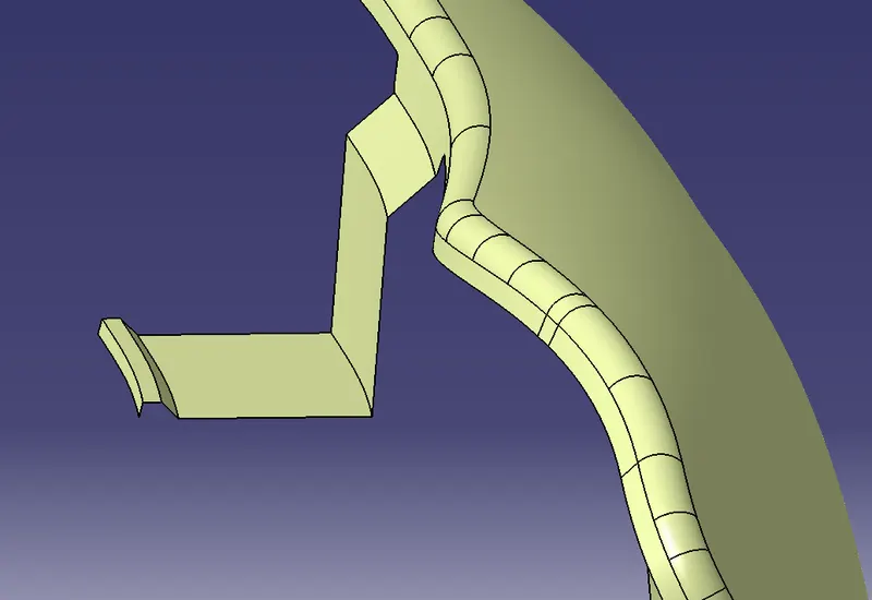
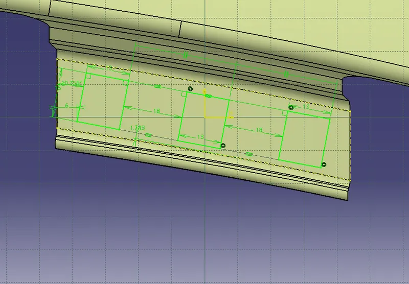
5.To create the embossments first create the sketch on the surface and project the sketch on to the surface and then split the surface with the projected sketch.
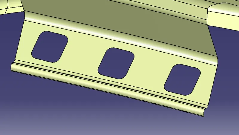
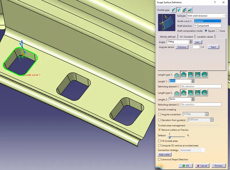
6.Using the Sweep option create the surface downwards with an angle to clear the draft angle and then offset the surface to 2.5mm distance downwards then trim it to 2.5mm to create the embossment using the Trim option and then fillet the edges.Create the holes on the embosses where there should be flat surface of 5mm around the hole.
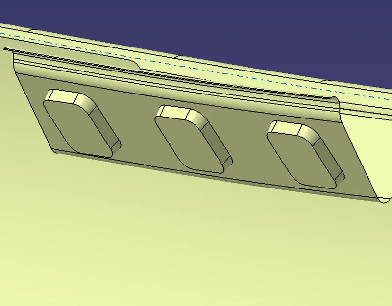
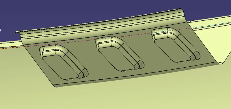
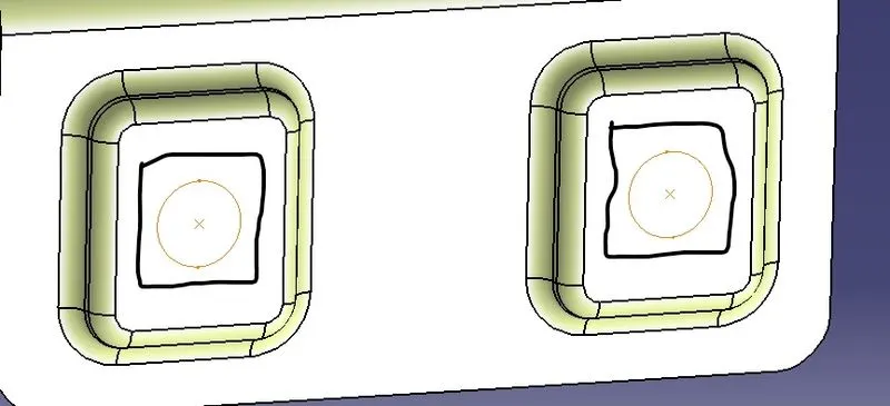
7.Create the mounts for Sill,A-pillar,Bumper and Baffle areas with engineering standards.
8.Create the embossments for the Sill,A-pillar,Bumper and Baffle areas following the same procedure and fillet the edges.
A-pillar mounts
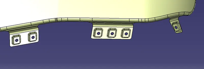
Sill mount
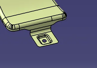
Bumper mounts
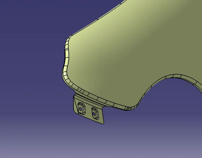
Baffle mounts
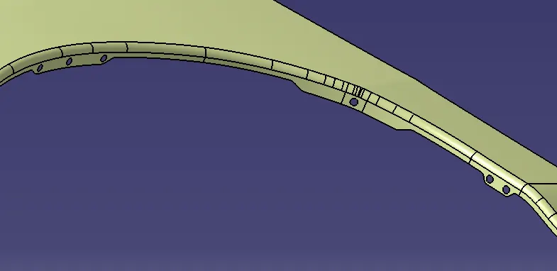
9.Create the ribs/beads to strengthen the fillets using the Bead option by creating a point on the curve and then selecting the point in the Bead command and fillet the edges.
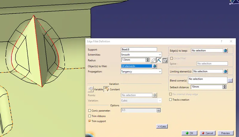
A-pillar mounts
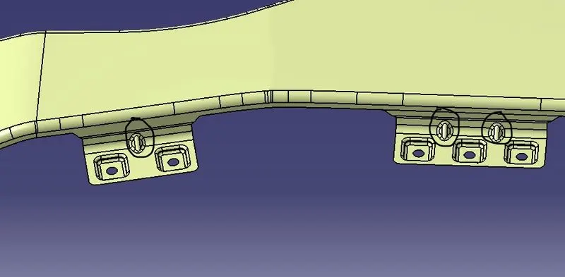
Bumper mounts
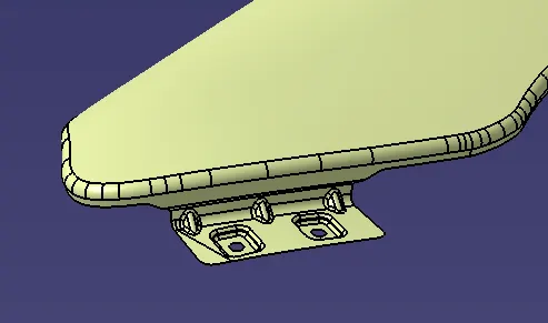
Drip mounts
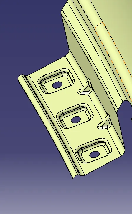
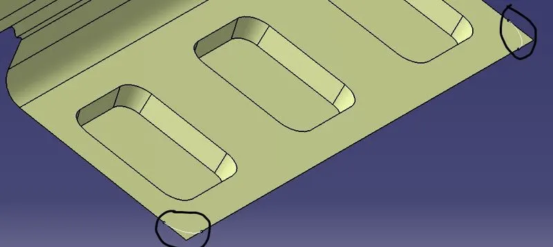
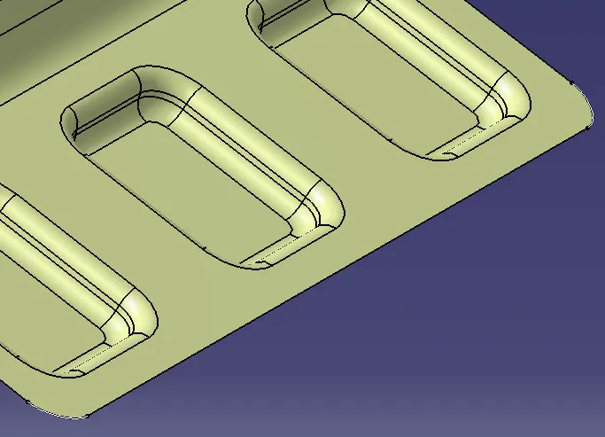
10.Remove all the sharp edges by creating the fillets by using Connect curve command and split the surface with the curves.
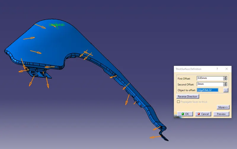
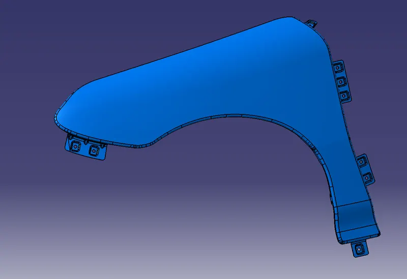
11.Thicken the surface with 0.65mm.
RESULT:
Created the mountings for Drip, Sill, A-pillar,Bumper and Baffle areas as per the Master section and design rules.