Assignment 3
AIM:
To run the simulation and compare the simulation of Shell element formulation with two cases(with properties and without properties).
ABSTRACT:
To run the simulation in hypermesh in Radioss block by assigning the required values and then to run the crash animation in Hyperview block and Plotting graphs in HyperGraph 2D block with 2 cases and then comparing 2 cases.
METHODOLOGY:
- Hypermesh>Analysis>Radioss to convert the file format to Radioss.
- Hyperview to run the animation of crash into a rigidwall.
- HyperGraph 2D to plot the graphs.
PROCEDURE:
CASE 1:
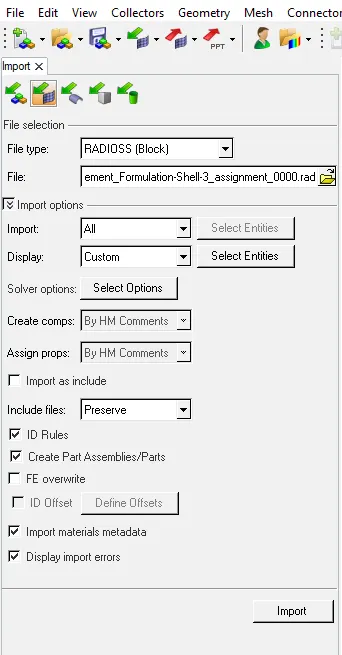
1.Import the Starter file(0000.rad) from Solver deck.
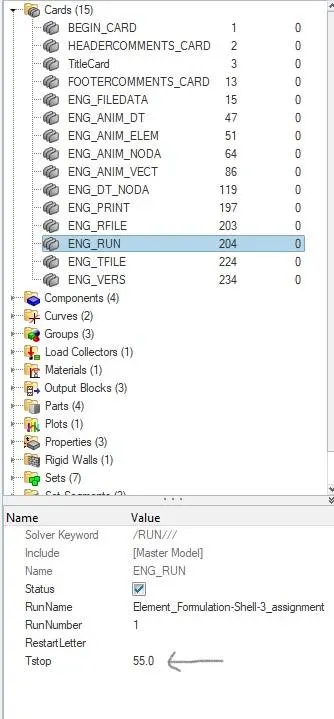
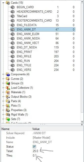
2.Assign the value of Tstop as 55ms in Cards>Engine Run given in the question and in Engine-Animation-DT,Tstart is given minimum as 25 and Tfreq is 0.1.
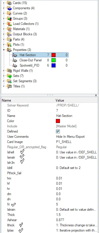
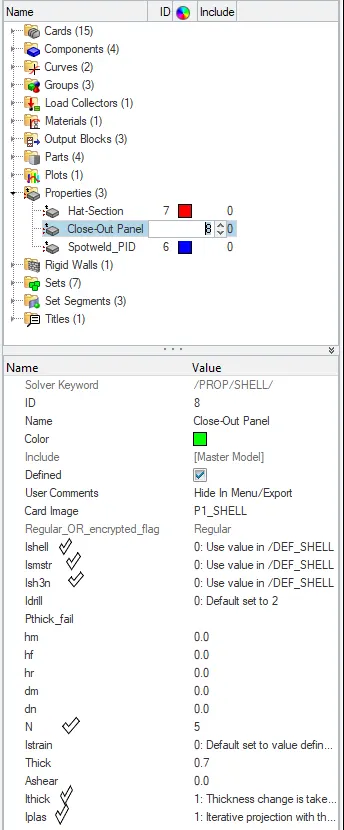
3.Check that the Property Values in Properties where Card Image should be common in either of the 3 properties should be default values.
4.Check these values in the Property of common Card images:
- Ishell =0
- Ismstr=0
- Ish3n=--
- N=5
- Ithick=1
- Iplas=1
5.In Analysis>Radioss,give the input file as (0000.rad) file and ‘tick’ include connectors which keeps in connected the surfaces and option as ‘-nt 4’ and click ‘Radioss’.

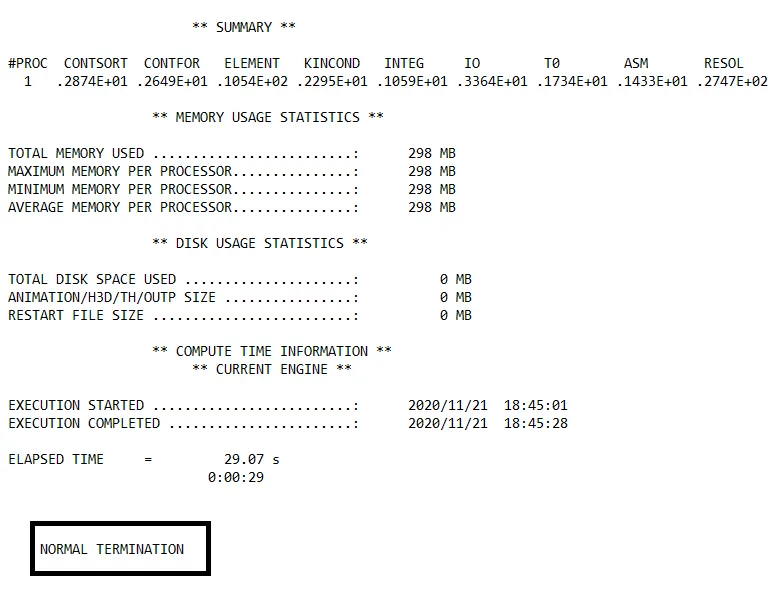
6.It runs the base simulation and gives the error file as (0001.out) file which consists of mass error,energy error,external work and at the end of file it should indicate ‘NORMAL TERMINATION’ which indicates successful simulation without any errors.
7.Now change the Client selector (ToolBar) from ‘Hypermesh’ to ‘HyperView’ to create the animation of crash.Upload the file (h3d) in ‘Load model and results’ of case 1 and ‘Apply’.Save the animation video.
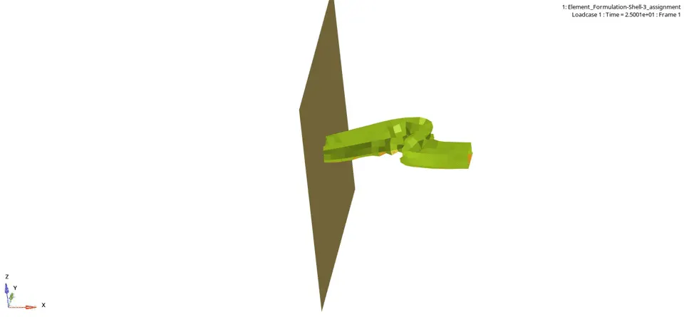
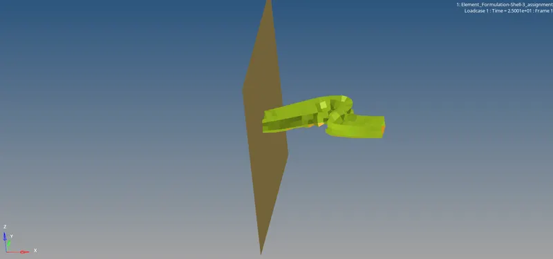 THIS IS THE CRASH WHICH STARTED AT 25ms
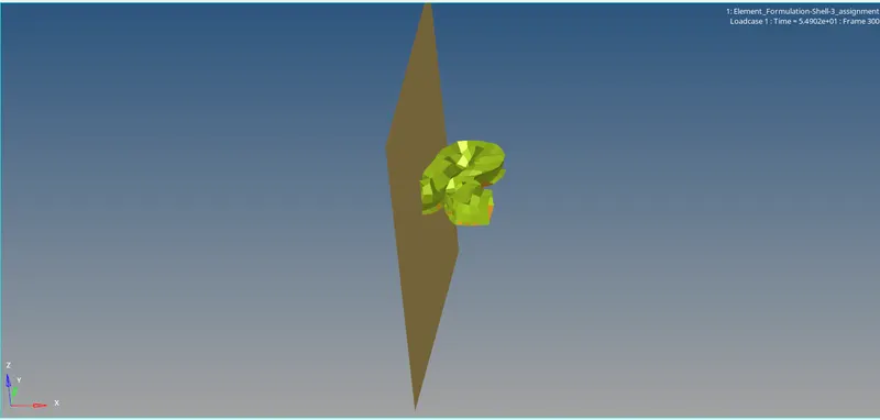 THIS IS THE CRASH WHICH ENDED AT 55ms
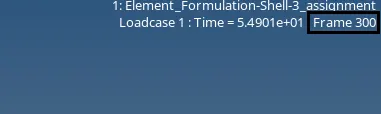
8.Frame=300 indicates that the 30 animation frames for 0.1 millisecond.
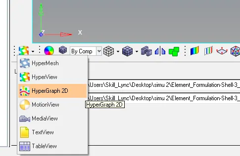
9.Now change the Client selector from ‘Hyperview’ to ‘HyperGraph 2D’ where you need to plot the graphs which are given.
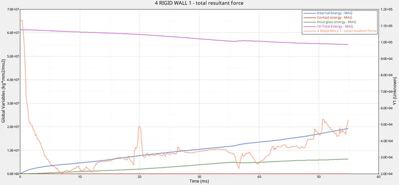
10.Plot the graphs for rigid wall forces, internal energy, hourglass energy, contact energy, total energy of the simulations.
CASE 2:
1.Import the Starter file(0000.rad) from Solver deck.
2.Assign the value of Tstop as 55ms in Cards>Engine Run which given in the question and in Engine-Animation-DT,Tstart is given minimum as 25 and Tfreq as 0.1.
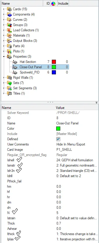
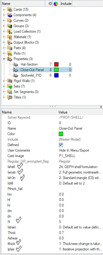
3.Assign the Recommended Property Values in Properties where Card Image should be common in either of the 3 properties.
4.Assign these values in the Property of common Card images:
- Ishell =24
- Ismstr=2
- Ish3n=2
- N=5
- Ithick=1
- Iplas=1
5.In Analysis>Radioss,give the input file as (0000.rad) file and ‘tick’ include connectors which keeps in connected the surfaces and option as ‘-nt 4’ and click ‘Radioss’.
6.It runs the base simulation and gives the error file as (0001.out) file which consists of mass error,energy error,external work and at the end of file it should indicate ‘NORMAL TERMINATION’ which indicates successful simulation without any errors.
7.Now change the Client selector (ToolBar) from ‘Hypermesh’ to ‘HyperView’ to create the animation of crash.Upload the file (h3d) in ‘Load model and results’ of case 1 and ‘Apply’.Save the animation video.
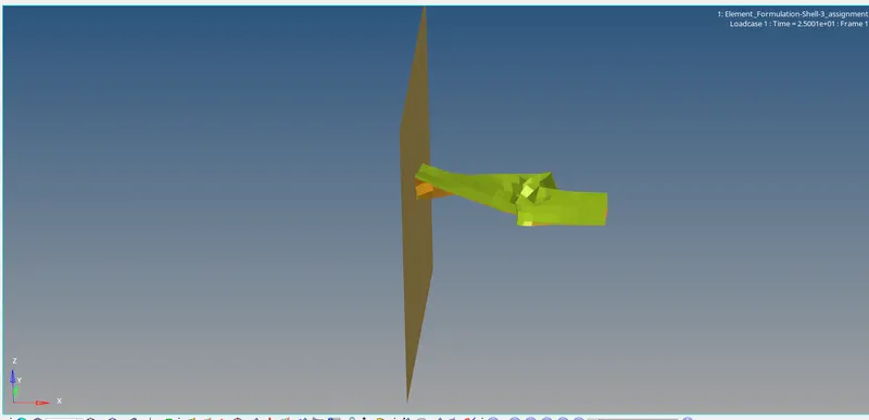 THIS IS THE CRASH WHICH STARTED AT 25ms
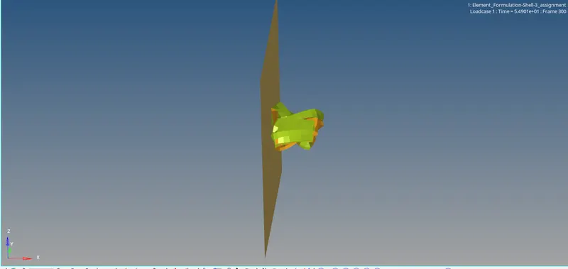 THIS IS THE CRASH WHICH STARTED AT 55ms
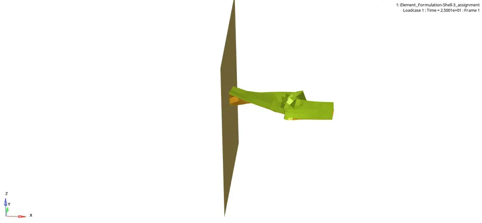
8.Frame=300 indicates that the 30 animation frames for 0.1 millisecond.
9.Now change the Client selector from ‘Hyperview’ to ‘HyperGraph 2D’ where you need to plot the graphs which are given.
10.Plot the graphs for rigid wall forces, internal energy, hourglass energy, contact energy, total energy of the simulations.
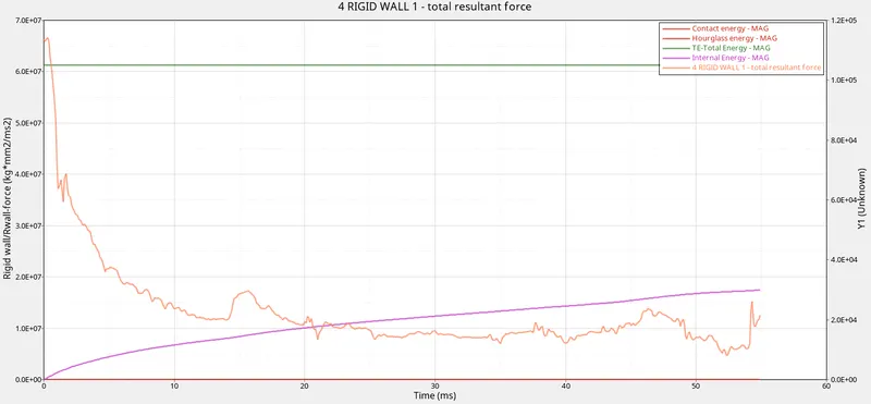
COMPARISON:
CASE 1:THIS IS THE GRAPH WITHOUT ASSIGNING PARAMATERS Of Ishell,Ismstr,Ish3n,N,Ithick,Iplas.
 START OF CYCLE
 END OF CYCLE
CASE 2:THIS IS THE GRAPH AFTER ASSIGNING PARAMATERS Of Ishell,Ismstr,Ish3n,N,Ithick,Iplas.
 START OF CYCLE
 END OF CYCLE
Changes compared to case1 and case2:
- There is a change in graph of case 2 comapred to the graph of case 1 due to change in properties in case 2.
- There is a drastic change in Hourglass in case 2 compared to case 1 due to change in its Ishell property.
- In case 2 Hourglass became constant as Ishell=24 is a QEPH element and also uses Physical Stabilization method.It adds artificial stiffness to the component and stabilizes/control deformation.
- Mass error remains constant in both case 1 and case 2.
- There is change in Time step where time step decreases in case 2.
- Reduce in energies error.
- Stabilization of Hourglass deformation error in case 2.
HOURGLASS:
Reduced integration leads to non-physical zero energy modes called HOURGLASS MODES.
CAUSES:
It is a condition where node is moving and stress is not recording.That stress will not develop any force and also breaks time step process.
It is the energy where neither absorbed energy nor reflective energy can't be predicted.
Reduced Ishell property increases the deformation in Hourglass due to reduced integration.
STEPS TO AVOID:
HourGlass can be controlled by using 2 methods which stabilizes the deformation by adding artificial stiffness.
1.Perturbation Method(Viscous)-Q4
2.Physical Stabilization Method-QEPH
The recommended Ishell value is 24-QEPH element due to its low cost and accuracy.
RESULT:
Completed the simulation and Plotted the graphs for internal energy,hourglass energy,Contact energy,Total energy and Rigid wall forces.
CONCLUSION:
Change in Parameters in Properties can change the Energy Values and Time Period.
Parameters change with respect to the type of material.