Wiring harness design in CATIA V5 - 3D modeling Week 7 Challenge
The challenge is to flatennen the routing I did in Week 4 Challenge which is same as the sketch shown above.
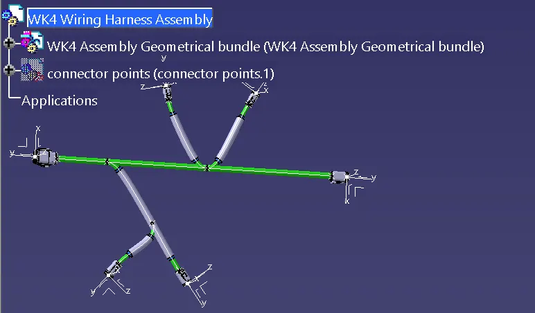
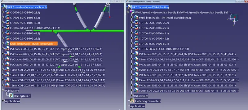
First I opened the product file wk4 challlenge Assembly Geometrical bundle. Saved it in a new folder created Wk7 Challenge. All the supporting connector part files also copied in this new folder. The product or assembly looked as below.
Next I created a new product file named it "Wk7 Flatenning of Wk4 Routing" and saved in the same folder. The week 4 routing file is already open and saved.
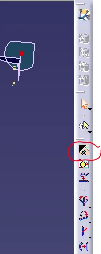
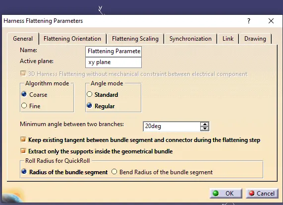
I change the platform and open "Electrical Harness Flattening". The first thing is to set the parameters. I selected the command shown as marked in the picture below "Harness Flattening Parameters". A new window opens in which we have to select the parameters.
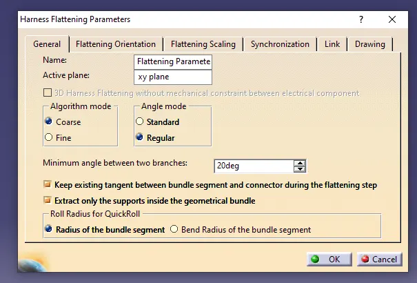
In the above window the settings will be
Algorithm mode- Coarse
Angle mode-Regular
Minimum angle between two branches- set to 20deg
select-keep existing tanget between bundle segment and connector during the flattening step
select-Extract only the supports inside the geometrical bundle.
select-Radius of the bundle segment.
Then I select OK and new product file will be created and the name I created and saved "Wk7 Flatenning of Wk4 Routing".
Next I tile the window vertically. Since two files are open both file will be opened parallel
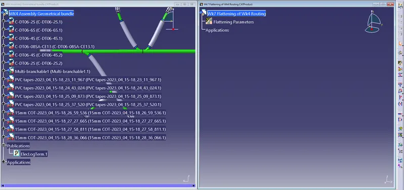
Some of the commands get active. Next I select the command Extract and select the file Wk4 assembly Geometrical bundle. This file gets a extension and the new file name will appear as Wk4 Assembly Geometrical bundle_Ehf. I verify if all the routing branches and all connectors are imported, and find that all are imported and so continue.The window of routing file will close and new file will remain open. This file is saved and the next commond below the extract is Flatten. I select this command.
I Select the command Flatten and a new window opens
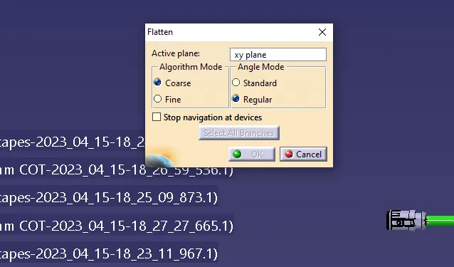
In this I retain the plane XY plane. We can select any plain or even one of the face of the connector can be selected as reference plane. Once the plane is selected it will ask for select branches. I select one of the branch and the option "select all branches" highlits and I select this option instead of select each individual branch. Since all the branches are connected every thing gets selected. I press ok with other option remaining same.
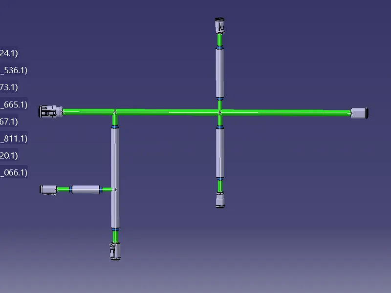
I get the straightened view of the electrical routing as seen below.
Next step is to create a new Drawing file with ISO as standard settings and A0 as the sheet size, Landscape as the view and select OK.
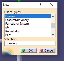
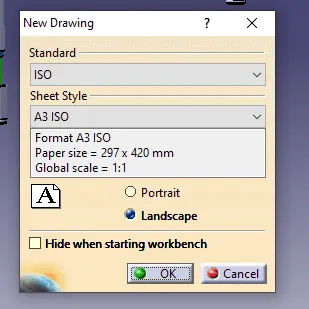
New screen opens which is a drawing sheet and I save the file as Wk7 Flattening of Wk4 routing. After saving I have to place the flatened routing on the sheet.
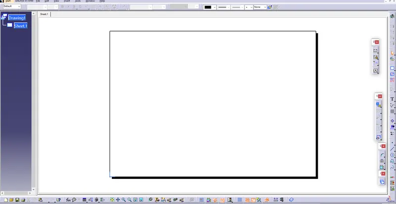
There will be only on view to be placed which shows all the parts and routing in flat view
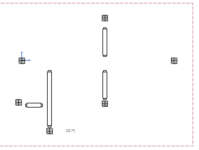
This picture above is what I get on the drawing sheet by placing the front view. This show some settings is required to get all the data on the drawing sheet. This setting is in drawing environment. So by right click of the mouse button on the border of the drawing a window opens and In the window I select properties. One more window opens as seen below
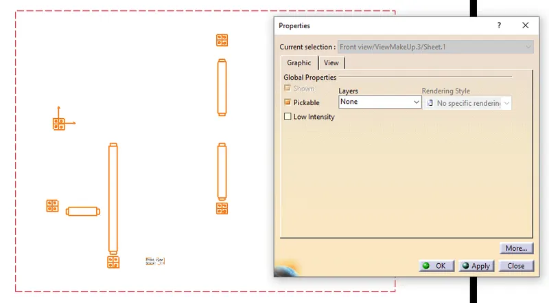
There are two options Graphis and View. In graphic there is no setting so I select View option and window changes
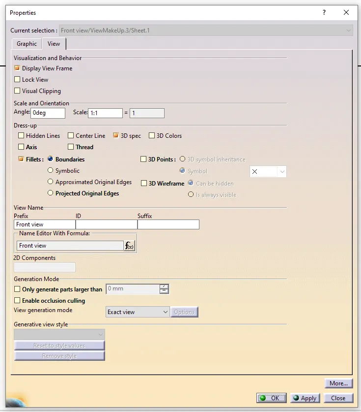
In this window I select the options as mentioned below
Visualization and behaviour
In this already the option Display view frame is selected by default and so I retain. The other two options are not selected and go to next Scale and Orientation. In this no options are changed angle is 0 and scale is 1:1.
Next option is Dress-up. Hidden lines, centre line, axis, thread are not selected. 3D specs, 3D colours is selected. 3D colour selection is not compulsary. When selected it gives the 2D drawing the same colours used in creating 3D part and if not selected, all things on the drawing sheet will be in black and white. This will be useful when i create different colour for different branches as colour code. If electrical lines are set with colour code, then the same is reflected in 2D drawing will clearly give which lines is for what.
Next is Fillets which is selected and option Boundries is selected. 3D point, Symbols, approximated original edges, projected original edges are not selected. 3D wire frame is selected as this the main option which generated the wire bundle display in 2D drawing. When this option is selected this will lead to two other options Can be hidden and Always visible. I select always visible. The other options are left as it is. By selecting apply and OK the drawing view will change as seen below.
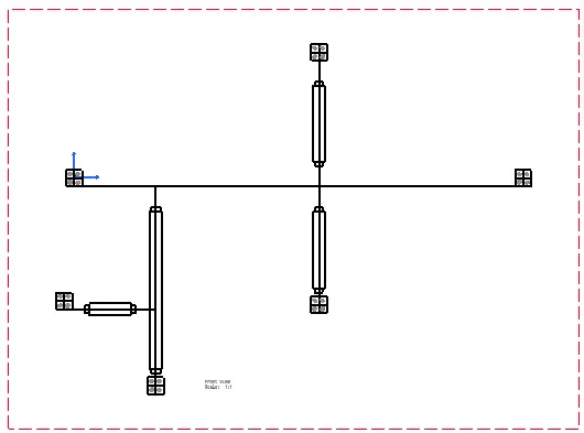
In the above view I see the routing is displayed in single line as I had selected in intial flatten paramaters setting, outer covering in double line and the same is displayed in the drawing. I see two double lines. One is insulation tape and the next is COT tubes. The connector is displayed by boxes. This really is not clear and do not specify or mention which type of connectors are used as all the connectors display is same. So I have to see different settings so that the connectors can be recognised in a better way.
The connector can be displayed as 3D models in which we can atleast recognise the type of connectors. To set the 3D display of connectors in 2D drawing there is a setting in the flattening parameters and so I change to catia product window from drawing window. There I select Flattening parameters which is already set and saved in structure tree. I select this and the below window opens
 3
3
I get this window and in this I go to drawing window.
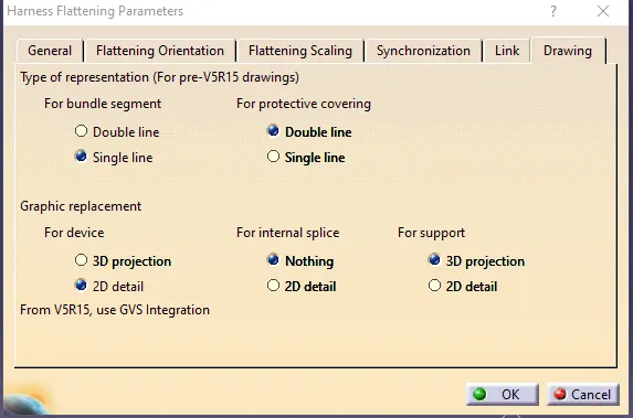
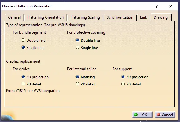
The option for the device which earlier set to 2D detail is now changed to 3D projection. This will show the connectors in 3D mode in drawing sheet. to check this I change the window to drawing and since the drawing cannot be updated, I delete the harness drawing and again add the front view in the drawing sheet. Below picture shows the final flattening drawing of wire harness.
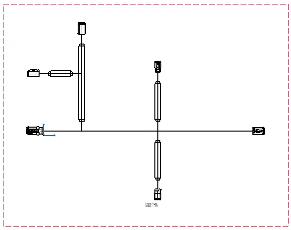
Next I will be displaying pictures of drawings with change in settings.
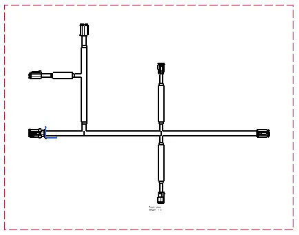
The picture above shows that the wire harness routing is shown in double line in small diameter, then insulation in slightly bigger and COT tubes in still bigger in diameter. This is when the option double line is selected in selection mode for bundle segment representation of flattening parameters setting, picture window is shown.
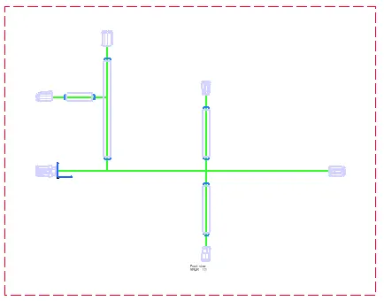
The picture above shows that the bundle segment is represented by single line, protective covering in double line and I have selected in drawing properties for display of 3D colours. So the 2D drawing has colour lines displayed the same used in creating routing.
With this the flattening challenge is complete I am attaching the folder in zip file.