Wiring harness design in CATIA V5 - 3D modeling Week 2 Challenge
Challenge is to download the electrical parts 3D from the manufacturer website and then using catia convert it into electrical part and define the connecting points.
Three links are provided for download.
By clicking the link Deutsch DT06-08SA we are directed to the the web page of TE and to the detail specification of the connector.
The specification says this is a connector housing female terminals made by DEUSTH and this is DT series plug connectors and this connector number is DT06-O8SA. In this web page we find the description of the connectors. This is a housing for 8pin, 4 pins in 2 rows and this houses female terminals and this is wire to wire connector. This can be used for both power and signal transmission.
The complete part specification with the size of the terminals, size of the connector, current carrying capacity, temperature limits, mating socket details, mating pin size are given and also mentions the standard it comply. There are seperate details provided with this product like Product drawings in tif file, CAD details in pdf, dxf, stp, iges formats and along with this it provides the product catalogue, product specifications and product certification approval agency details and standard of approval specification number.
All these details help us in selecting the terminal based on our requirement paramaters. Below the picture of the details in the web page.
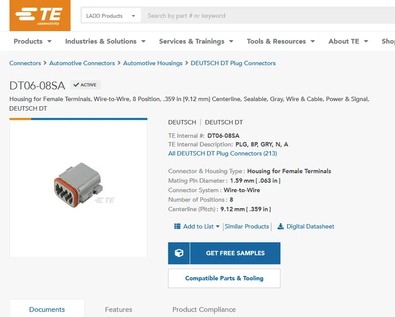

This connector type is Socket. From the above details by the supplier, it is easy to judge and select part as per our requirement.
For our job I downloaded the 3D stp file in a folder on the desktop. This was in a zip format and the file was extracted in the same folder. This step file was opened in Catia and saved as Catpart with the same name in the same directory. Next the catpart opened in part design.
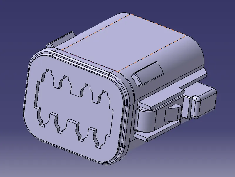
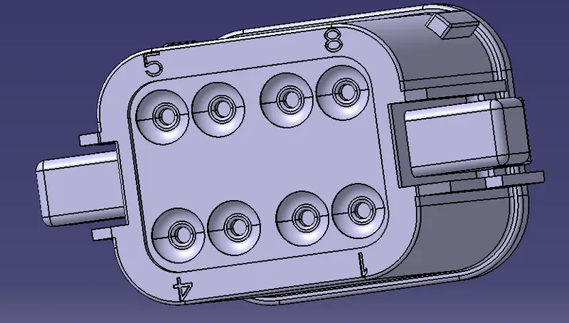
The down loaded 3D data part looks as seen in the above picture.
Now the job is identify and to create a point and an axis on the side and face of connector which is going to connect with face and point of mating socket.
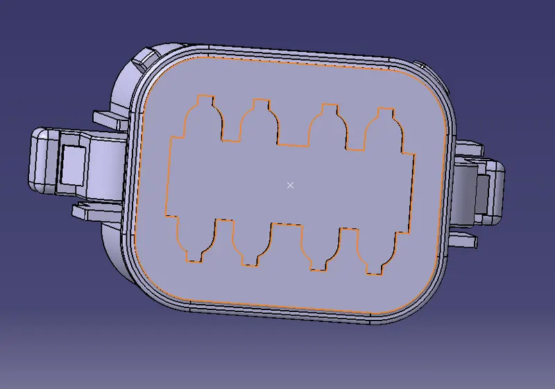
This face is identified as connector-socket connecting side. So a point on the face is created by taking two symmetrical points, centre point is created.
Then an axis system at this point is created.
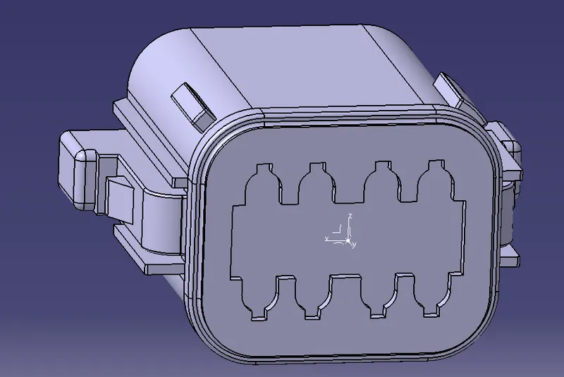
The general procedure followed is Y axis is directing outside from the face and X axis is horizantal or towards lock provision side, while Z axis is vertical. The Y axis is protuding outside. This is the standard followed for all the components marked as mating or assembly points which makes it easy during the time of assembly. With this marking the Catia electricaly assembly easily recognises that this connector will mate with other connecter on this face and other orientation as per the axis defined.
Next is the bundle entry or wire entry point. This is exactly is on the opposide face. We mark only centre point on the face as reference bundle entry point for calling it in assembly.
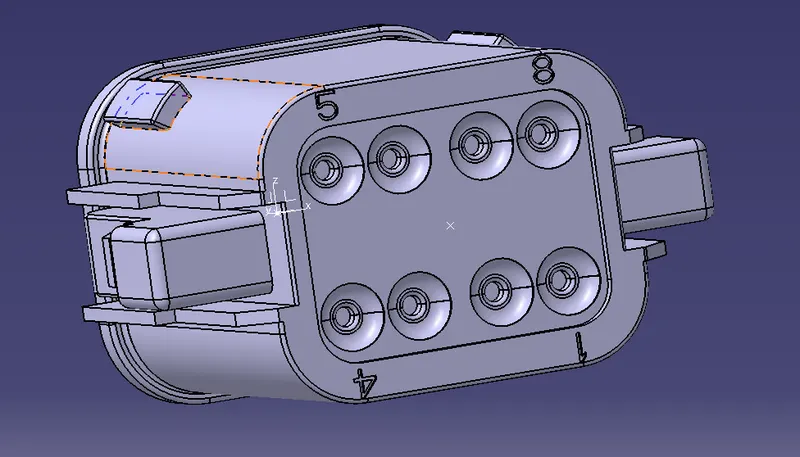
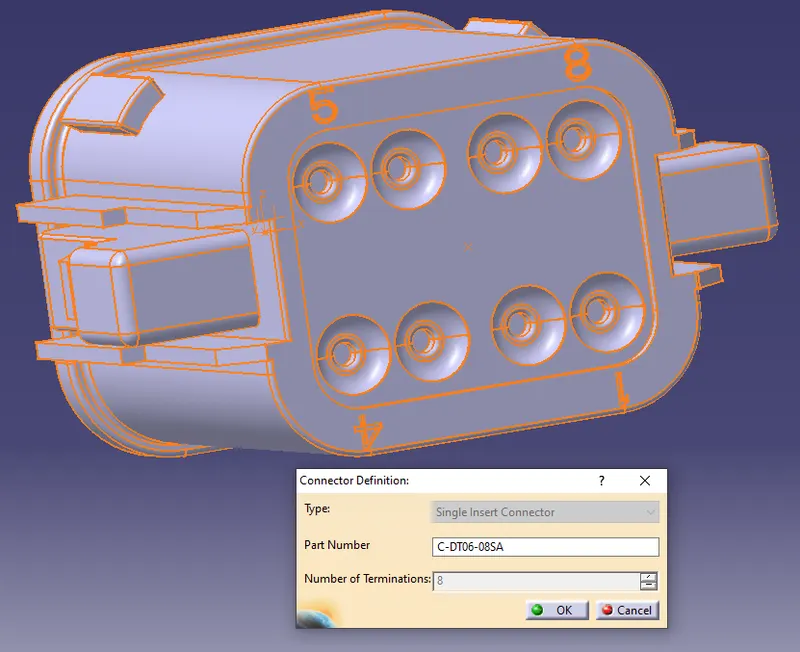
This completes the marking for the component. Now we shift to part design to electrical part design. Then this part is defined as connecter by selecting " Define Connector" command. When the part is selected a window opens as shown below asking for part number. In our case the original connector of TE is retained. Next it is asking for number to termination points which is number of pins or number of wires this connector can accomodate. In our case this is 8. After entering these details Ok is entered and the part becomes as electrical part.
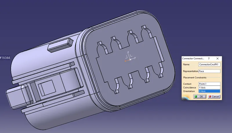
Next is defining connector connecting point. For this we call the command "Define connector connecting point" When this command is selected the window appears as seen below. The name can be selected as per company or individual requirement in our case we retain the default name. Then it asks for representation and in our case we select the front face of the connector. Then it asks for contact reference and we select the point created on the face at the centre. Then it asks for coincidence, we select Y axis which is projecting out as coincedence reference and then finally orientation is our x axis. After selecting all this we press OK and the connector connecting point is designated in this part. Next is defining bundle entry point.
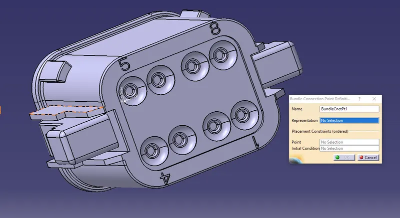
Next we select the command "Define Bundle Connection Point". Once this command is selected, it asks for the electrical component and we select the connector. A new window opens. First it asks for the name, I continue with the same name as the TE product then it asks for represantation which I select the outer face. Then it asks for point of bundle entry, I select the created point. Finally it asks for initial condition, again I select the same face which I selected for representation. This completes the selection of points and faces and I enter OK which creates bundle entry point for calling in assembly.
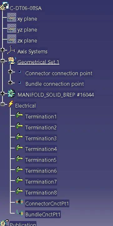
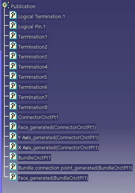
With this connector defining process is complete and below is the tree structure which appears.
Now we go for the next part defining
TYCO 174357-2. By pressing at the link given, it directs to the the web page of TE and to the detail specification of the connector.
This is a housing of Female terminals and is wire to wire connector.This can hold 3 female connectors and this product is by a company AMP. Like in the previous part we follow the same steps and down load the 3D zip file, extract the stp part and open it in catia, then save this as Catpart and then start defining the points and axis.
This is the picture of the web page of the connector housing. This is a 3 pin connector.
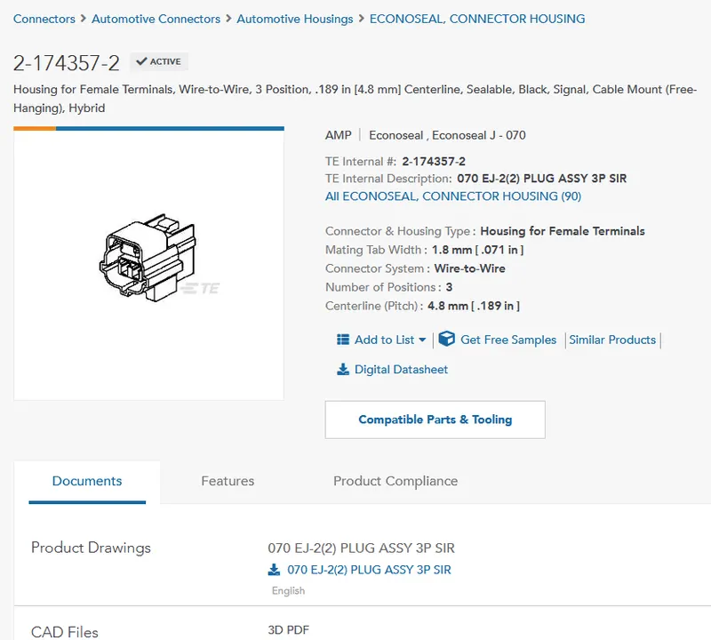
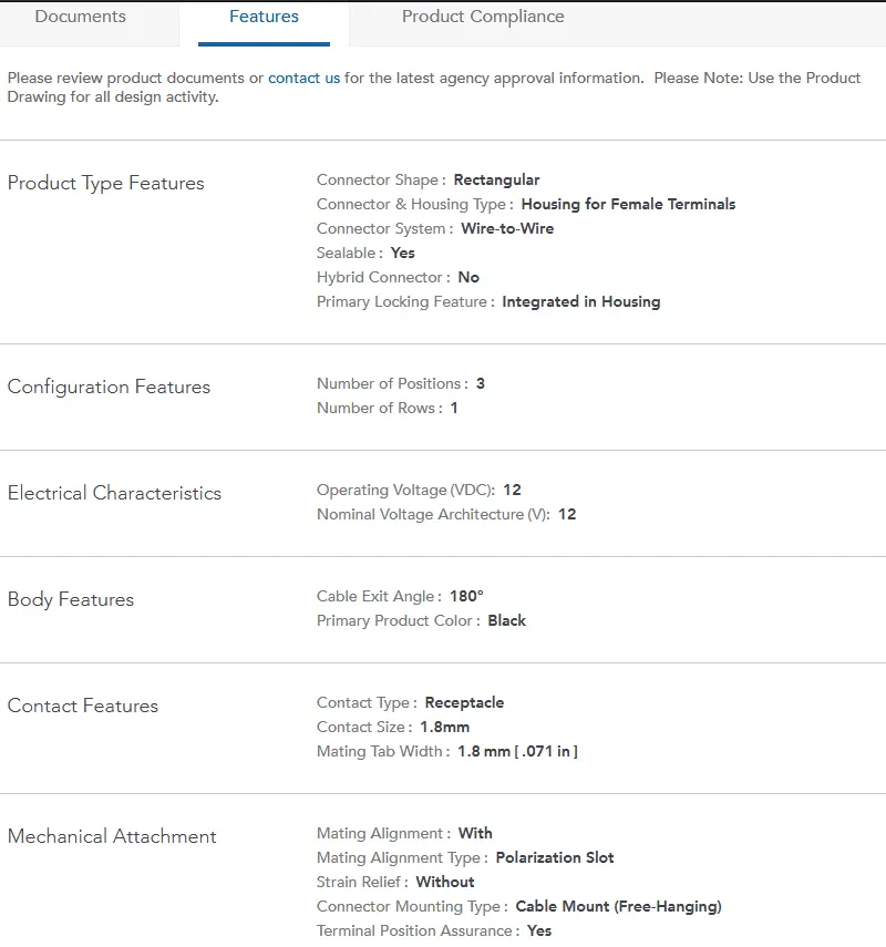
This connector is Receptacle
The down loaded 3D data of the connector looks as seen below.
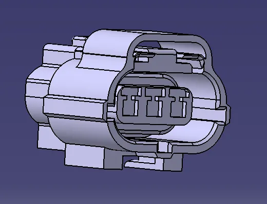
In Catia Part design we start defining the connector point with axis and bundle entry point. This also has a provision of mounting facility. So cavity mounting point also has to be defined so that it can be called in assembly to suit with mounting bracket or clamps.
The part is defined with centre point on the face of the connector as shown below and then an axis is positioned at that point with y axis projecting out x axis in horizantal direction and z axis in vertical direction. Once this point and axis is defined then bundle entry point is selected exactly at the centre of one of the connector wire entry hole, as shown below.
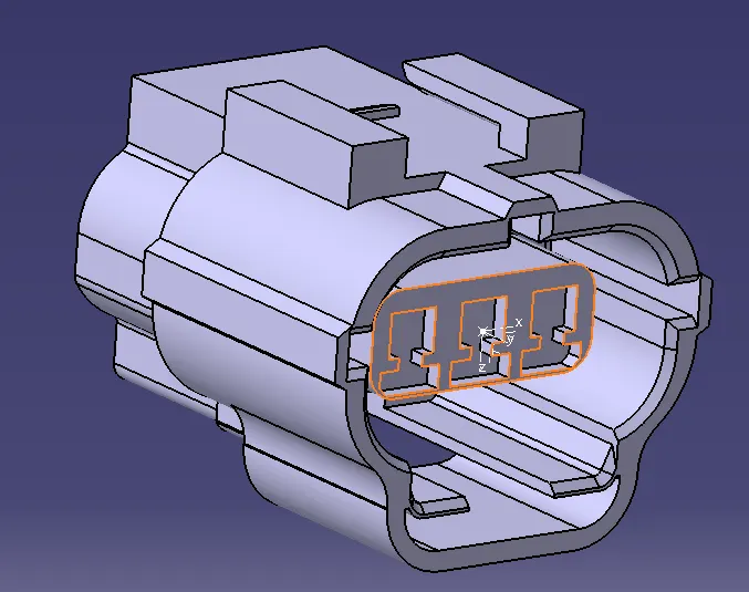
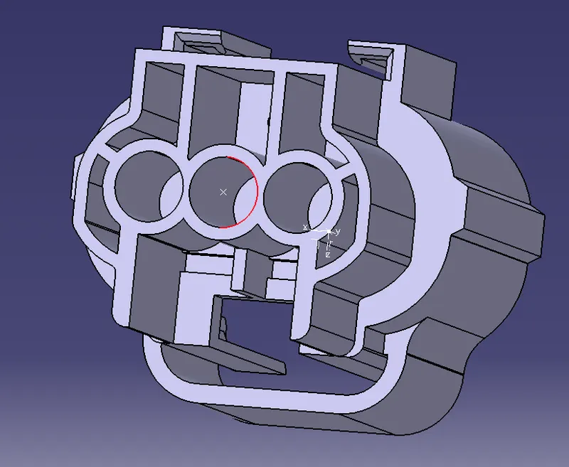
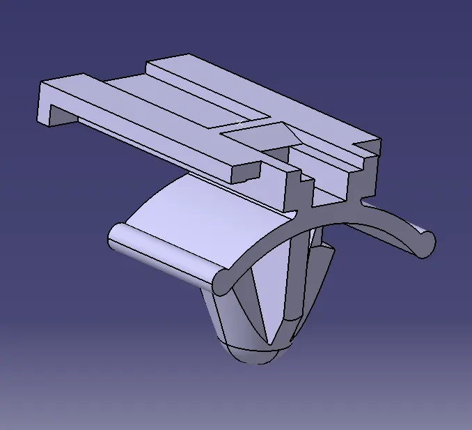
After fixing of connector connection point and bundle entry point than there is a provision of mounting the connector on a bracket. To define this cavity connect point is defined on the connector body after studying understainding the bracket which is going to fix on this connector, the oreintation and mating faces. See below the connector mounting bracket.
Now on the connector we define the cavity connecting point and the axis at this point for orientation of the mating bracket.
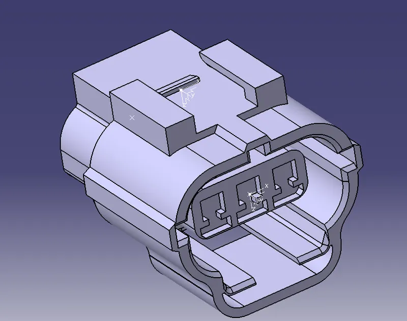
Now the connector is completly defined with all mating points. Next we save this as a electrical connector by changing to electrical part design in catia. We define this part as connector. In the window the part number is maintained same and number of termination is specified 3 as there only 3 wire inlets.
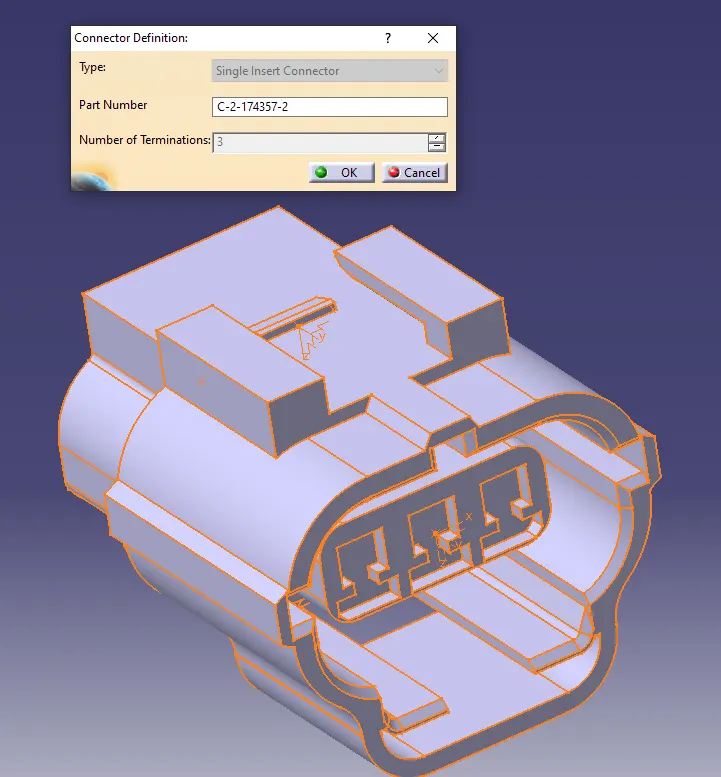
After defining this as a connector, we have to define connector connecting point. The name is retained same and the face is selected as the face where we have created the point. After selecting point the next is coincidence which is y axis and orientation is x axis and select ok which completes defining of connector connecting point. Next we define bundle entry point, which is opposite to the connector connecting point.
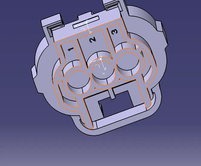
The part name is retained the same, the representation is the face of the connector and point is the same point created in the centre. Next the intial condition is same face selected earlier. This completes the bundle entry point defining.
Next the cavity connecting point defining.
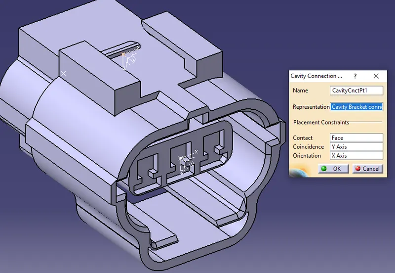
The name of the part is retained the default name. Representation is the point created on the middle of the edge, contact is the face where the point is created, coincidence is the Y axis and orientation is x axis. This completes the defining of all the mating points on this connector.
Next TYCO 85229-1
By pressing the link provided above we are directed to the web page of TE as seen below.
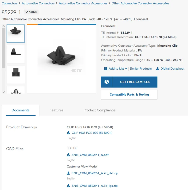
As the name says this is a connector accessories. This is a connecter mounting bracket. After down loading the CAD details a stp file available on the web page, this part is opened in catia and saved as catpart. The part looks as below.
In this we create mainly the bracket mating point with the connector, which is named here as cavity connecting point. First the assembly parameters are studied. The assembly between the connector and the bracket is studied, the mating faces, the orientation and the seating faces. Next cavity connecting point specified on the connector is studied and same orientation is specified on this of the three axis is defined here on this bracket as seen in the picture below.
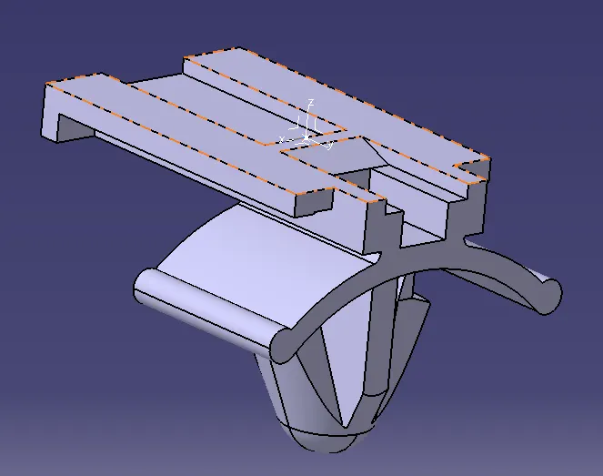
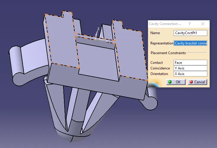
Only one point is required for assembly of this part. After defining the point, this part is defined electrically as mounting equipment. After defining this as a electrical part, this will be defined as cavity so the assembly in catia can recognise this as cavity and get assembled. After defining this as cavity the cavity connecting point is defined. In the window part name is retained default, representation is the point which was created and contact is the face the point lies, coincidence is the y axis and orientation is x axis. This completes defining of the part and mating points.
Next is defining catalogue and adding these parts into the catalogue.
Opened Catia selected new catalogue document file and created new catalogue file.
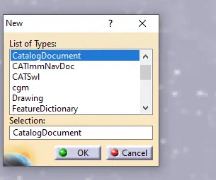
next the below window is opened and in the side commands we select Add family
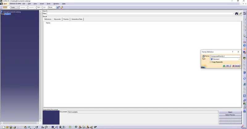
in the pop up window we select the name as "connector" and type as "electrical" and save the file as "connector" catalogue file. The file will be saved at the path selected.
Similarly I create one more catalogue file and name as "Mounting brackets & Clamps' and type as "electrical" and save the file as "Mounting bracket & clamps". This file is also saved at the path selected.
Next to add these catalogue files to catia environment, open catia and after opening catia we select tools-options-Equipments & systems-Electrical mapping
Window opens as seen below.
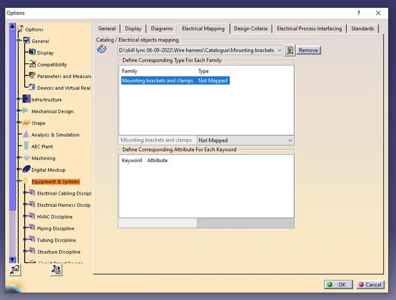
select add catalogue and select the catalogue file from the destination folder.
I add two catalogue files 1. Connector and 2. Mounting bracket and clamps.
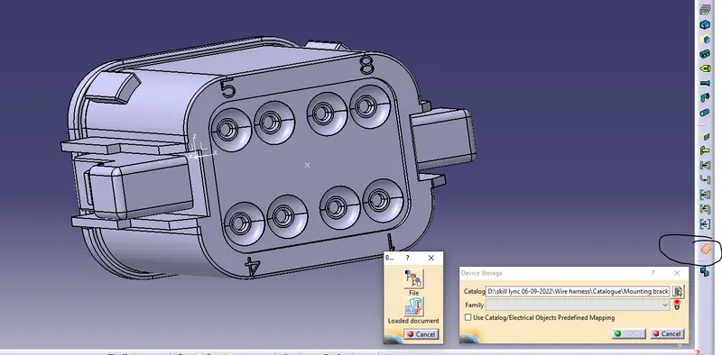
I open the defined electrical component connector DT06-O8SA and add this to the cataloge by selecting device storage command. When Device storage command is selected the window above appears and asks for the catalogue destination folder. I select the file from the destination and then it asks for the family. For connectors I have only option connectors and I select that and say ok. The connector gets stored in the catalogue file of connector. Similarly I do the same for the connector 174357-2. Even this part gets stored in connector catalogue library.
Next I open defined part 85229-1 and add to Device storage under mounting brackets and clamps catalogue.
This completes the challenge.